patent · US10505419B2
Wind power generator equipped with a cooling system
10 December 2019
Page 1 — bibliographic record
(12) United States Patent ( 10 ) Patent No.: US 10,505,419 B2 Pabst et al. (45 ) Date of Patent: * Dec . 10 , 2019 (54 ) WIND POWER GENERATOR EQUIPPED (52) U.S. CI.
WITH A COOLING SYSTEM CPC H02K 1/32 ( 2013.01); FO3D 80/60
(71) Applicant: Windfin B.V., Leimuiden (NL ) ( 2013.01) ; (Continued ) (72 ) Inventors: Otto Pabst, Rio Di Pusteria (IT ); (58 ) Field of Classification Search Georg Folie , Prato Allo Stelvio (IT ) ; CPC FO3B 2260/20 ; FO3D 80/60 ; HO2K 9/02 ; Matteo Casazza , Vipiteno (IT ); Paolo HO2K 9/04; HO2K 1/32 ; HO2K 7/1838 Bustreo , Vipiteno (IT ); Peter Gebhard , (Continued )
Velturno (IT) (56 ) References Cited (73 ) Assignee: WINDFIN B.V., Leimuiden (NL) U.S. PATENT DOCUMENTS ( * ) Notice: Subject to any disclaimer , the term of this 765,078 A * 7/1904 Jigouzo HO2K 16/00 patent is extended or adjusted under 35 310/112 U.S.C. 154(b ) by 455 days . 1,362,753 A 12/1920 Sperry This patent is subject to a terminal dis (Continued ) claimer .
FOREIGN PATENT DOCUMENTS
( 21) Appl. No .: 15 /091,354 DE 19636591 3/1998
OTHER PUBLICATIONS
India Office Action for Application No. 1455 /MUM / 2009 dated Oct.
US 2016/0218575 A1 Jul. 28 , 2016 6 , 2017
Primary Examiner - Julio C. Gonzalez
Related U.S. Application Data (74 ) Attorney, Agent, or Firm — Neal, Gerber & Eisenberg LLP (63 ) Continuation of application No. 13 /943,435 , filed on (57) ABSTRACT Jul. 16 , 2013 , now Pat. No. 9,312,741, which is a A wind power generator has a nacelle; a hub rotatable about (Continued ) an axis of rotation with respect to the nacelle ; at least two ( 30 ) Foreign Application Priority Data blades fitted to the hub ; an electric machine which is fitted to the nacelle , is bounded by an inner surface extending
Jun . 19 , 2008 (IT ) MI2008 A1122 about the axis of rotation , and has a rotor and a stator; and a cooling system for airflow cooling the electric machine , (51 ) Int. Cl. and which has a deflector body for defining a gap between FO3D 9/00 (2016.01) the deflector body and the electric machine and guiding the HO2K 132 (2006.01) airflow into the gap .
(Continued ) 14 Claims, 4 Drawing Sheets
22 224 28 A2
Page 2
Related U.S. Application Data 4,289,970 A 9/1981 Deibert
continuation of application No. 12 /485,645 , filed on 4,292,532 A 9/1981 Leroux Jun . 16 , 2009, now Pat. No. 8,492,919 . 4,336,649 A 6/1982 Glaser
(51) Int. Ci. 4,354,126 A 10/1982 Yates HO2K 1/27 (2006.01 ) 4,368,895 A 1/1983 Okamoto et al. HO2K 9/04 ( 2006.01 ) 4,398,773 A 8/1983 Boden et al. HO2K 7/18 4,452,046 A 6/1984 Valentin (2006.01) 4,482,831 A 11/1984 Notaras et al.
HO2K 9/02 ( 2006.01) 4,490,093 A 12/1984 Chertok et al . HO2K 5/18 ( 2006.01) 4,517,483 A 5/1985 Hucker et al . FO3D 80/60 ( 2016.01) 4,517,484 A 5/1985 Dacier FO3D 80/50 (2016.01) 4,521,026 A 6/1985 Eide
(52) U.S. CI. 4,613,779 A 9/1986 Meyer CPC HO2K 7/1838 (2013.01) ; HO2K 9/02 4,638,200 A 1/1987 Le Corre et al. (2013.01); HO2K 9/04 (2013.01); F03D 80/50 4,648,801 A
9/1987 Kawamura (2016.05 ); F05B 2220/7066 (2013.01); F05B 4,700,096 A 10/1987 Epars 2260/2241 ( 2013.01 ); H02K 2213/12 4,714,852 A 12/1987 Kawada et al . ( 2013.01); YO2E 10/725 (2013.01); YO2E 4,720,640 A 1/1988 Anderson et al.
(58 ) Field of Classification Search 4,724,348 A USPC 290/44 , 55 ; 415 / 4.1 , 4.2 , 4.3 , 4.5 ; 4,740,711 A * 4/1988 Sato FO1B 13/061 310/58, 59 , 60 R , 61, 60 A 290/52
See application file for complete search history . 4,792,712 A 12/1988 Stokes
(56 ) References Cited 4,866,321 A 9/1989 Blanchard et al.
1,894,357 A 1/1933 Manikowske et al. 4,976,587 A 12/1990 Johnston et al. 1,948,854 A 2/1934 Heath 5,004,944 A 4/1991 Fisher 1,979,813 A 11/1934 Reis 5,063,318 A 11/1991 Anderson 2,006,172 A 6/1935 Kla auf 5,090,711 A 2/1992 Becker 2,040,218 A 5/1936 Soderberg 5,091,668 A 2/1992 Cuenot et al . 2,177,801 A 10/1939 Erren 5,177,388 A 1/1993 Hotta et al. 2,469,734 A 5/1949 Ledwith 5,191,255 A 3/1993 Kloosterhouse et al. 2,496,897 A 2/1950 Strickland 5,275,139 A 1/1994 Rosenquist 2,655,611 A 10/1953 Sherman 5,280,209 A 1/1994 Leupold et al. 2,739,253 A 3/1956 Plumb 5,281,094 A 1/1994 McCarty et al. 2,806,160 A 9/1957 Brainard 5,298,827 A 3/1994 Sugiyama 2,842,214 A 7/1958 Prewitt 5,302,876 A 4/1994 Iwamatsu et al . 2,903,610 A 9/1959 Bessiere 5,311,092 A 5/1994 Fisher 3,004,782 A 10/1961 Meermans 5,315,159 A 5/1994 Gribnau 3,072,813 A 1/1963 Reijnst et al . 5,410,997 A 5/1995 Rosenquist 3,083,311 A 3/1963 Krasnow 5,419,683 A 5/1995 Peace 3,131,942 A 5/1964 Ertaud 5,456,579 A 10/1995 Olson 3,168,686 A 2/1965 King et al. 5,483,116 A 1/1996 Kusase et al. 3,221,195 A 11/1965 Hoffmann 5,506,453 A 4/1996 McCombs 3,250,926 A 5/1966 O'Reilly 5,579,800 A 12/1996 Walker 3,363,910 A 1/1968 Toronchuk 5,609,184 A 3/1997 Apel et al. 3,364,523 A 1/1968 Schippers 5,663,600 A 9/1997 Baek et al . 3,392,910 A 7/1968 Tanzberger 5,670,838 A 9/1997 Everton 3,468,548 A 9/1969 Webb 5,696,419 A 12/1997 Rakestraw et al . 3,643,119 A 2/1972 Lukens 5,704,567 A 1/1998 Maglieri 3,700,247 A 10/1972 Butler et al . 5,746,576 A 5/1998 Bayly 3,724,861 A 4/1973 Lesiecki 5,777,952 A 7/1998 Nishimura et al . 3,735,174 A * 5/1973 Bosch HO2K 3/00 5,783,894 A 7/1998 Wither
3,746,349 A 7/1973 Smale et al. 5,798,632 A 8/1998 Muljadi 3,748,089 A 7/1973 Boyer et al . 5,801,470 A 9/1998 Johnson et al. 3,749,953 A * 7/1973 Baumann HO2K 9/06 5,811,908 A 9/1998 Iwata et al.
3,751,699 A * 8/1973 Gleichman F16C 33/6651 5,844,341 A 12/1998 Spooner et al.
3,789,252 A 1/1974 Abegg 5,886,441 A 3/1999 Uchida et al. 3,841,643 A 10/1974 McLean 5,889,346 A 3/1999 Uchida et al. 3,860,843 A 1/1975 Kawasaki et al. 5,894,183 A 4/1999 Borchert 3,942,026 A 3/1976 Carter 5,925,964 A 7/1999 Kusase et al. 3,963,247 A 6/1976 Nommensen 5,952,755 A 9/1999 Lubas 3,968,969 A 7/1976 Mayer et al. 5,961,124 A 10/1999 Muller 4,022,479 A 5/1977 Orlowski 5,973,435 A 10/1999 Irie et al. 4,061,926 A 12/1977 Peed 5,986,374 A 11/1999 Kawakami 4,087,698 A 5/1978 Myers 5,986,378 A 11/1999 Caamaño 4,273,343 A 6/1981 Visser 6,013,968 A 1/2000 Lechner et al.
Page 3
( 56 ) References Cited 7,008,172 B2 3/2006 Selsam
6,037,692 A 3/2000 Miekka et al. 7,028,386 B2 4/2006 Kato et al. 6,064,123 A 5/2000 Gislason 7,038,343 B2 5/2006 Agnes et al. 6,089,536 A 7/2000 Watanabe et al . 7,042,109 B2 5/2006 Gabrys 6,093,984 A 7/2000 Shiga et al. 7,075,192 B2 7/2006 Bywaters et al. 6,127,739 A 10/2000 Appa 7,081,696 B2 7/2006 Ritchey 6,172,429 B1 1/2001 Russell 7,088,024 B2 8/2006 Agnes et al. 6,177,746 B1 1/2001 Tupper et al. 7,091,642 B2 8/2006 Agnes et al. 6,193,211 B1 2/2001 Watanabe et al . 7,095,128 B2 8/2006 Canini et al. 6,194,799 B1 2/2001 Miekka et al. 7,098,552 B2 8/2006 McCoin 6,215,199 B1 4/2001 Lysenko et al. 7,109,600 B1 9/2006 Bywaters et al. 6,215,212 B1 * 4/2001 Grennan HO2K 1/32 7,116,006 B2 10/2006 McCoin
6,232,673 B1 5/2001 Schoo et al . 7,154,191 B2 12/2006 Jansen et al. 6,246,126 B1 6/2001 Van Der Veken et al . 7,161,260 B2 1/2007 Krügen -Gotzmann et al. 6,278,197 B1 8/2001 Appa 7,166,942 B2 1/2007 Yokota 6,285,090 B1 9/2001 Brutsaert et al. 7,168,248 B2 1/2007 Sakamoto et al. 6,326,711 B1 12/2001 Yamaguchi et al. 7,179,056 B2 2/2007 Sieffriedsen 6,365,994 B1 4/2002 Watanabe et al. 7,180,204 B2 2/2007 Grant et al. 6,373,160 B1 4/2002 Schrödl 7,183,665 B2 2/2007 Bywaters et al. 6,376,956 B1 4/2002 Hosoya 7,196,446 B2 3/2007 Hans 6,378,839 B2 4/2002 Watanabe et al. 7,259,472 B2 8/2007 Miyake et al. 6,384,504 B1 5/2002 Elrhart et al. 7,281,501 B2 10/2007 Leufen et al. 6,417,578 B1 7/2002 Chapman et al. 7,285,890 B2 10/2007 Jones et al . 6,428,011 B1 8/2002 Oskouei 7,323,792 B2 1/2008 Sohn 6,452,287 B1 9/2002 Looker 7,358,637 B2 4/2008 Tapper 6,452,301 B1 9/2002 Van Dine et al . 7,377,163 B2 5/2008 Miyagawa 6,455,976 B1 9/2002 Nakano 7,392,988 B2 7/2008 Moldt et al. 6,472,784 B2 10/2002 Miekka et al . 7,427,814 B2 9/2008 Bagepalli et al. 6,474,653 B1 11/2002 Hintenlang et al. 7,431,567 B1 10/2008 Bevington et al. 6,476,513 B1 11/2002 Gueorguiev 7,458,261 B2 12/2008 Miyagawa 6,492,743 B1 12/2002 Appa 7,482,720 B2 1/2009 Gordon et al. 6,492,754 B1 12/2002 Weiglhofer et al. 7,548,008 B2 6/2009 Jansen et al. 6,504,260 B1 1/2003 Debleser 7,687,932 B2 3/2010 Casazza et al. 6,515,390 B1 2/2003 Lopatinsky et al. 8,053,918 B2 11/2011 Wobben 6,548,932 B1 4/2003 Weiglhofer et al. 9,312,741 B2 * 4/2016 Pabst HO2K 1/278 6,590,312 B1 7/2003 Seguchi et al. 2001/0035651 A1 11/2001 Umemoto et al. 6,603,232 B2 8/2003 Van Dine et al. 2002/0047418 Al 4/2002 Seguchi et al. 6,617,747 B1 9/2003 Petersen 2002/0047425 A1 4/2002 Coupart et al. 6,629,358 B2 10/2003 Setiabudi et al. 2002/0056822 Al 5/2002 Watanabe et al. 6,664,692 B1 12/2003 Kristoffersen 2002/0063485 Al 5/2002 Lee et al. 6,683,397 B2 1/2004 Gauthier et al. 2002/0089251 A1 7/2002 Tajima et al. 6,700,260 B2 3/2004 Hsu et al. 2002/0148453 A1 10/2002 Watanabe et al. 6,700,288 B2 3/2004 Smith 2003/0011266 A1 1/2003 Morita et al . 6,707,224 B1 3/2004 Petersen 2003/0102677 A1 6/2003 Becker et al. 6,720,688 B1 4/2004 Schiller 2003/0137149 A1 7/2003 Northrup et al. 6,727,624 B2 4/2004 Morita et al . 2003/0230899 Al 12/2003 Martinez 6,746,217 B2 6/2004 Kim et al. 2004/0086373 Al 5/2004 Page , Jr. 6,759,758 B2 7/2004 Martinez 2004/0094965 A1 5/2004 Kirkegaard et al. 6,762,525 B1 7/2004 Maslov et al. 2004/0119292 Al 6/2004 Datta et al. 6,781,276 B1 8/2004 Stiesdal et al . 2004/0150283 A1 8/2004 Calfo et al. 6,784,564 B1 8/2004 Wobben 2004/0151575 Al 8/2004 Pierce et al. 6,794,781 B2 9/2004 Razzell et al. 2004/0151577 A1 8/2004 Pierce et al. 6,828,710 B1 12/2004 Gabrys 2004/0179934 Al 9/2004 Wobben 6,856,042 B1 2/2005 Kubota 2004/0189136 Al 9/2004 Kolomeitsev et al. 6,879,075 B2 4/2005 Calfo et al. 2005/0002783 A1 1/2005 Hiel et al. 6,888,262 B2 5/2005 Blakemore 2005/0082839 Al 4/2005 McCoin 6,891,299 B2 5/2005 Coupart et al. 2005/0230979 Al 10/2005 Bywaters et al. 6,903,466 B1 6/2005 Mercier et al . 2005/0280264 A1 12/2005 Nagy 6,903,475 B2 6/2005 Ortt et al. 2006/0000269 Al 1/2006 LeMieux et al. 6,906,444 B2 6/2005 Hattori et al . 2006/0001269 A1 1/2006 Jansen et al . 6,911,741 B2 6/2005 Petteersen et al. 2006/0006658 Al 1/2006 McCoin 6,921,243 B2 7/2005 Canini et al. 2006/0012182 A1 1/2006 McCoin 6,931,834 B2 8/2005 Jones 2006/0028025 A1 2/2006 Kikuchi et al . 6,933,645 B1 8/2005 Watson 2006/0066110 A1 3/2006 Jansen et al. 6,933,646 B2 8/2005 Kinoshita 2006/0071575 Al 4/2006 Jansen et al. 6,942,454 B2 9/2005 Ohlmann 2006/0091735 A1 5/2006 Song et al. 6,945,747 B1 9/2005 Miller 2006/0125243 Al 6/2006 Miller 6,949,860 B2 9/2005 Hama et al . 2006/0131985 Al 6/2006 Qu et al. 6,951,443 B1 10/2005 Blakemore 2006/0152012 A1 7/2006 Wiegel et al. 6,972,498 B2 12/2005 Jamieson et al. 2006/0152015 A1 7/2006 Bywaters et al. 6,983,529 B2 1/2006 Ortt et al. 2006/0152016 A1 7/2006 Bywaters et al. 6,984,908 B2 1/2006 Rinholm et al . 2007/0012026 A1 * 1/2007 Dev F02C 3/045 6,987,342 B2 1/2006 Hans 60 /226.1 6,998,729 B1 2/2006 Wobben 2007/0024132 A1 2/2007 Salamah et al . 7,004,724 B2 2/2006 Pierce et al. 2007/0187954 A1 8/2007 Struve et al.
Page 4
Drawing sheet — no readable text.
Page 5
Drawing sheet — no readable text.
Page 6
Drawing sheet — no readable text.
Page 7
Drawing sheet — no readable text.
Page 8
Drawing sheet — no readable text.
Page 9
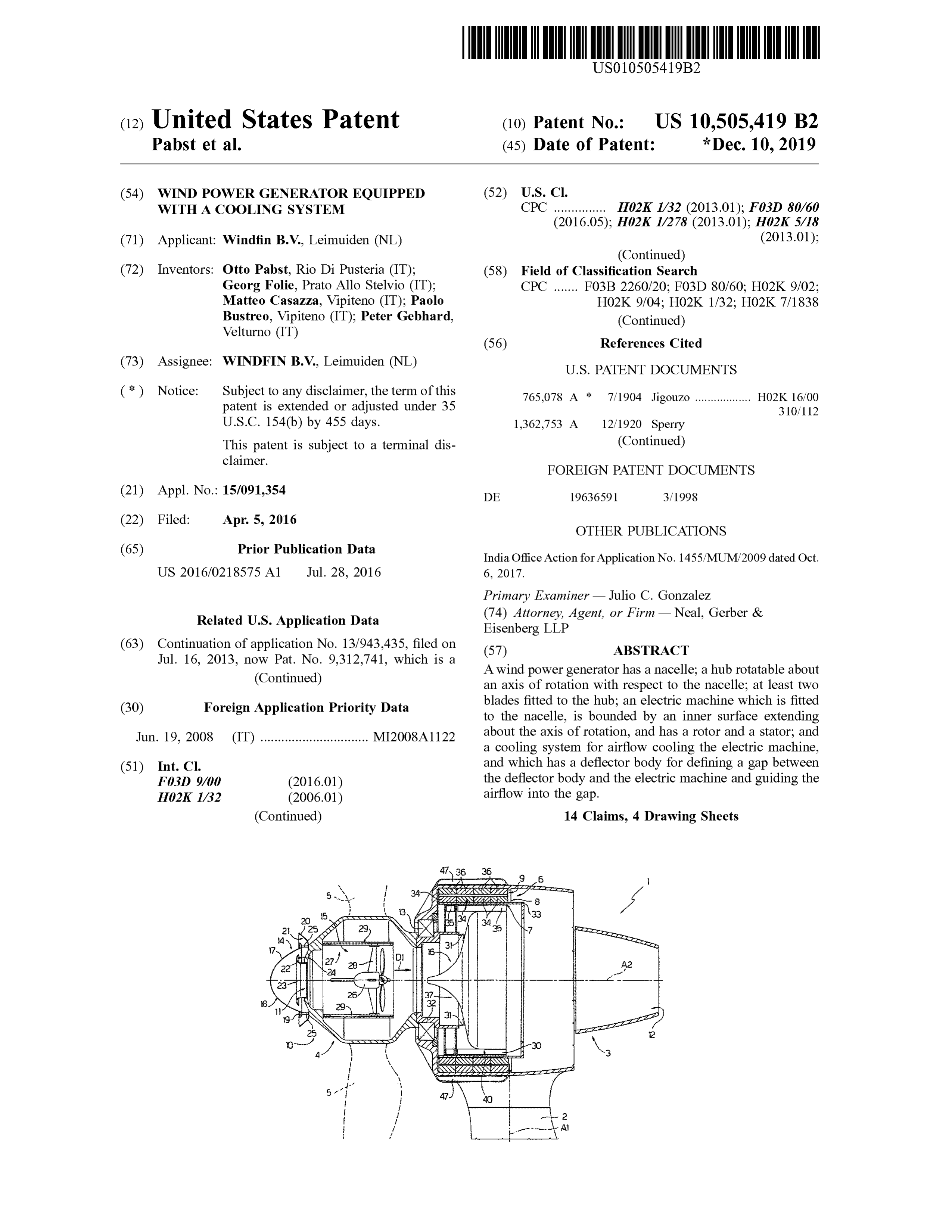
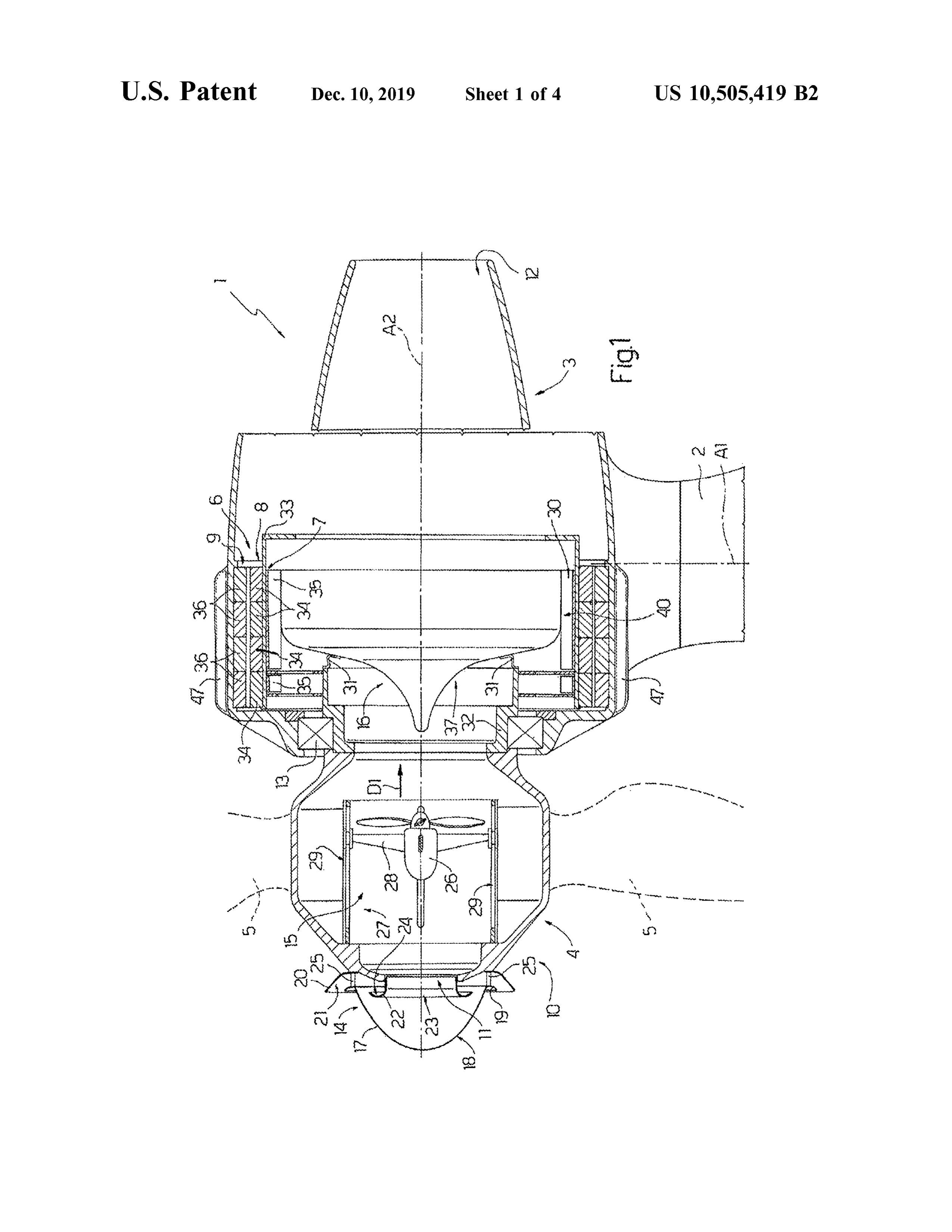
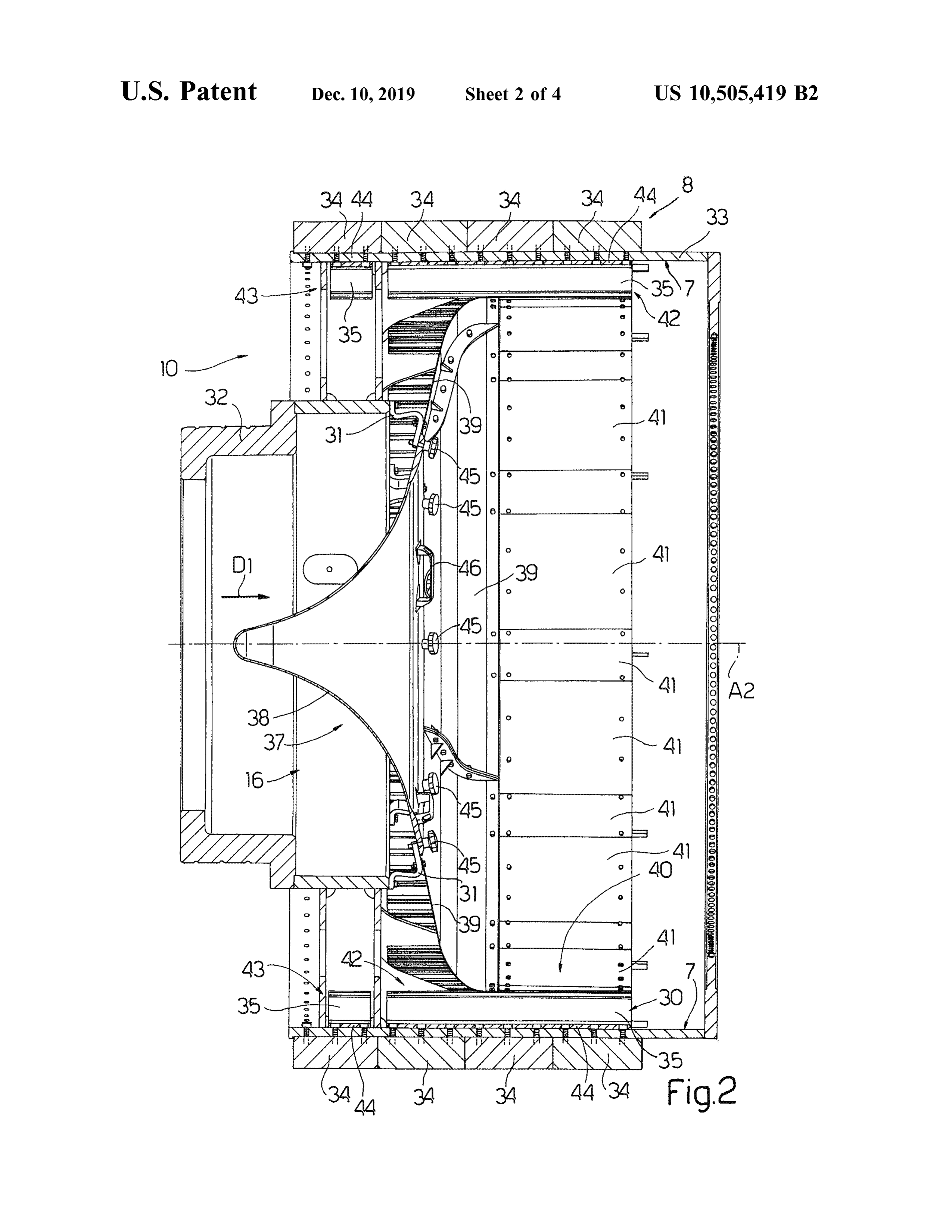
WIND POWER GENERATOR EQUIPPED FIG . 2 shows a larger- scale lateral section of a detail of WITH A COOLING SYSTEM the FIG . 1 wind power generator;
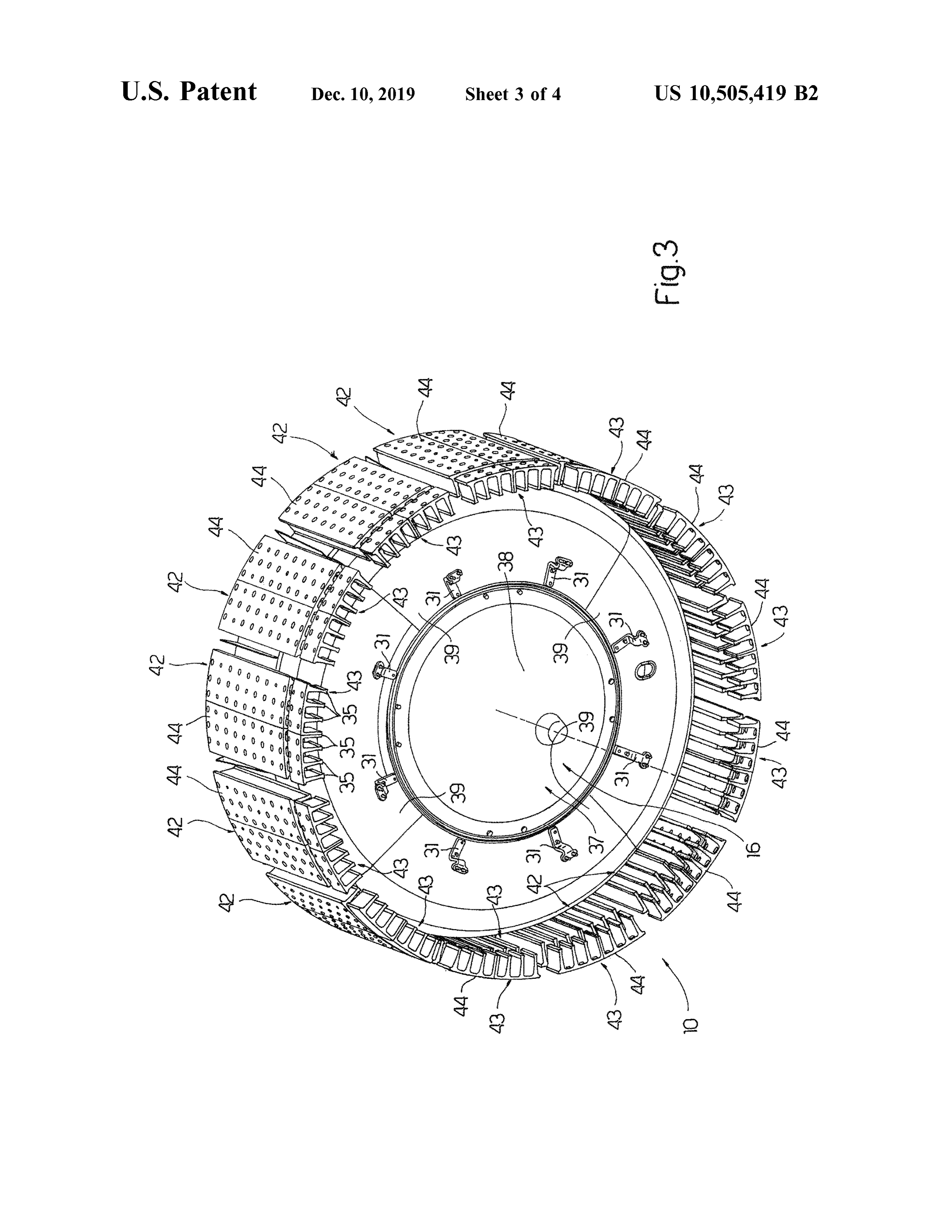
FIG . 3 shows a larger-scale view in perspective, with parts
PRIORITY CLAIM removed for clarity , of a detail of the FIG . 1 wind power 5 generator;
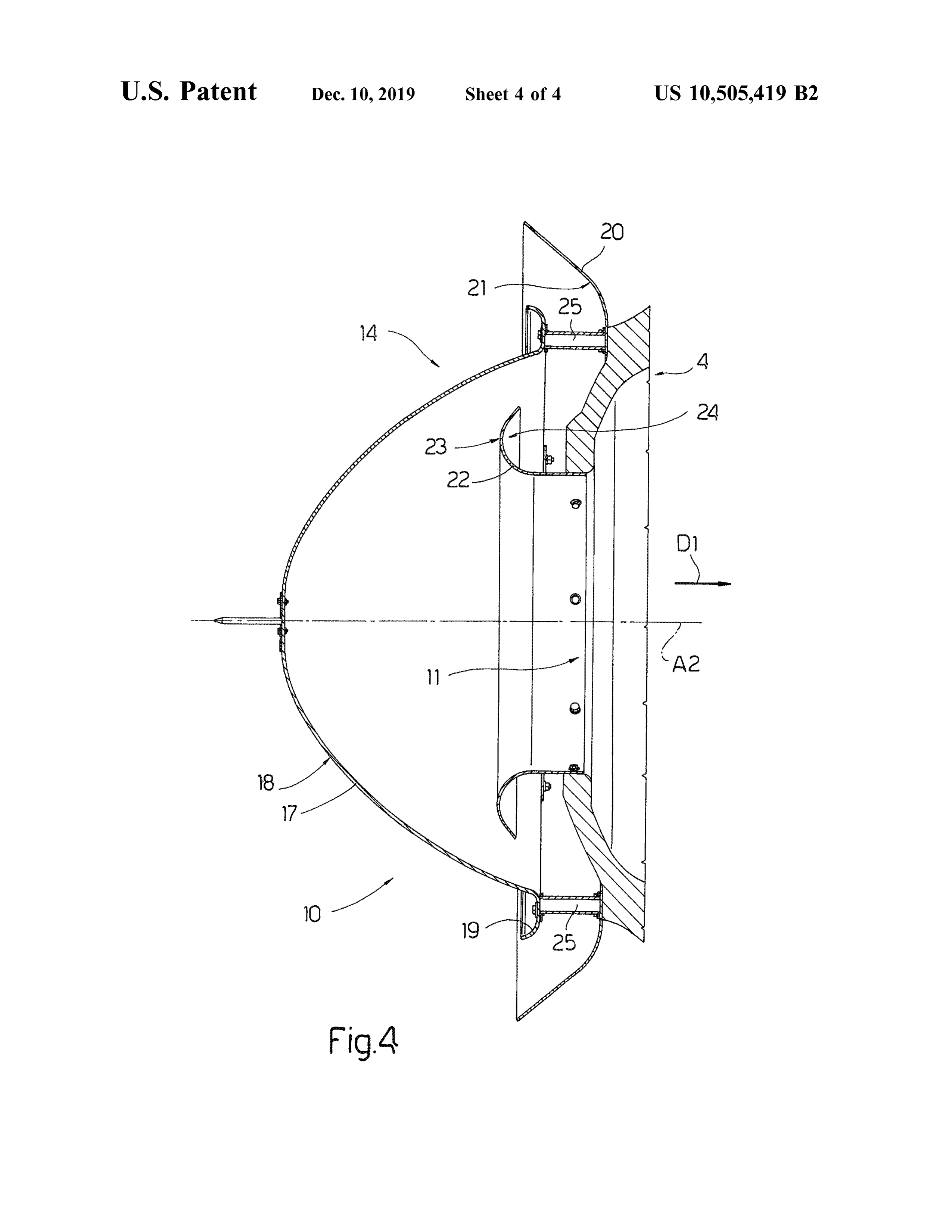
This application is a continuation of, claimsthe benefit of FIG . 4 shows a larger-scale lateral section of a detail of and priority to U.S. patent application Ser. No. 13 /943,435 , the FIG . 1 wind power generator.
filed on Jul. 16 , 2013 , which is a continuation of, claims the benefit of and priority to U.S. patent application Ser. No. DETAILED DESCRIPTION
8,492,919, which claims the benefit of and priority to Italian Number 1 in FIG . 1 indicates as a whole a wind power Patent Application No. MI2008A 001122 , filed on Jun . 19 , generator, which comprises a pylon 2 extending along a 2008, the entire contents of which are each incorporated by vertical axis Al; a nacelle 3 fitted to the top end of pylon 2 reference herein .
15 and rotatable with respect to pylon 2 about axis Al; a hub 4
BACKGROUND mounted to rotate with respect to nacelle 3 about an axis of rotation A2 crosswise to axis Al; and three blades 5, only
Known airflow cooling systems are not particularly effi twoPylon of which are shown by dash lines in FIG . 1. 2 is substantially defined by a hollow cylinder cient, especially in the case of generators equipped with a 20 housing stairs (not shown in the drawings ) and /or lifts (not cylindrical electric machine . shown in the drawings ).
SUMMARY Pylon 2 is normally secured to the ground by a foundation (not shown in the drawings ). Alternatively , in off - shore
The present invention relates to a wind power generator systems, pylon 2 is secured to a floating platform (not shown equipped with a cooling system . 25 in the drawings ).
More specifically , the present invention relates to a wind Nacelle 3 comprises a hollow body fitted to the top end of power generator comprising a nacelle ; a hub rotatable about pylon 2 to rotate about axis A1, and supports an electric an axis of rotation with respect to the nacelle; at least two machine 6 having a rotor 8 and a stator 9 , and bounded by blades fitted to the hub ; an electric machine which is fitted an inner surface 7 extending about axis of rotation A2 . In to the nacelle, is bounded by an inner surface extending 30 other words, electric machine 6 is a hollow cylindrical about the axis of rotation , and has a rotor and a stator ; and generator.
a cooling system for airflow cooling the electric machine. Likewise, hub 4 comprises a hollow body integral with It is an object of the present invention to provide a wind rotor 8 .
power generator equipped with a highly efficient cooling Wind power generator 1 comprises a cooling system 10 system . 35 supported partly by hub 4 and partly by nacelle 3, and which A further object of the present invention is to provide a serves to airflow cool electric machine 6 , and in particular to wind power generator equipped with a straightforward , conduct an airflow , predominantly in a direction D1 parallel low - cost cooling system . to axis of rotation A2 , from an inlet 11 in hub 4 to an outlet According to one embodiment of the present invention , 12 in nacelle 3 .
there is provided a wind power generator equipped with a 40 In the example shown in the drawings , stator 9 extends cooling system , the wind power generator comprising a about rotor 8 , and rotor 8 is integral with hub 4 and extends nacelle ; a hub rotatable about an axis of rotation with respect inside stator 9. The inner surface 7 of electric machine 6 is to the nacelle ; at least two blades fitted to the hub ; an electric therefore the inner surface of rotor 8 . machine which is fitted to the nacelle , is bounded by an inner Stator 9 is fixed or connected directly to nacelle 3 along surface extending about the axis of rotation , and has a rotor 45 an inner cylindrical surface of nacelle 3.Hub 4 and rotor 8 and a stator ; and a cooling system for airflow cooling the are connected to each other and supported by a bearing 13 electric machine, and which comprises a deflector body for in turn supported by nacelle 3 .
defining a gap between the deflector body and the electric In a variation not shown in the drawings, the rotor extends machine and guiding the airflow into the gap . about the stator, the stator is located inside the rotor, and the According to the present invention , the efficiency of the 50 inner surface of the electric machine is defined by the stator. cooling system is improved by the entire airflow being Cooling system 10 comprises, in succession from inlet 11 forced into the gap , which runs close to the electric machine to outlet 12 , an air intake filtration device 14 ; a ventilation and improves thermal exchange by preventing part of the unit 15 ; and a deflector body 16 .
airflow from flowing too far away from the hottest parts of With reference to FIG . 4 , filtration device 14 is fitted to the electric machine. 55 hub 4 , is located at inlet 11, and comprises a convex panel Additional features and advantages are described in , and 17 located in front of inlet 11 and having an outward - facing will be apparent from , the following Detailed Description convex face 18 and an oppositely -convex annular edge 19 ; and the figures. an annular panel 20 having a concave face 21 extending about edge 19 and facing convex panel 17 ; and an annular
BRIEF DESCRIPTION OF THE DRAWINGS 60 panel 22 extending inside convex panel 17 and comprising a convex face 23 facing convex panel 17, and a concave face
A non - limiting embodiment of the present invention will 24 facing hub 4 .
be described by way of example with reference to the Panel 17 is fitted to hub 4 by spacer arms 25 , whereas accompanying drawings, in which : panels 20 and 22 are fixed or connected directly to hub 4 FIG . 1 shows a partly sectioned side view , with parts 65 about inlet 11. Panels 17, 20 and 22 are guide panels for removed for clarity , of a wind power generator in accor guiding the air intake into hub 4 , and are designed and dance with the present invention ; positioned with respect to one another to define a labyrinth
Page 10
air intake path . Filtration device 14 thus prevents , or at least Airflow inside hub 4 and nacelle 3 is also assisted by fan reduces, entry of water, snow or impurities into hub 4 and 26 , which serves to overcome any load losses in the airflow , nacelle 3 . and increases airflow speed inside hub 4 and nacelle 3 . With reference to FIG . 1 , ventilation unit 15 is housed The airflow is diverted by deflector body 16 , and assumes inside hub 4 , and comprises a powered fan 26 ; a guide 27 5 first a predominantly radial and then a purely axial speed parallel to axis of rotation A2; and a slide 28 that runs along iscomponent , both with reference to axis of rotation A2. That , portion 37 serves to guide the airflow to inner surface 7 guide 27 in direction D1, and supports fan 26 .
Guide 27 comprises two rails 29 located about axis of of guide electric machine 6 , and portion 40 of deflector body 16 to and keep the airflow close to inner surface 7 of electric rotation A2 and extending in direction D1. Fan 26 serves to 10 machine 6 and fins 35 , so the entire airflow inside nacelle 3 increase airflow speed in direction D1 into nacelle 3 . contacts the hottest parts of electric machine 6 . Deflector body 16 serves to form a gap 30 between It should be understood that various changes and modi deflector body 16 itself and electric machine 6 , and to guide fications to the presently preferred embodiments described the airflow into gap 30 .
As shown more clearly in FIG . 2 , deflector body 16 is 15 changes and modificationsto can herein will be apparent those skilled in the art. Such be made without departing fixed or connected to electric machine 6 , in particular to from the spirit and scope of the present subject matter and rotor 8 , by means of brackets 31. without diminishing its intended advantages . It is therefore In the example shown in the drawings, and particularly in intended that such changes and modifications be covered by FIG . 1, rotor 8 comprises a sleeve 32 supported by bearing the appended claims.
13 and integral with hub 4 ; a cylindrical structure 33 integral 20 with sleeve 32 ; and permanent magnets 34 fixed along the The invention is claimed as follows: outer surface of cylindrical structure 33. Cylindrical struc 1. A hollow rotary electric machine cooling system com ture 33 defines inner surface 7, which is a cylindrical prising:
surface . a deflector wall including a tubular portion , wherein : Cooling system 10 also comprises fins 35 parallel to 25 (i) the deflector wall is housed in a hollow rotary direction D1 and fixed or connected to inner surface 7 of electrical machine defining a human passageway to cylindrical structure 33 . a hub of a wind power generator and including: Stator 9 comprises a stator pack 36 fixed or connected to ( a ) a stator , the surface of nacelle 3 ; and stator windings (not shown in 30 (b ) a shaftless hollow rotorwhich is distinct from the the drawings). tubular portion of the deflector wall, and With reference to FIG . 2 , deflector body 16 is substan ( c ) an inner tubular surface which extends about an tially axially symmetrical about axis of rotation A2, is fixed axis of rotation , or connected to sleeve 32 by brackets 31, and comprises a ( ii) the deflector wall is removeably connected to the substantially conical central portion 37 for guiding the shaftless hollow rotor of the hollow rotary electric
airflow to inner surface 7 and defined by a central panel 38 ( iii ) a cooling airflow guide gap is defined between the and by a number of panels 39 extending about central panel deflector wall and the inner tubular surface of the 38 ; and a cylindrical portion 40 facing and parallel to inner hollow rotary electric machine , said defined cooling surface 7, and which serves to define gap 30 and comprises airflow guide gap extending between the shaftless a number of panels 41. Panels 38 , 39 and 41 are connected 40 hollow rotor and the deflector wall. removably to one another. 2. The hollow rotary electric machine cooling system of With reference to FIG . 3 , fins 35 extend from inner claim 1, wherein the deflector wall includes a portion surface 7 of rotor 8 towards axis of rotation A2, and are configured to direct a cooling airflow to :
divided into groups 42 and 43, each of which , in addition to (i) the inner tubular surface of the hollow rotary electric a given number of fins 35 , comprises a perforated cylindrical 45 machine , and sector 44 fixed by screws to cylindrical structure 33. As ( ii ) the tubular portion of the deflector wall . shown in FIG . 3 , fins 35 and respective cylindrical sector 44 3. The hollow rotary electric machine of claim 1 , wherein are preferably formed in one piece. the deflector wall includes a plurality of panels assembled With reference to FIG . 2, panel 38 is fixed or connected adjacent to one another, at least one of said panels being to panels 39 by means of thumbscrews 45 , and comprises 50 configured to be removed .
grips 46 by which to remove panel 38 easily to allow access 4. The hollow rotary electric machine cooling system of by maintenance personnel inside hub 4 . claim 1, wherein the inner tubular surface of the hollow With reference to FIG . 1 , fan 26 is movable along axis of rotary electric machine is an inner tubular surface of the rotation A2 to allow passage by maintenance personnel and shaftless hollow rotor .
also to set the fan to the best operating position . 55 5. A hollow rotary electric machine comprising : Cooling system 10 also extends partly outside nacelle 3 , a stator;
and comprises fins 47 parallel to axis of rotation A2 and a shaftless hollow rotor housed within the stator and fixed or connected to the outer surface of nacelle 3 , at stator having an inner tubular surface which defines a human 9 , to assist cooling stator 9 . passageway to a hub of a wind power generator; and In actual use , nacelle 3 is oriented about axis A1 so that 60 a deflector wall at least partly housed in the shaftless axis of rotation A2 is positioned in the wind direction , with hollow rotor, said deflector wall including a tubular blades 5 into the wind , and the airflow therefore flows portion , wherein a cooling airflow guide gap is defined naturally along the labyrinth path into inlet 11 , through hub between the deflector wall and the inner tubular surface 4 and nacelle 3, and out through outlet 12. At the same time, of the shaftless hollow rotor, the deflector wall is part of the air flows over the outer surface of nacelle 3 and 65 removeably connected to the shaftless hollow rotor, and onto fins 47, which increase the air -stator 9 heat exchange the shaftless hollow rotor is distinct from the tubular surface . portion of the deflector wall.
Page 11
6. The hollow rotary electric machine of claim 5 , wherein assembled adjacent to one another, at least one of said panels the deflector wall includes a portion configured to guide an being configured to be removed .
airflow to : (i) the inner tubular surface of the shaftless 11. The hollow rotary electric machine cooling system of hollow rotor and (ii) the tubular portion of the deflector wall. claim 8 , wherein the inner tubular surface of the hollow 7. The hollow rotary electric machine of claim 5 , wherein 5 rotary electric machine is an inner tubular surface of the the deflector wall includes a plurality of panels assembled shaftless hollow rotor.
adjacent to one another, at least one of said panels being 12. A hollow rotary electric machine comprising: configured to be removed . a stator;
8. A hollow rotary electric machine cooling system com a shaftless hollow rotor housed within the stator and prising : 10 a deflector wall including a tubular portion , wherein : having an inner tubular surface defining a human (i) at least part of the deflector wall is removeably passageway to a hub of a wind power generator; housed in a hollow rotary electrical machine defining a deflector wall at least partly removeably housed in the a human passageway to a hub of a wind power shaftless hollow rotor, said deflector wall including a generator and including : 15 tubular portion , wherein a cooling airflow guide gap is ( a ) a stator, defined between the deflector wall and the inner tubular (b ) a shaftless hollow rotor which is distinct from the surface of the shaftless hollow rotor and the shaftless tubular portion of the deflector wall, and hollow rotor is distinct from the tubular portion of the ( c ) an inner tubular surface which extends about an deflector wall ; and axis of rotation , and 20 a plurality of cooling fins connected to the inner tubular (ii) a cooling airflow guide gap is defined between the surface of the shaftless hollow rotor. deflector wall and the inner tubular surface of the 13. The hollow rotary electric machine of claim 12 , hollow rotary electric machine ; and wherein the deflector wall includes a portion configured to a plurality of cooling fins connected to the hollow rotary guide an airflow to :
electric machine along the inner tubular surface . 25 (i)andthe inner tubular surface of the shaftless hollow rotor, 9. The hollow rotary electric machine cooling system of claim 8 , wherein the deflector wall includes a portion ( ii ) the tubular portion of the deflector wall. configured to direct a cooling airflow to :
14. The hollow rotary electric machine of claim 12 , (i) the inner tubular surface of the hollow rotary electric wherein machine, and 30 the deflector wall includes a plurality of panels (ii) the tubular portion of the deflector wall. assembled adjacent to one another, at least one of said panels 10. The hollow rotary electric machine of claim 8 , being configured to be removed .
wherein the deflector wall includes a plurality of panels
Provenance
- Collection
- Patents citing this work
- Original assignee
- Windfin BV
- Pages
- 11
- Method
- pdftotext (the PDF's own text layer) + pdftoppm 300dpi page scans
- Patent office record
- patents.google.com →
- Source
- Google Patents citing-documents table
- Inventors
- Otto Pabst; Georg Folie; Matteo Casazza; Paolo Bustreo; Peter Gebhard; Windfin BV
- Published
- 2019-12-10
- Transcribed from
- patentimages.storage.googleapis.com →