patent · US3700247
Flush cooling of shaft sealing screw means
24 October 1972
Page 1 — bibliographic record
United States Patent 15, 3,700,247 Butler et al. (45) Oct. 24, 1972 (54) FLUSH COOLING OF SHAFT SEALNG 3,246,901 4f1966 Wickli..................... 277/28 X SCREW MEANS 1,558,630 10/1925 Reed........................ 277/28 X
72) Inventors: Robert G. Butler, Dayton, Ohio;
Don E. Carter, Creve Coeur, Mo.; Prinary Examiner-Samuel B. Rothberg
George A. Latinen, deceased, late of Attorney-John W. Klooster et al.
Springfield, Mass. by May V.
Latinen, administratrix (57) ABSTRACT 73) Assignee: Monsanto Company, St. Louis, Mo. In certain shaft seals using a viscoseal-type sealing 22 Filed: Aug. 16, 1971 screw such as those adjacent the pressurized screw pump section of a viscous liquid devolatilizer, exces (21) Appl. No.: 172,106 sive heat buildup and/or prolonged elevated tempera ture exposure in the seal region can either deteriorate 52 U.S. Cl............... 277/28, 259/191,259/DIG. 16, the liquid materials in the sealing screw or render such 277/67,277/34 liquids less viscous to an extent such that the seal is no longer fully operative. To cool and flush the sealing 51 Int. Cl............................ F16j 15/40, F16j 15/54 screw and the liquid materials therein, a fluid conduit 58 Field of Search........ 277/64, 67, 134, 28, 58, 71, bringing fresh liquid material continuously to the seal 277/72; 259,191, DIG. 16 ing screw from the adjacent pressurized section is pro vided.
6 Claims, 7 Drawing Figures
UNITED STATES PATENTS
3,364,523 1 / 1968 Schippers.............. 277/134 X
PRODUCT
OUT
Ses
Page 2
Drawing sheet — no readable text.
Page 3
PATENTEDOCT24 1972 3.7OO,247
F.G. 2 83 E s2
EEE
EiS
Trs
SID ALLIS
ReneRam
earanarawer recoraleexsee
PRODUCT S
OUT ar?é%
SyyySYS
DON E. CARTER,
GEORGE E LAT NEN
ATTORNEY
Page 4
Drawing sheet — no readable text.
Page 5
SHEET . Of 4
ROTATION
Oo 900 8 Oo 27Oo 36O
ROTATION -o-
APPROX MATE EFFECT VE
CHANNEL LENGTH
CONTROLLER
INVENTORS
ROBERT G. BUTLER,
DON E. CARTER,
GEORGE E LATIN EN
ATTORNEY
Page 6
FLUSH COOLNG OFSHAFTSEALNGSCREW cause the fluid in the seal to degrade and decompose, MEANS or it can cause the viscosity of the fluid to decrease to BACKGROUND the point where it is ineffective in producing sealing ac tion in the seal. The product fluid adjacent to the seal
ViscoSeal-type sealing screw assemblies are some may become contaminated with undesirable degrada times employed in such apparatus as extruders and tion products. Thus, conventional viscoseal-type seal wiped film devolatilizers to provide a seal for viscous ing screw assemblies are limited in usefulness and in ap fluids in the region between a rotating shaft and a hous plication.
ing wall adjacent a zone of relatively high viscous fluid O There has now been discovered a technique whereby pressure. A viscoseal-type sealing screw assembly can one can use a reverse screw viscoseal-type sealing be regarded as a single screw pump of the type which screw assembly in seals for viscous fluids which may be operates by making use of the viscosity of the fluid heat sensitive, thereby extending the usefulness of such being pumped. a sealing screw assembly. The technique involves the Thus, in a conventional viscoseal-type sealing screw 15 flushing and cooling of such an assembly by using the assembly, within a hub region defined in a housing ad viscous fluid itself. Thus, a stream of fresh viscous fluid, jacent a pressurized fluid filled zone where a revolving taken for example from an adjacent zone wherein such shaft extends axially therethrough, reverse screw fluid is pressurized, is continuously fed to the low pres threads are located. The threads are located either on sure end of a viscoseal-type sealing screw assembly and the hub or on the shaft. The threads extend circum is pumped by the seal itself back into the adjacent zone ferentially about the shaft and the hub. When the shaft of pressurized fluid at the high temperature, high pres rotates at a predetermined speed, and fluid from the sure end of the seal. The heat generated in the seal ap pressurized Zone is pushed against the threads, a seal is pears as increased sensible heat in the stream of fluid formed between the hub and the shaft by the fluid and circulated through the seal. The rate of fluid circulation the threads. 25 through the seal is chosen so that the rise in tempera Grooves between thread ribs fill with fluid and bridge ture of the fluid in the seal is small enough so that the a small gap between hub and shaft. Because the fluid in fluid will not be heated enough to degrade it or to im a groove has substantial viscosity, it tends to be dragged pair its sealing effectiveness (by reducing its viscosity). along by the revolving shaft in a circumferential The technique can be practiced automatically. direction. Such fluid movement, however, is stopped by 30 a screw thread whose land area acts as a barrier to such SUMMARY fluid flow. At such barrier, the force exerted on such The present invention is directed to a flush cooling fluid may be resolved into a component perpendicular to the walls of the groove formed by the thread and a assemblymeans for use with a viscoseal-type sealing screw where a shaft rotates in a pressurized fluid medi component parallel to the direction of the groove 35 um. The assembly formed by adjacent threads. Since the groove is open at ing having definedutilizes a fluid tight, elongated hous therein at adjacent adjoining re the end, the tendency of the latter force is to cause gions, generally along a common axis extending movement of the fluid along the groove. In a conven therethrough, certain chambers, including a cylindrical tional viscoseal-type sealing screw, the groove fills until sealing chamber and a pressurizable fluid chamber. the force parallel to the direction of the groove equals 40
Extending between the chambers is a rotatable shaft.
the pressure force at the end of the groove. Associated with the shaft is sealing screw means in the Such a conventional viscoseal-type sealing screw as sembly thus operating necessarily dissipates mechani sealing chamber. Such screw means has circum ferentially located, radially projecting, helically extend cal energy, and converts much of this mechanical ener ing rib portions adapted to urge fluid into said fluid gy into heat, because the fluid between the moving chamber 45 shaft and the stationary hub or housing is in viscous away from the sealing chamber, thereby to shear. This heat must necessarily be transferred from form between the shaft and the adjacent sealing the active length of the seal by some means. chamber walls a seal during shaft rotations with pres When the viscosity of a fluid is low, for example, surized fluid in the fluid chamber.
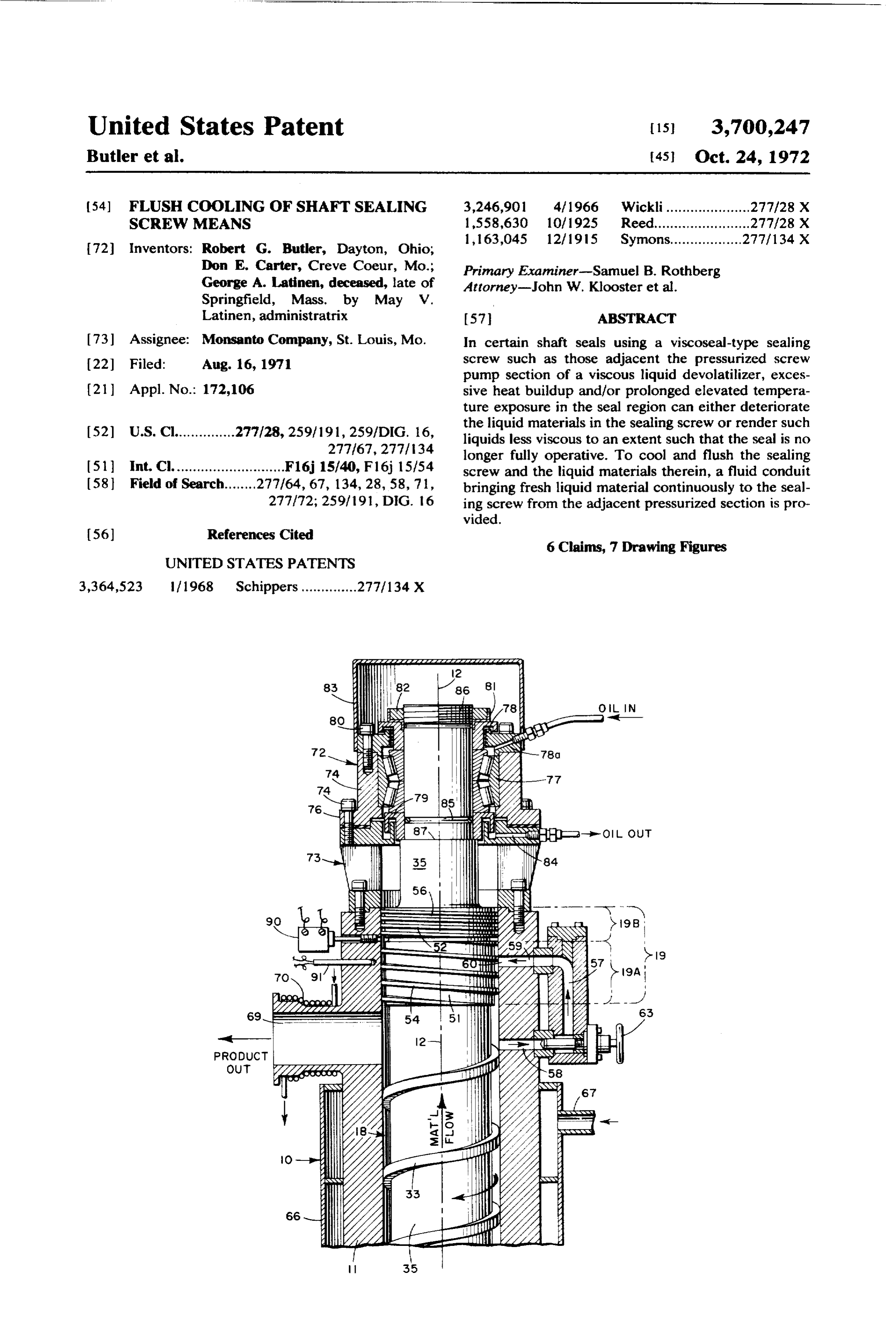
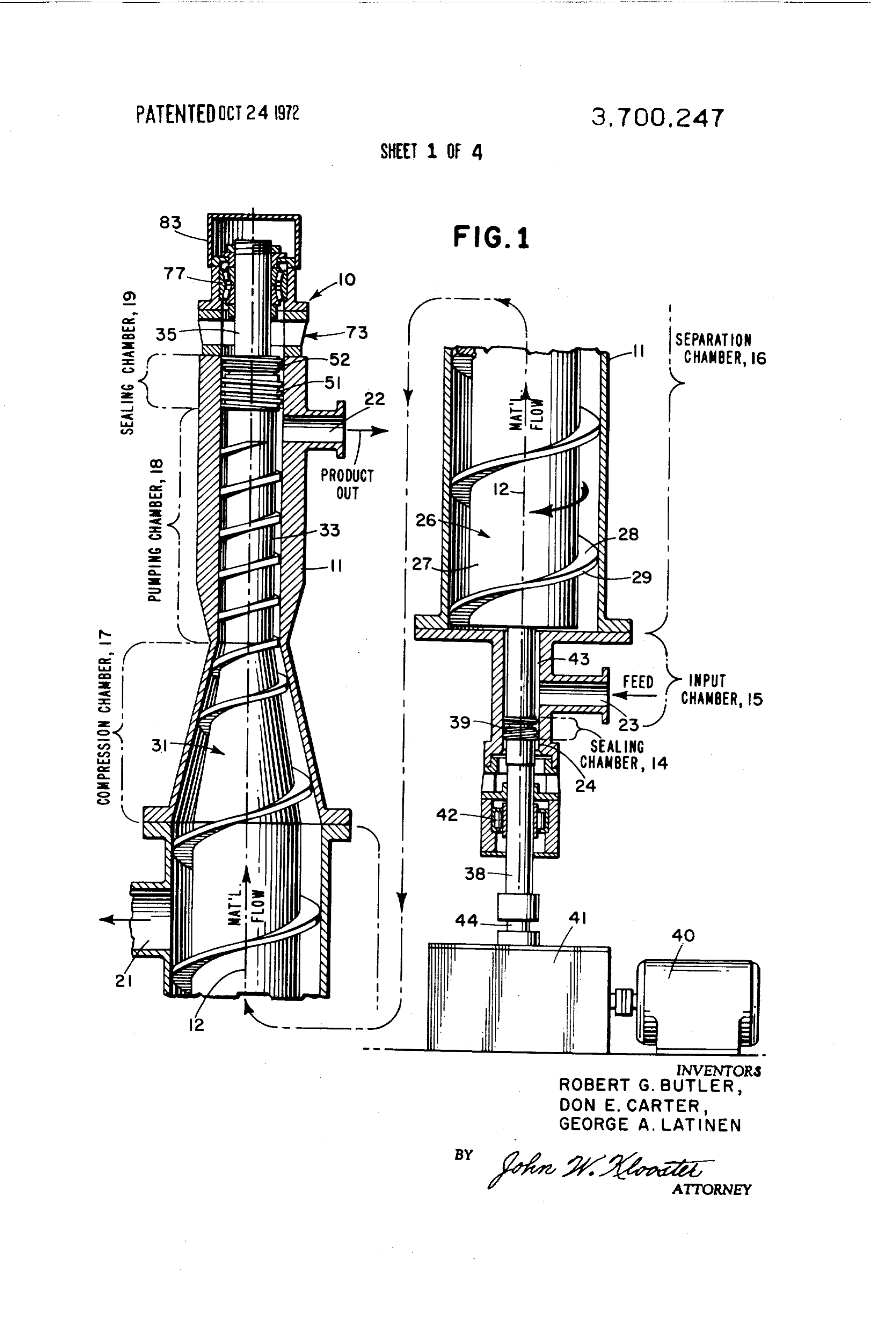
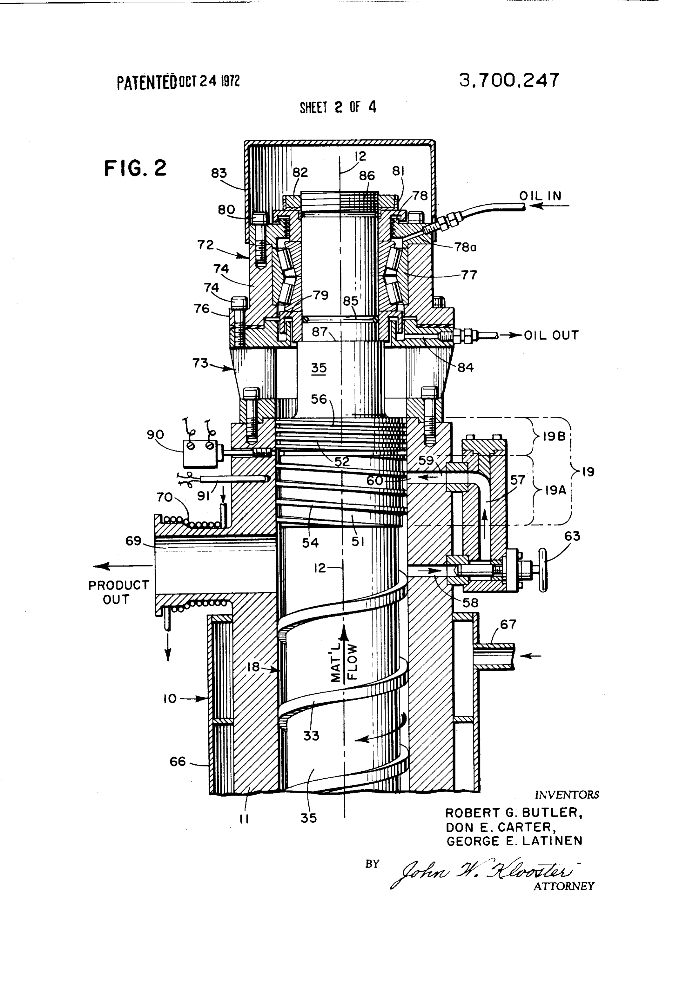
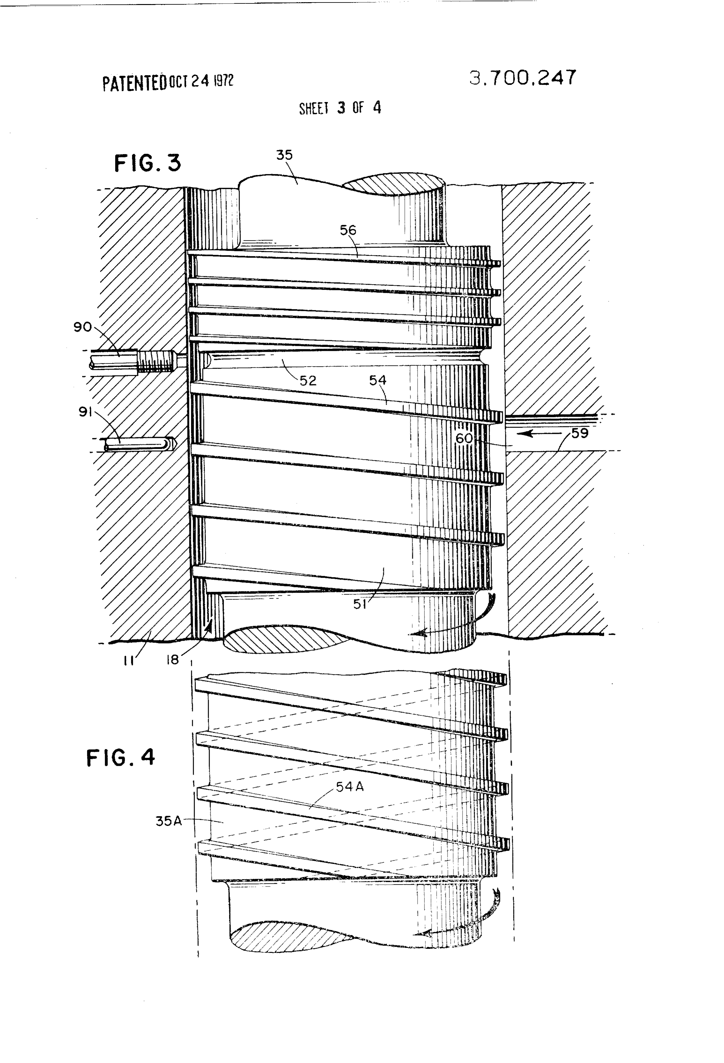
when the fluid is water, lubricating oil, gasoline, or the 50 Conduit means interconnects the fluid chamber with like, the active length of a viscoseal-type seal tends to the sealing chamber, and such pipe means is adapted to be long, and the generation of heat per unit length, convey fluid from the fluid chamber into the sealing small. In such a case, the heat may generally be chamber when the fluid chamber is pressurized with removed without excessive temperature buildup in the 55 fluid and the shaft rotates, fluid used for sealing through the use of such means as DRAWINGS a cooling fluid jacket on the housing (or barrel), radia tion, transfer of heat along the shaft and/or housing, or The present invention is better understood by the like. reference to the attached drawings wherein: However, when the viscosity of the fluid is high, for FIG. 1 is a diagrammatic representation of a wiped example, when the fluid is a melted polymer, or the 60 film devolatilizer suitable for utilizing therein a flush like, the active length of a viscoseal-type seal tends to cooling assembly of the present invention; be short, and the generation of heat per unit length FIG. 2 is an enlarged detailed vertical sectional view tends to be very high. In this case, it may not be possi of the output portion of a devolatilizer similar to that ble conveniently to remove heat from the active length shown in FIG. 1 but equipped with an embodiment of a rapidly enough by external cooling means to prevent 65 flush cooling assembly of this invention; excessively high temperatures from building up in the FIG. 3 is an enlarged vertical sectional view of the active length of the seal. Such temperature buildup can sealing screw arrangement shown in FIG. 2;
Page 7
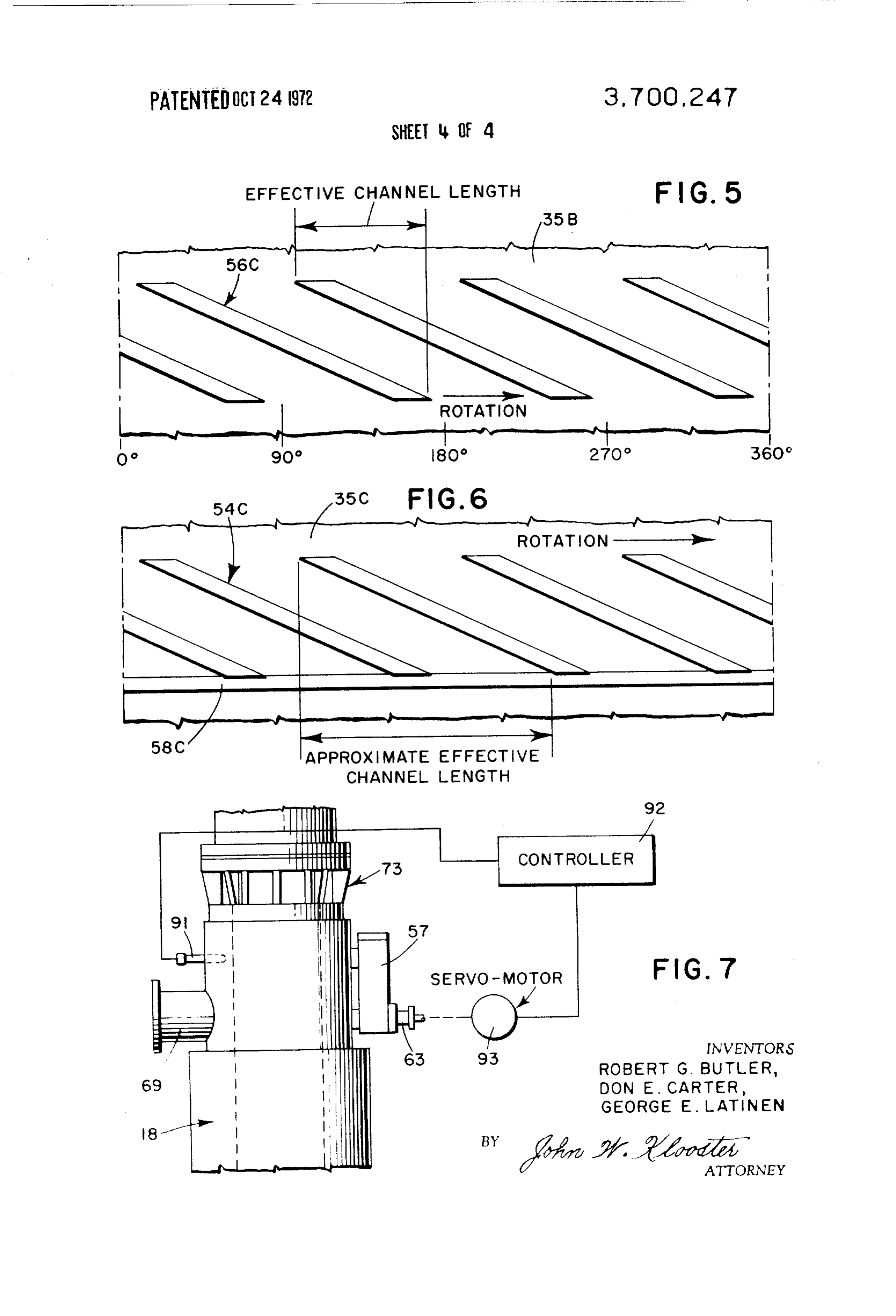
FIG. 4 shows an alternative embodiment of one of generally coaxial with, the pumping chamber 18. The the two viscoseal-type sealing screws employed in the extruder screw means 33 is adapted to compress, con embodiment of FIGS. 1-3; vey, and pressurize melt from the compression FIG. S shows an alternative arrangements of the chamber 17 to the melt output port 22.
other of the two viscoseal-type sealing screws arrange 5 A shaft 35 is positioned within, and generally coaxial ments shown in FIGS. 1-3; with, the second sealing chamber 19. Sealing means, FIG. 6 shows an embodiment similar to that of FIG. 5 here viscoSeal-type reverse screws 51, 52 on shaft 35, but with an integral circumferential end dam; and block passage of melt from pumping chamber 18 FIG. 7 is a schematic diagram of an automatic con therethrough alongshaft 35.
trol system for adjusting the flow of melt in the embodi O
A shaft 38 is positioned within, and generally coaxial ment of FIG. 2. with, both first melt sealing chamber 14 and melt input DETAILED DESCRIPTION chamber 15. A viscoseal-type reverse screw means 39 on shaft 38 is adapted to block passage of melt from
Turning to FIG. 1, there is seen a wiped film input chamber 15 therethrough along shaft 38 for pur devolatilizer, herein designated in its entirety by the nu 15 poses of the present invention. meral 10. The devolatilizer 10 has a housing 11 which Observe that each of reverse screws 51, 52 and has therewithin at successive adjoining regions along a reverse screw 39 have circumferentially located, radi common axis 12 extending therethrough various cham ally projecting, spirally extending rib portions arranged bers, as follows: a first or lower melt sealing chamber 20 So that, when melt under pressure is forced into the 14, a melt input chamber 15; an enlarged, elongated, grooves between such respective rib portions of such cylindrical vapor separation chamber 16; a melt transi screws, the melt is urged in an axial direction away tion or melt compression chamber 17; a melt pumping from the respective shaft ends and towards the pres chamber
18; and a second upper melt sealing chamber surizing fluid in, respectively, melt input chamber 15 25 and melt pumping chamber 18. Fluid or melt is forced
Housing 11 has defined therein various ports, as fol into tight engagement between housing 11 walls and lows: a vapor take-off port 21 in a separation chamber respective shafts 35 and 38 in the region of these 16; a melt output port 22 in the melt pumping chamber screws, thereby to produce the seals desired in each 18 adjacent the melt sealing chamber 19; a melt input respective sealing chamber 14 and 19 during operation port 23 in the input chamber 15; and a drive shaft entry 30 of devolatilizer 10.
port 24 into melt sealing chamber 14 located coaxially Shaft 38, in cooperation with housing 11 in the re on axis 12. Those skilled in the art will appreciate that, gion of input chamber 15, defines an annular space 43 alternatively, a drive shaft entry port (not shown) could between the shaft 38 and the housing 11 along an axi enter melt sealing chamber 19, as when a devolatilizer 35 ally extending distance from first sealing chamber 14 to is top driven. separation chamber 16. A roller bearing 42 supports A rotor assembly, herein designated in its entirety by the lower end of shaft 38.
the numeral 26, is positioned generally within, and Shaft 38 is integral with rotor assembly 26; rotor as generally coaxial with, the separation chamber 16. sembly 26 with compression screw means 31; compres Rotor assembly 26 has an elongated shaft means 27 axi 40 sion screw means 31 with extruder screw means 33; ally located in separation chamber 16 with screw ribs and extruder screw means 33 with shaft 35; thereby 28 extending radially outwardly therefrom and ter adapting shaft 38, rotor assembly 26, compression minating in land regions 29 at the circumferentially ex screw means 31, extruder screw means 33, and primary tending radial outer edges thereof, shaft portion 35 for common rotational movements on The land regions 29 are adapted to sweep by interior 45 a common axis.
walls of housing 11 in separation chamber 16 during Drive shaft 44 is coupled to shaft 38 and is driven by each revolution of shaft means 27. Rotor assembly 26 is motor-transmission assembly 40,41. adapted during operation of devolatilizer 10 to move Referring to FIG. 2, there is seen an enlarged, melt (not shown) from input chamber 15 to transition detailed, vertical sectional view of the output portion of chamber (or compression chamber) 17 while concur SO a devolatilizer 10 of the type shown in FIG. 1. This ap rently spreading at least a portion of such melt over the paratus employs a fluid tight, elongated housing 11 interior walls of the housing 11 in separation chamber having defined therein at adjacent, adjoining regions 16 as a thin film (not shown). Simultaneously with such generally along a common axis 12 extending movement and such spreading, the rotor assembly 23 is therethrough a sealing chamber 19 and a pressurizable adapted to permit vapors escaping from such melt to 55 fluid chamber 18 (which is actually the pumping move to the vapor take-off port 21. In place of screw chamber of devolatilizer 10). The sealing chamber ribs 28, one may employ a plurality of individual flat comprises a primary chamber (19A and a secondary tened blade members (not shown). chamber 19B. A rotatable shaft 35 which is coaxial A compression screw means, herein designated in its 60 with axis 12 extends through the sealing chamber 19 entirety by the numeral 31, is generally positioned and pumping chamber 18. A viscoseal-type sealing within, and generally coaxial with, the compression screw 54 is located in the primary sealing chamber 19A chamber 17. Compression screw means 31 is adapted circumferentially about shaft 35. The threads of the to collect, compress and convey melt from the separa screw 54 are arranged in a reverse direction relative to tion chamber 16 to the pumping chamber 18 during 65 the direction of rotation of shaft 35 whereby viscoseal operation of the devolatilizer 10. screw 54 is adapted to make a seal between housing 11 Screw pump means, herein designated in its entirety and shaft 35 in primary sealing chamber 19A when by the numeral 33, is generally positioned within, and shaft 35 rotates at a predetermined speed and the
Page 8
chamber 18 is pressurized with fluid to a predeter 52, operates to create a seal between shaft 35 and hous mined extent. Those skilled in the art will appreciate ing 11 similar to the manner in which the screw 54 that the viscoseal screw could, alternatively, be fixed to functions.
the adjacent walls of housing 11 in chamber 19A. Inter A bearing assembly, herein designated in its entirety connecting the pressurizable fluid chamber 18 with the by the numeral 72, journals shaft 35 for rotational sealing chamber 19 is a conduit 58, 57, 50 which is movements. Bearing assembly 72 is isolated from the adapted to convey pressurized fluid from chamber 18 main body of housing 11 (and from sealing chamber to chamber 19, The discharge orifice 60 of such con 19) by a spacer ring 73 secured to the top end of hous duit is positioned in the sealing chamber so as to be op ing 11 and to which the housing 74 of bearing assembly posite the ribs of the viscoseal-type sealing screw 54, O 72 is secured by means of mounting bolts 75 which discharge orifice 60 being preferably located somewhat threadably engage spacer ring 73 after passing through rearwardly as shown in FIG. 2 relative to the chamber a flange 76 on housing 74. Housing 74 encloses thrust 19A. bearing 77 which supports shaft 35. Bearing 77 is en In the embodiment shown, the portion 57 of conduit 15 closed top and bottom by oil baffles 78 and 79. Baffle 58, 57, 59 is connected to radially extending holes 58 78 is secured on housing 74 by screws 80. A lock and 59 drilled or bored in housing 11 and which holes washer 81 and lock nut 82 on threaded end 86 of shaft act as the outlet and inlet portions of the conduit 58, 35 secure bearing 77 against shoulder 87 of shaft 135. 57, 59 as shown. Valve 63 regulates the rate of fluid An end cap 83 is secured over the exposed end of shaft flow through conduit 58, 57, 59. When devolatilizer 10 20 53 to housing 74. To lubricate and cool bearing as is operating normally, chamber 18 is pressurized with sembly 72, oil is injected into bearing 77 through ori fluid which is sealed off and prevented from trans fice 78, circulated, allowed to run downwards over the versing sealing chamber 19 by means of the screw 54. bearing and removed through orifice 84. An O-ring seal However, because of the heat buildup in chamber 19A 85 in amating groove on shaft 35 provides an oil seal at that would occur during normal devolatilizer 10 opera 25 the lower end of bearing 77.
tion and because, as discussed earlier, such heat buil Screw 54 is designed to produce an axial drop in dup would adversely affect fluid in chamber 19A, fluid pressure along its axial length such that at least all of (not shown) in chamber 18 is allowed to pass through the pressure in chamber 18 is absorbed thereby and conduit 58, 57, 59 to what is, in effect, the rear region screw 56 is designed to produce an axial drop in pres of screw 54. This fluid which flows through the conduit 30 sure along its axial length such that all of the fluid 58, 57, 59 into the sealing chamber 19A because of the reaching chamber 19B from chamber 19A is complete circumferential portion of orifice 60 is moved or ly consumed by screw 56. Screw generally handles pumped by threads 54 axially back into the chamber 18 lower pressures than those handled by screw 54. Screw so that a flushing action in chamber 19A occurs. This 35 54 is designed so that it will generate at all expected flushing action not only prevents overheating in operating conditions of shaft rotational speed and fluid chamber 19A, but also prevents overheating of fluid. viscosity a pressure at least equal to the pressure dif In the operation of devolatilizer 10, in order to main chamberbetween ference
the interior and exterior of pressure (exterior pressure is typically atmospheric).
tain fluid material in the chamber 18 at a predeter
In designing a viscoseal mined temperature (characteristically an elevated one 40 which will produce the desired screw, one selects a screw in devolatilizer 10 operation), housing l l is equipped pressure having regard with a jacket assembly designated in its entirety by the to the existing condition of shaft speed, shaft diameter, numeral 66 through which a heated fluid, such as hot sional fluid viscosity, and the limiting constructional dimen oil, or the like (not shown), is circulated during opera Schenkel tolerances. Calculation methods described by tion of devolatilizer 10, such fluid being fed into jacket 45 Technology Schenkel, and Theory,
Gerhard, Plastics Extrusion
London, Iliffe Books Ltd.
assembly 66 through an inlet nozzle 67, and being (1966), page 98, et seq.) may taken therefrom through an outlet nozzle (not shown). pressure developed by a givenbeviscoseal used to estimate the screw. Thus,
Similarly, to prevent heat loss at fluid product output the total flow Q developed by a screw pump nozzle 69, nozzle 69 is wound with a coil 70 adapted to three partial flows combined in the equation: consists of conduct heated fluid. 50
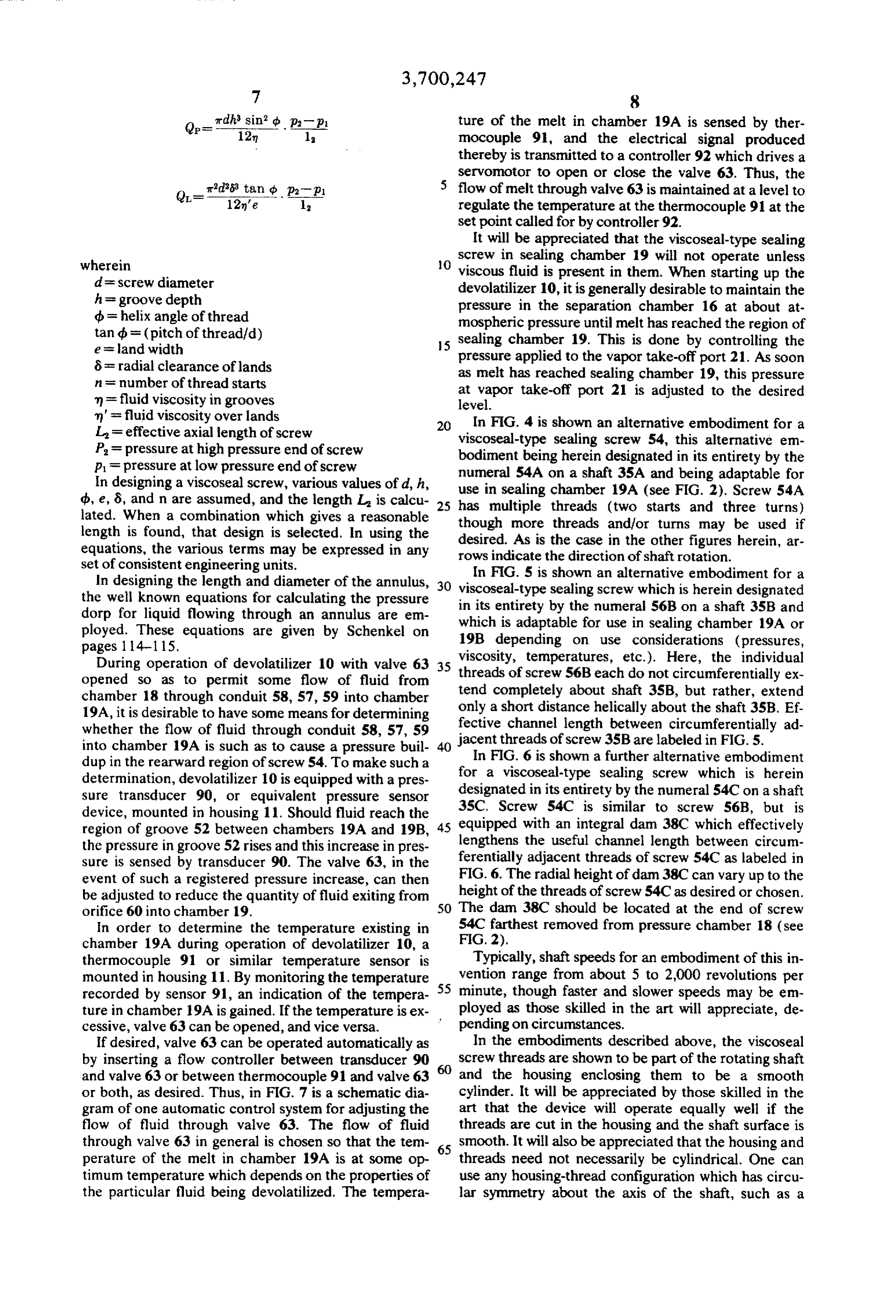
Because in the operation of devolatilizer 10 there is a Q = Q - O - Q. possibility that the rate of fluid egress from orifice 60 wherein will be such as to be in excess of that which screw 54 will pump back into chamber 18, there is the possibility O (the drag flow) is the axial flow from low to high of an "overflow' situation occurring where in fluid will 55 pressure generated by the interaction of the screw ooze or flow out the rear (relative to chamber 18) of with its housing;
chamber 19A between shaft 35 and housing 11. To OP is the axial flow from high to low pressure along prevent escape of fluid so leaving chamber 19A, a the grooves as a result of the pressure gradient along the groove; and viscoseal-type sealing screw 56 is located in chamber 19B in the embodiment shown though a conventional 60 Qis the axial flow from high to low pressure over the screw lands as a result of pressure difference type of seal, such as a packing gland (not shown) could between adjacent grooves. be used, if desired, as those skilled in the art will readily These three terms may be calculated from the fol appreciate. Use of a seal here is entirely optional. lowing equations:
Screw 56 is used in the presently preferred embodi 65 ment shown of the present invention and has reverse threads (relative to the direction of shaft 35 rotation) Q Dr. r’d'hn sin2 d cos d which, when shaft 35 rotates and fluid is in the region
Page 9
ture of the melt in chamber 19A is sensed by ther mocouple 91, and the electrical signal produced thereby is transmitted to a controller 92 which drives a servomotor to open or close the valve 63. Thus, the
Q rds tan is p2p flow of melt through valve 63 is maintained at a level to 12'e l regulate the temperature at the thermocouple 91 at the set point called for by controller 92.
It will be appreciated that the viscoseal-type sealing wherein O screw in sealing chamber 19 will not operate unless d = screw diameter viscous fluid is present in them. When starting up the h = groove depth devolatilizer 10, it is generally desirable to maintain the ob = helix angle of thread pressure in the separation chamber 16 at about at mospheric pressure until melt has reached the region of tandb = (pitch of thread/d) 5 sealing chamber 19. This is done by controlling the e = land width pressure applied to the vapor take-off port 21. As soon 6= radial clearance of lands n = number of thread starts as melt has reached sealing chamber 19, this pressure m = fluid viscosity in grooves at vapor take-off port 21 is adjusted to the desired level.
m' = fluid viscosity over lands In FIG. 4 is shown an alternative embodiment for a L = effective axial length of screw viscoseal-type sealing screw 54, this alternative em P = pressure at high pressure end of screw bodiment being herein designated in its entirety by the p = pressure at low pressure end of screw numeral 54A on a shaft 35A and being adaptable for In designing a viscoseal screw, various values of d, h, use in sealing chamber 19A (see FIG. 2). Screw 54A db, e, 8, and n are assumed, and the length L is calcu 25 has multiple threads (two lated. When a combination which gives a reasonable though more threads and/orstarts turns and three turns) may be used if length is found, that design is selected. In using the desired. As is the case in the other figures equations, the various terms may be expressed in any rows indicate the direction of shaft rotation. herein, ar set of consistent engineering units. In FIG. 5 is shown an alternative embodiment for a In designing the length and diameter of the annulus, viscoseal-type sealing screw which is herein designated the well known equations for calculating the pressure in its entirety by dorp for liquid flowing through an annulus are em which is adaptablethefornumeral use in 56B on a shaft 35B and sealing chamber 19A or ployed. These equations are given by Schenkel on 19B depending on use considerations (pressures,
During operation of devolatilizer 10 with valve 63 35 viscosity, temperatures, etc.). Here, the individual opened so as to permit some flow of fluid from threads of screw 56B each do not circumferentially ex chamber 18 through conduit 58, 57, 59 into chamber only tend completely about shaft 35B, but rather, extend 19A, it is desirable to have some means for determining fectivea short distance helically about the shaft 35B. Ef channel length between circumferentially ad whether the flow of fluid through conduit 58, 57, 59 40 jacent threads of screw 35B are labeled in FIG. 5. into chamber 19A is such as to cause a pressure buil dup in the rearward region of screw 54. To make such a forIn aFIG. 6 is shown a further alternative embodiment viscoseal-type sealing screw which is herein determination, devolatilizer 10 is equipped with a pres sure transducer 90, or equivalent pressure sensor designated in its entirety by the numeral 54C on a shaft device, mounted in housing 11. Should fluid reach the 35C. Screw S4C is similar to screw S6B, but is equipped with an integral dam 38C which effectively region of groove 52 between chambers 19A and 19B, 45 the pressure in groove 52 rises and this increase in pres lengthens the useful channel length between circum sure is sensed by transducer 90. The valve 63, in the ferentially adjacent threads of screw 54C as labeled in event of such a registered pressure increase, can then FIG. 6. The radial height of dam 38C can vary up to the be adjusted to reduce the quantity of fluid exiting from height of the threads of screw 54C as desired or chosen. orifice 60 into chamber 19. SO The dam 38C should be located at the end of screw In order to determine the temperature existing in 54C farthest removed from pressure chamber 18 (see chamber 19A during operation of devolatilizer 10, a FIG. 2).
thermocouple 91 or similar temperature sensor is Typically, shaft speeds for an embodiment of this in mounted in housing 11. By monitoring the temperature 55 vention range from about 5 to 2,000 revolutions per recorded by sensor 91, an indication of the tempera minute, though faster and slower speeds may be em ture in chamber 19A is gained. If the temperature is ex ployed as those skilled in the art will appreciate, de pending on circumstances.
cessive, valve 63 can be opened, and vice versa.
If desired, valve 63 can be operated automatically as In the embodiments described above, the viscoseal by inserting a flow controller between transducer 90 60 screw threads are shown to be part of the rotating shaft and valve 63 or between thermocouple 91 and valve 63 and the housing enclosing them to be a smooth or both, as desired. Thus, in FIG. 7 is a schematic dia cylinder. It will be appreciated by those skilled in the gram of one automatic control system for adjusting the art that the device will operate equally well if the flow of fluid through valve 63. The flow of fluid threads are cut in the housing and the shaft surface is through valve 63 in general is chosen so that the tem 65 smooth. It will also be appreciated that the housing and perature of the melt in chamber 19A is at some op threads need not necessarily be cylindrical. One can timum temperature which depends on the properties of use any housing-thread configuration which has circu the particular fluid being devolatilized. The tempera lar symmetry about the axis of the shaft, such as a
Page 10
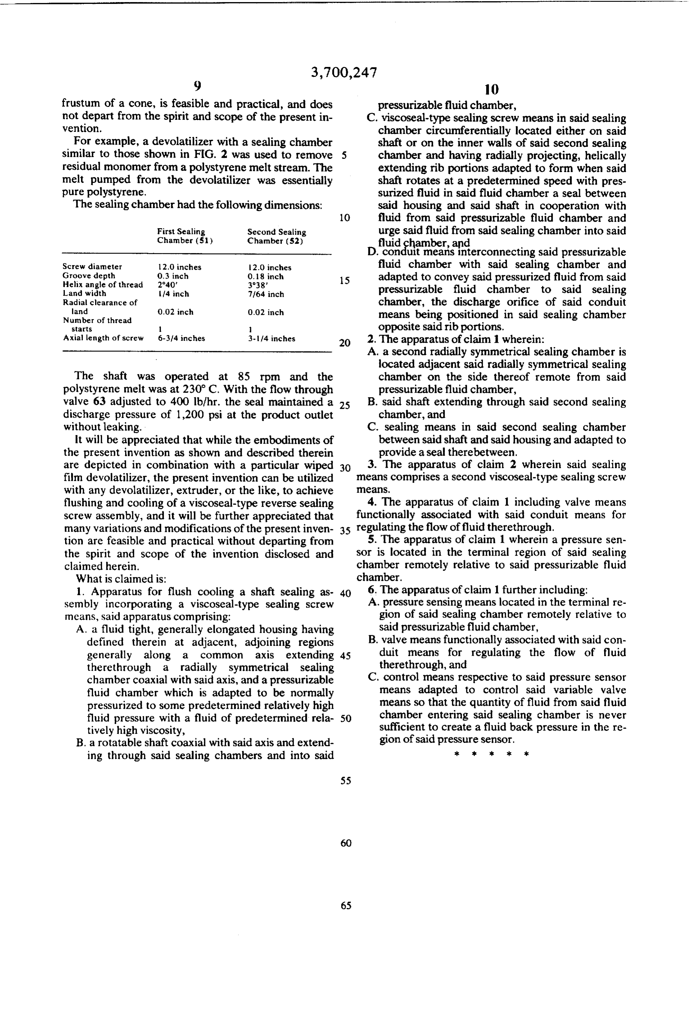
frustum of a cone, is feasible and practical, and does pressurizable fluid chamber, not depart from the spirit and scope of the present in C. viscoseal-type sealing screw means in said sealing vention. chamber circumferentially located either on said For example, a devolatilizer with a sealing chamber shaft or on the inner walls of said second sealing similar to those shown in FIG. 2 was used to remove chamber and having radially projecting, helically residual monomer from a polystyrene melt stream. The extending rib portions adapted to form when said melt pumped from the devolatilizer was essentially shaft rotates at a predetermined speed with pres pure polystyrene. surized fluid in said fluid chamber a seal between The sealing chamber had the following dimensions: said housing and said shaft in cooperation with O fluid from said pressurizable fluid chamber and
First Sealing
Chamber (S1)
Second Sealing urge said fluid from said sealing chamber into said
Sfgchamber, and
Chambet (S2)
Heisterconnecting said pressurizable
Screw diameter 12.0 inches 2.0 inches fluid chamber with said sealing chamber and Groove depth
Helix angle of thread 0.3 inch
0.8 inch 3°38' 5 adapted to convey said pressurized fluid from said
Landwidth 14 inch 71.64 inch pressurizable fluid chamber to said sealing Radial clearance of
chamber, the discharge orifice of said conduit
Number of thread means being positioned in said sealing chamber starts l opposite said rib portions. Axial length of screw 6-314 inches 3-14 inches 2. The apparatus of claim 1 wherein: A. a second radially symmetrical sealing chamber is located adjacent said radially symmetrical sealing
The shaft was operated at 85 rpm and the chamber on the side thereof remote from said polystyrene melt was at 230 C. With the flow through pressurizable fluid chamber, valve 63 adjusted to 400 lb/hr. the seal maintained a 25 B. said shaft extending through said second sealing discharge pressure of 1,200 psi at the product outlet chamber, and without leaking. C. sealing means in said second sealing chamber It will be appreciated that while the embodiments of between said shaft and said housing and adapted to the present invention as shown and described therein provide a seal therebetween. are depicted in combination with a particular wiped 3. The apparatus of claim 2 wherein said sealing film devolatilizer, the present invention can be utilized means comprises a second viscoseal-type sealing screw with any devolatilizer, extruder, or the like, to achieve eans.
flushing and cooling of a viscoseal-type reverse sealing 4. The apparatus of claim 1 including valve means screw assembly, and it will be further appreciated that functionally associated with said conduit means for many variations and modifications of the present inven 35 regulating the flow of fluid therethrough. tion are feasible and practical without departing from 5. The apparatus of claim 1 wherein a pressure sen the spirit and scope of the invention disclosed and sor is located in the terminal region of said sealing claimed herein. chamber remotely relative to said pressurizable fluid What is claimed is: chamber.
1. Apparatus for flush cooling a shaft sealing as 40 6. The apparatus of claim 1 further including: sembly incorporating a viscoseal-type sealing screw A. pressure sensing means located in the terminal re means, said apparatus comprising: gion of said sealing chamber remotely relative to A. a fluid tight, generally elongated housing having said pressurizable fluid chamber, defined therein at adjacent, adjoining regions B. valve means functionally associated with said con generally along a common axis extending 45 duit means for regulating the flow of fluid therethrough a radially symmetrical sealing therethrough, and chamber coaxial with said axis, and a pressurizable C. control means respective to said pressure sensor fluid chamber which is adapted to be normally means adapted to control said variable valve pressurized to some predetermined relatively high means so that the quantity of fluid from said fluid fluid pressure with a fluid of predetermined rela 50 chamber entering said sealing chamber is never tively high viscosity, sufficient to create a fluid back pressure in the re B. a rotatable shaft coaxial with said axis and extend gion of said pressure sensor. ing through said sealing chambers and into said 3k k k ck k
Provenance
- Collection
- Cited prior art
- Original PDF
- patentimages.storage.googleapis.com →
- Filed
- 1971-08-16
- Pages
- 10
- Method
- pdftotext (the PDF's own text layer) + pdftoppm 300dpi page scans
- Source
- Google Patents bibliographic record
- Granted
- 1972-10-24
- Inventors
- Robert G Butler; Don E Carter; George A Latinen; MAY V LATINEN; Monsanto Co
- Transcribed from
- patentimages.storage.googleapis.com →