patent · US4482831
Magneto arrangement
13 November 1984
Page 1 — bibliographic record
United States Patent (19) 11 Patent Number: 4,482,831 Notaras et al. 45 Date of Patent: Nov. 13, 1984 (54) MAGNETO ARRANGEMENT 2,985,779 5/1961 Flaningam .......................... 30/153 3,828,426 8/1974 Phelon .................................. 30/42 76 Inventors: John A. Notaras; Angelo L. Notaras, 4,179,634 12/1979 Burson ................................ 310/156 both of 15 Reynolds St., Balmain, 4,404,513 9/1983 Campen .............................. 310/153 New South Wales, 2041, Australia
FOREIGN PATENT DOCUMENTS
189852 5/1957 Austria ................................ 310/153 22 Filed: Mar. 29, 1983 2062486 7/1972 Fed. Rep. of Germany ...... 310/156 30 Foreign Application Priority Data Primary Examiner-R. Skudy
Apr. 5, 1982 AU Australia ............................... PF3484 Attorney, Agent, or Firm-Ladas & Parry 51) Int. Cl. ............................................. H02K 21/12 57 ABSTRACT 52 U.S.C. ...................................... 310/156; 310/74; A magneto rotor assembly is disclosed in which a mag 310/153; 123/149 R net is clamped in position between a pair of pole pieces
310/42, 168; 74/572; 123/149 R, 149 D; within a cavity in a rotor. The pole pieces are provided 324/146; 29/598, 607 with at least one tapered surface which engages a or the
corresponding tapered surface(s) of the rotor cavity to prevent movement of the pole pieces and magnet. A
1,916,700 7/1933 Walther ............................... 310/153 engagement with the rotor cavity.
2,060,259 11/1936 Spengler ....... ... 310/156 2,756,356 7/1956 Brownlee ............................ 310/156 7 Claims, 10 Drawing Figures
Page 2
Drawing sheet — no readable text.
Page 3
Drawing sheet — no readable text.
Page 4
Drawing sheet — no readable text.
Page 5
Drawing sheet — no readable text.
Page 6
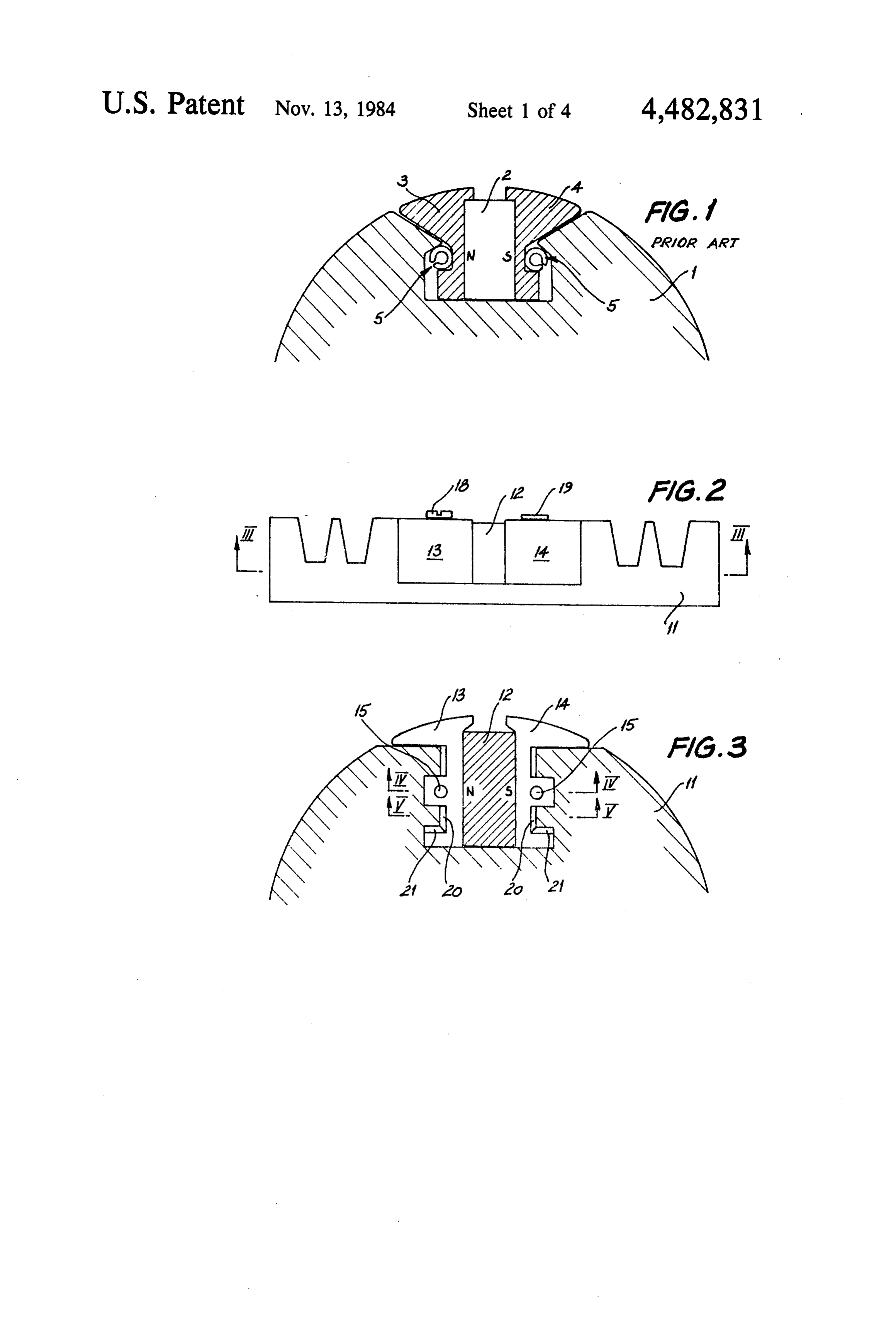
FIG. 1 illustrates the magneto construction used in
MAGNETo ARRANGEMENT four stroke motors in which a cast aluminium fly wheel 1 has mounted therein a ceramic magnet 2 which is
The present invention relates to magnetos for internal retained between two sintered pole pieces 3 and 4. The combustion engines and, in particular, to the assembly 5 pole pieces 3 and 4 are each respectively held in position of the magnet and pole pieces within the rotor of a by a split dowel 5 which is forced between the pole magneto. piece 3, 4 and the fly wheel 1. It is known from U.S. Pat. No. 4,179,634, for exam The split dowel 5 comprises a hollow metal tube with ple, to assemble a ceramic magnet between two sintered a longitudinally extending slot therein which is capable pole pieces and retain the pole pieces held within a cast 10 of resilient deformation so as to reduce the diameter of . rotor by means of split dowels.
This arrangement has the very great advantage of the dowel 5. It will be apparent that the resilience of the dowel 5 holds the pole pieces 3, 4 against the magnet 2 ease of assembly thereby reducing the manufactured and also prevents both sideways (that is, along a cord) cost of the rotor and magneto assembly, however, this movement of the pole pieces and radial movement of arrangement suffers from the disadvantage that the split 15 the pole pieces. The pole pieces 3,4 and magnet 2 are dowels are inclined to deform under inertial loads at restrained against movement into and out of the plane of high rotor speeds thereby causing the pole pieces to the paper by means of the frictional force present be move slightly radially outwardly at high speed. tween the split dowels 5, pole pieces 3,4 and fly wheel This disadvantage can be catered for in the design of 1.
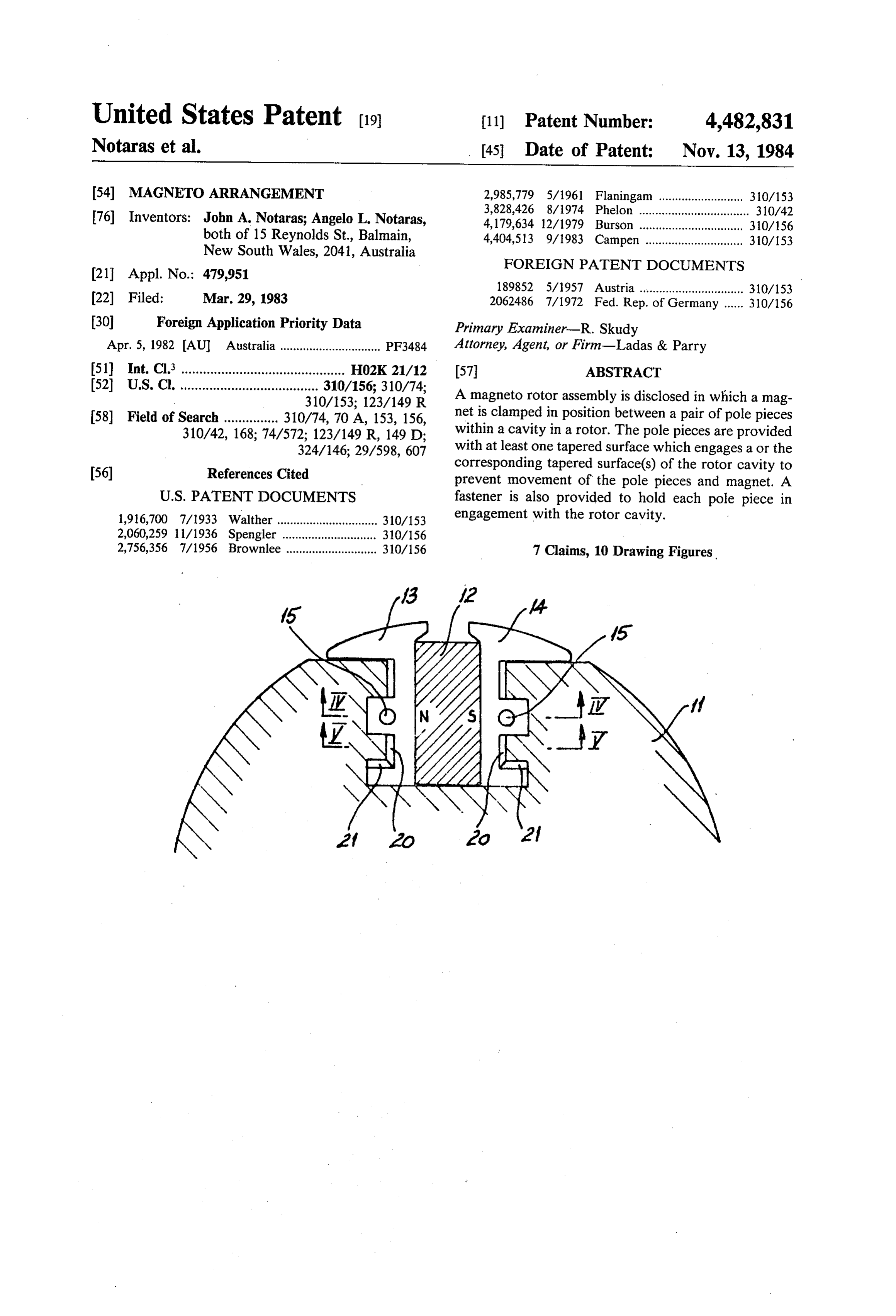
the internal combustion engine, however, the resulting 2O The arrangement illustrated in FIG. 1 has many man machine must have a relatively large air gap in order to ufacturing advantages in as much as low cost compo cater for the expected movement of the pole pieces at nents are able to be utilised and the arrangement is able high speed. In consequence, the magnetic and electrical to be easily assembled. However, in operation the as performance of the magneto is reduced at low speeds sembly of FIG. 1 suffers from the disadvantage that at owing to the increased reluctance of the magneto mag 25 high speed the fly wheel 1 experiences an extreme, netic circuit brought about by the relatively large air radially directed, inertial force. This force tends to com gap. press the dowels 5 and thereby allow the pole pieces 3,4 It is the object of the present invention to provide an to move radially outward. In consequence, the air gap improved magneto construction which overcomes, or of the machine must be larger than would otherwise be substantially ameliorates, the abovementioned disad 30 the case if the pole pieces 3,4 where absolutely fixed. vantage. Thus, the electrical performance of the magneto incor According to one aspect of the present invention porated in the structure of FIG. 1 is degraded, espe there is disclosed a magneto rotor assembly in which a cially at low speed.
magnet is maintained in position between a pair of pole 35 In accordance with the preferred embodiment of the pieces within a cavity in said rotor, wherein said pole present invention, the abovementioned disadvantage is pieces are provided with at least one tapered surface overcome by securely holding the pole pieces in three and said cavity has at least one tapered surface corre mutually perpendicular directions.
sponding to each pole piece, said pole piece and rotor As illustrated in FIGS. 2-5 inclusive, in accordance cavity tapered surfaces being mutually engagable to with the preferred embodiment, the fly wheel 11 re clamp said pole pieces against said magnet within said ceives a ceramic magnet 12 held between sintered pole rotor wherein a fastener holds each pole piece in en pieces 3, 4, generally as before. However, the pole gagement with said rotor and wherein the direction of pieces 13, 14 are each provided with an aperture 15 clamping of said tapered surfaces is substantially per through which the shank of a fastener 16 extends. As pendicular to the longitudinal axis of said fastener. 45 best seen in FIG.4, the fastener 16 can be either a nut 17 Four embodiments of the present invention will now and bolt 18 or a knurled rivet 19.
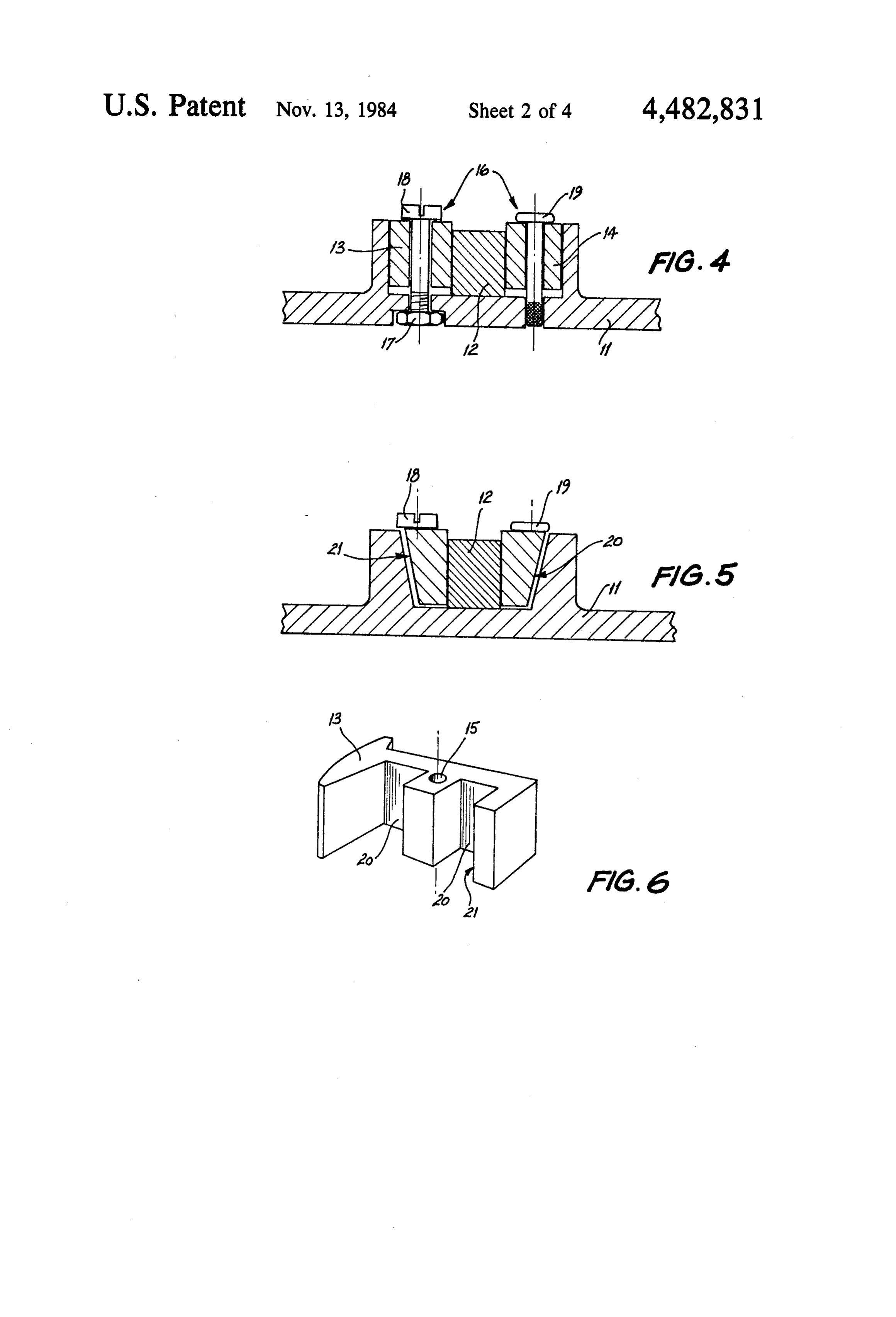
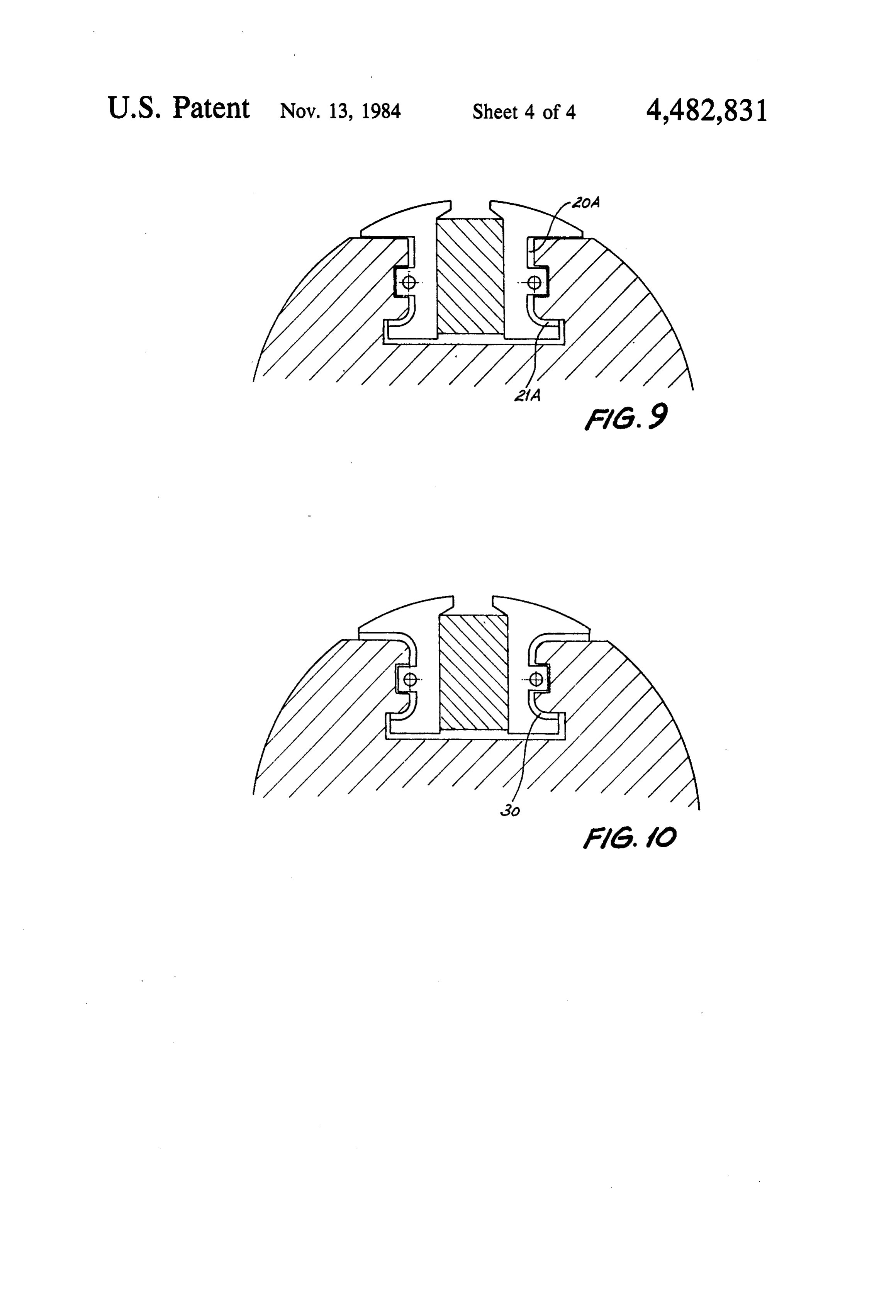
be described with reference to the drawings in which: In addition, as best seen in FIGS. 3 and 5, the pole FIG. 1 is a schematic plan view of the prior art ar pieces 13, 14 are provided with two tapered surfaces 20 rangement of U.S. Pat. No. 4,179,634; and 21 the normals of which are substantially "mutually FIG. 2 is a side elevation of the rotor having the 50 perpendicular". Preferably the degree of taper is rela magneto construction of a first preferred embodiment; tively slight, preferably of the order of approximately 5 FIG. 3 is a cross sectional view taken along line III degrees, thus the normal to the "notional surface' -III of FIG. 2; which is tapered at, say, 5 degrees in order to produce FIG. 4 is a cross sectional view taken along the line the actual tapered surface, is mutually perpendicular to IV-IV of FIG. 3; 55 the normal passing through the other notional surface FIG. 5 is a further cross sectional view taken along and also substantially perpendicular to the longitudinal the line V-V of FIG. 3; axis of the fastener 16.
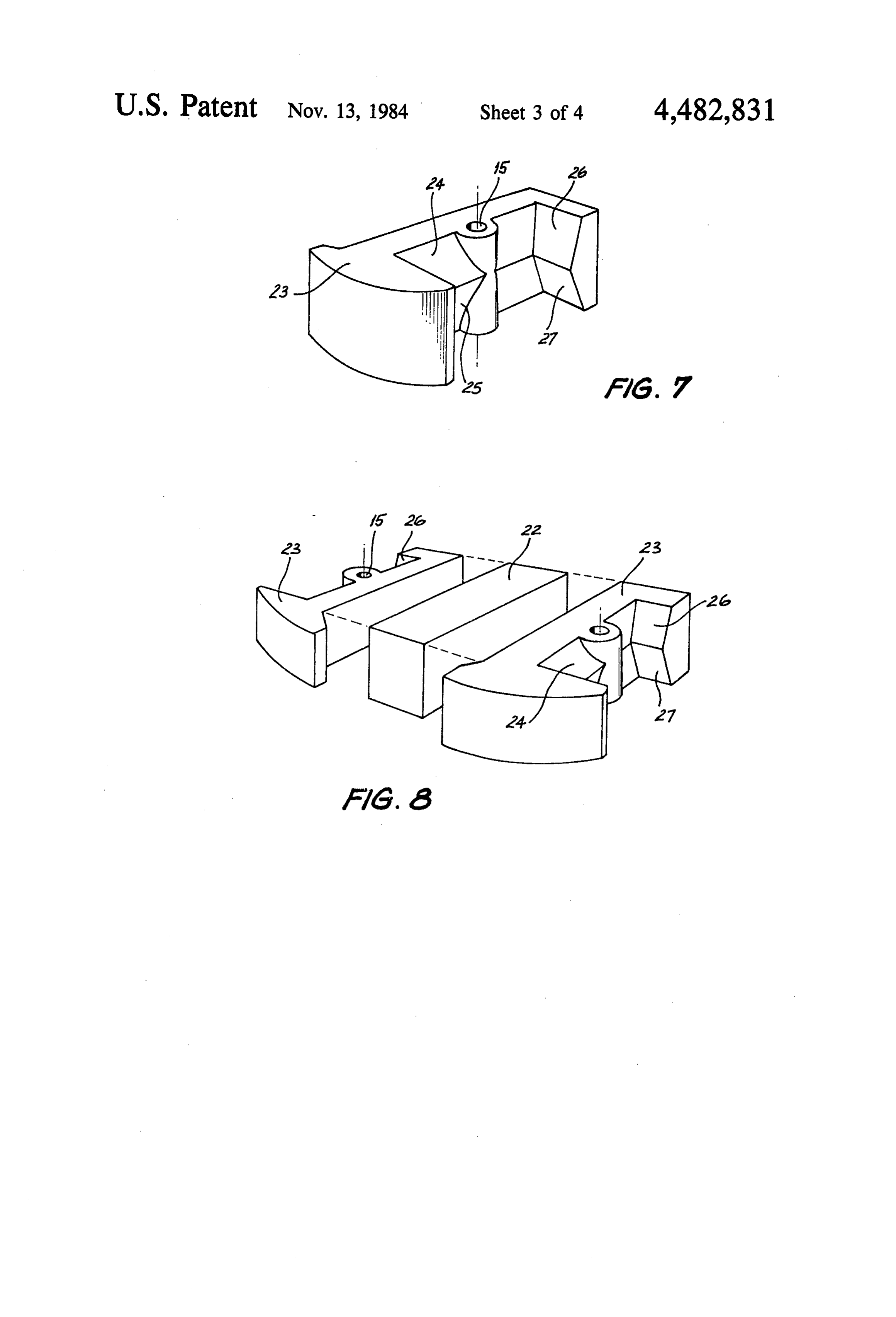
FIG. 6 is a perspective view of one of the pole pieces It will be apparent from FIG. 3 that the tapered sur of FIGS. 2 and 3; face 20 which extends in the radial direction holds the FIG. 7 is a view similar to FIG. 6 but of a pole piece 60 pole pieces 13, 14 against outward movement away of a second embodiment; from the magnet 12 along the "chord' which forms the FIG. 8 is an exploded perspective view of two pole line joining apertures 15. Similarly, the tapered surface pieces and a magnet in accordance with the embodi 21 holds the pole pieces 13, 14 against radial movement ment of FIG. 7; during rotation of the fly wheel 11. Each of the pole FIG. 9 is a view similar to FIG. 3 but of a third en 65 pieces 13, 14 includes a substantially flat portion (not bodiment; and identified in the drawings).
FIG. 10 is a view similar to FIG. 9 but of a fourth It will be appreciated in considering FIG. 6 that since embodiment, the degree of taper of the tapered surfaces 20, 21 is
Page 7
normally very slight, the taper is not very apparent in those skilled in the art, may be made thereto without FIG. 6. departing from the scope of the present invention. For It will be apparent that during assembly each of the example, the aperture 15 can take the form of an open pole pieces 13 and 14 is located within the rotor 11, then sided slot.
the magnet 12 is positioned between the pole pieces 13, 5 What we claim is:
14 which are raised as seen in FIG. 5 or moved away 1. A magneto rotor assembly in which a magnet is from the rotor 11. maintained in position between a pair of pole pieces Then the fasteners 16 are secured forcing the pole within a cavity in said rotor, said pole pieces are pro pieces 13, 14 towards the rotor 11 and clamping the vided with two tapered surfaces and said cavity is pro magnet 12 in place to ensure both a low reluctance 10 vided with two corresponding tapered surfaces, one of magnetic path and that the magnet 12 and pole pieces said tapered surfaces extending in a radial direction to 13, 14 are secured. Naturally the apertures 15 are of hold said pole pieces against outward movement away slightly larger diameter than the shanks of the fasteners from said magnet and the other of said tapered surfaces 16 to permit this clamping action. holding said pole pieces against radial movement each FIGS. 7 and 8 illustrate a second embodiment of the 15 said pole piece and said rotor cavity tapered surfaces present invention in which a single pole piece 23 can be being mutually engagable to clamp said pole pieces utilized to either side of a magnet 22 by merely revers against said magnet within said rotor wherein a fastener ing the pole piece 23. This facility is bought about be holds each pole piece in engagement with said rotor cause the pole piece 23 is doubly tapered having radial said two tapered surfaces having normals which are surfaces 24 and 25 which abut each other and taper in 20 substantially mutually perpendicular and lie approxi opposite directions and also having chord surfaces 26, mately in a plane and which is substantially perpendicu 27 which abut each other and which also taper in oppo site directions. Again, the pole pieces 23 is provided lar2.toAthemagneto longitudinal axis of said fastener.
with an aperture 15 through which a fastener (not illus wherein each saidrotor assembly as claimed in claim 1 trated) is able to pass, the fastener being "perpendicu- 25 is substantially flat and acomprises pole a first portion which second portion which is gener lar' to the "normal' passing through the radial surfaces ally curved.
24.25 and also "perpendicular" to the "normal" passing 3. A magneto rotor assembly as claimed in claim 1 through the chord surfaces 26, 27. The arrangement of wherein each of said pole pieces has a single tapered FIGS. 7 and 8 reduces the number of different parts required for the assembly. The tapered surfaces 24, 25 30 surface which is curved to form a quasi-semi-circular can be made substantially equal, and the pole pieces 23 tapered surface.
4. A magneto rotor assembly as claimed in claim 1 are substantially identical.
FIG. 9 illustrates a third embodiment, in a manner wherein said tapered surfaces of each of said pole pieces similar to FIG. 3. The tapered surface 20A which ex are tapered in two substantially opposite directions. tends in the radial direction is as before but smoothly 35 5. A magneto rotor assembly as claimed in claim 4 transforms to become curved chord tapered surface wherein said opposite tapered surfaces are substantially 21A which extends in the chord direction. In the fourth equal and both said pole pieces are substantially identi embodiment illustrated in FIG. 10 the radial and chord cal.
direction tapered surfaces are merged into a quasi-semi 6. A magneto rotor assembly as claimed in claim 1 circular tapered surface 30. In these two latter embodi- 40 mately 5 said wherein tapered surfaces have a taper of approxi degrees.
ments the tapered surfaces of the rotor have to be corre spondingly shaped. The reversible dual taper pole piece 7. A magneto rotor assembly as claimed in claim 1 of FIGS. 7 and 8 is also applicable to the curved tapered wherein each said fastener has a shank passing through surfaces of the pole pieces of FIGS. 9 and 10. an aperture in the corresponding pole piece, the size of The foregoing describes only four embodiments of 45 said aperture being greater than the width of said shank. the present invention and modifications, obvious to 4
Provenance
- Collection
- Cited prior art
- Original PDF
- patentimages.storage.googleapis.com →
- Filed
- 1983-03-29
- Pages
- 7
- Method
- pdftotext (the PDF's own text layer) + pdftoppm 300dpi page scans
- Source
- Google Patents bibliographic record
- Granted
- 1984-11-13
- Inventors
- John A. Notaras; Angelo L. Notaras
- Transcribed from
- patentimages.storage.googleapis.com →