patent · US4022479
Sealing rings
10 May 1977
Page 1 — bibliographic record
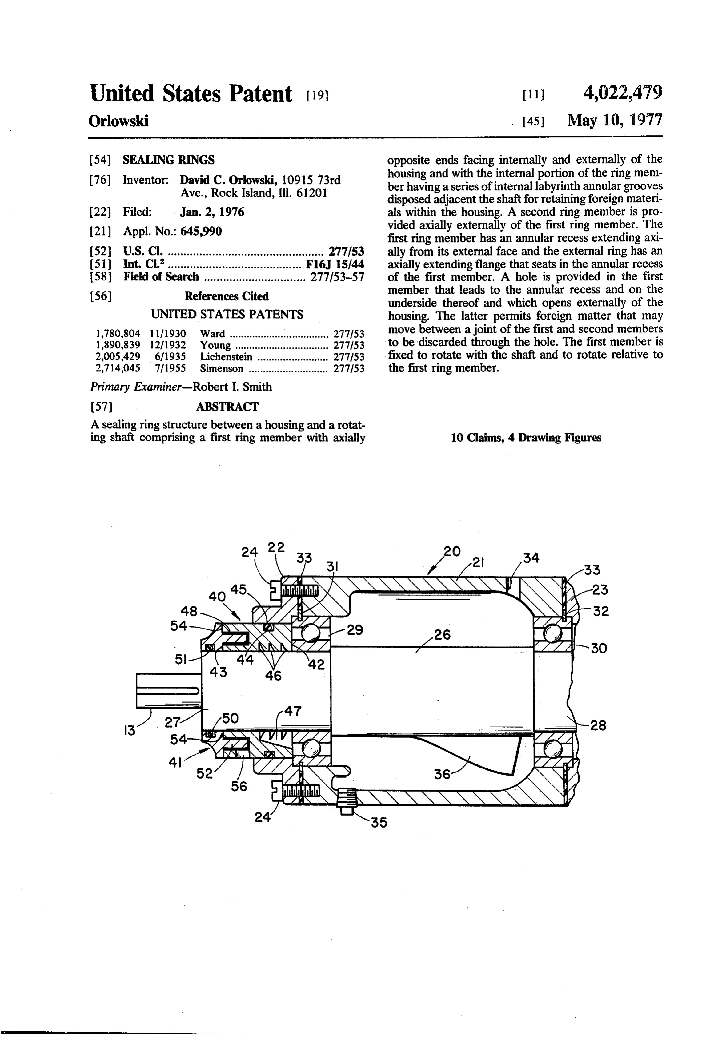
United States Patent (19) 11 4,022,479 Orlowski (45) May 10, 1977 54 SEALNG RINGS opposite ends facing internally and externally of the 76 Inventor: David C. Orkowski, 10915 73rd housing and with the internal portion of the ring mem Ave., Rock Island, Ill. 6120 ber having a series of internal labyrinth annular grooves disposed adjacent the shaft for retaining foreign materi 22 Filed: . Jan. 2, 1976 als within the housing. A second ring member is pro (21) Appl. No.: 645,990 vided axially externally of the first ring member. The first ring member has an annular recess extending axi 52 U.S.C. ................................................. 277/53 ally from its external face and the external ring has an 5) Int, C.'......................................... F16, 15144 axially extending flange that seats in the annular recess 58) Field of Search ................................ 277/53-57 of the first member. A hole is provided in the first 56) References Cited member that leads to the annular recess and on the underside thereof and which opens externally of the
UNITED STATES PATENTS housing. The latter permits foreign matter that may l,780,804 1 1/1930 Ward ................................... 277/53 move between a joint of the first and second members l,890,839 12/1932 Young ................................. 277/53 to be discarded through the hole. The first member is 2005,429 6/1935 Lichenstein ......................... 277.153 fixed to rotate with the shaft and to rotate relative to 2,714,045 7/1955 Simenson ............................ 277.153 the first ring member.
Primary Examiner-Robert I. Smith
A sealing ring structure between a housing and a rotat ing shaft comprising a first ring member with axially 10 Claims, 4 Drawing Figures
45 sian NS
ASANN
2ZZX4's NI 29, ()
a NAS
Page 2
Drawing sheet — no readable text.
Page 3
annular flange on the adjoining outer ring that fits
SEALNG RINGS within the annular recess of the first ring. There are sufficient tolerances provided between the recess and
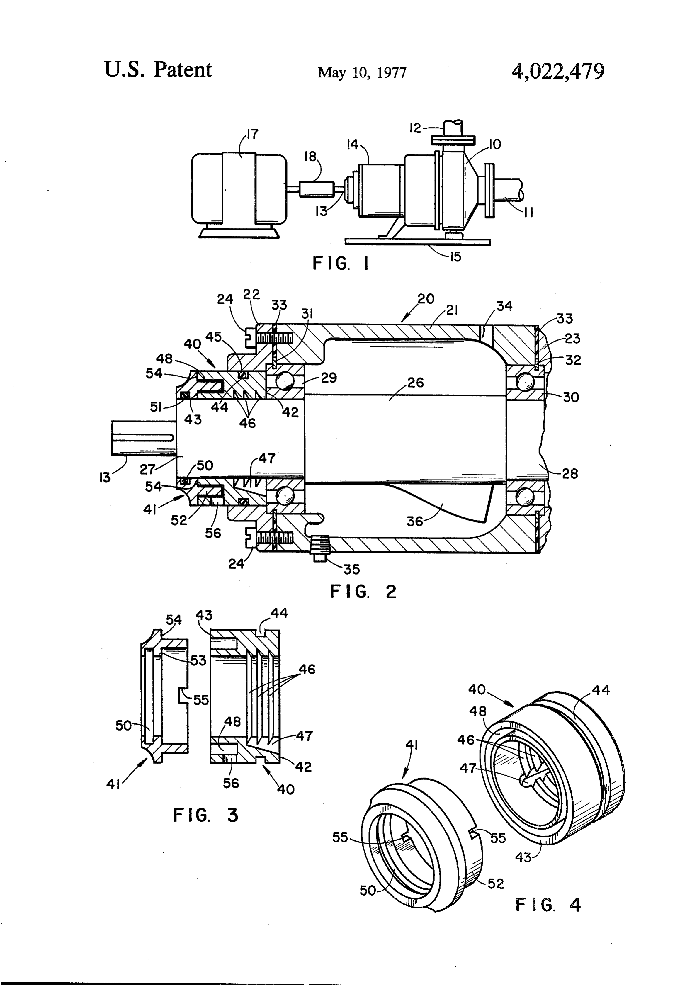
BACKGROUND OF THE INVENTION annular flange so that the two bearing rings that are In certain industries it is extremely important that 5 rotating relative to one another will not bind or create there be provided a seal for bearings that supports a heated frictional disposition between them. Provided rotating shafts which prevent the lubricants associated. in the first sealing ring is a hole that leads to its recess. with the bearings from leaking externally of an asso The annular flange of the second sealing ring has ciated housing or bearing support and for preventing notches cut therein. With such an arrangement foreign foreign particles in the environment which the shaft is O particles that may move in the joint formed by the being used from working itself through the seal and into recess and flanges will be scraped by the notches in the the lubricant for the bearing. Such an industry is the flanges to the hole where they will be discharged back food preparation industry in which it is extremely im into the atmosphere or the area surrounding the hous portant that the lubricant does not mix with the food ing. The first ring is, of course, fixed to the housing and particles and in which the food particles do not work 15 the second ring is, of course, fixed to rotate with the themselves into the bearings and lubricants. shaft by suitable sealing means. However, in both in It is heretofore been known to provide a metal seal stances there is not movement between the respective ing ring which is fixed to the bearing housing and has sealing rings and the portion it is fixed to which would internal labyrinth-type grooves therein which tend to normally create wear if the opposite occurred. scrape lubricants moving axially along the shaft and to 20 thereby prevent lubricants from moving externally of BRIEF DESCRIPTION OF THE DRAWINGS the housing. Conventionally with such a sealing ring FIG. 1 is a side view of a food processing pump in there is provided an external cap that is fixed to the which the sealing structure of the present invention housing and has a sealing ring that fits externally of the may be used.
aforementioned ring and which prevents material from 25 FIG. 2 is an enlarged vertical sectional view showing moving internally of the housing through the latter ring. the present sealing structure with a ball bearing shaft The difficulty with this type of arrangement is that and as taken at one end of the pump structure shown in there is no complete seal between the internal and FIG. 1.
external sides of the housing. The cap with its sealing FIG. 3 is a vertical sectional exploded view of the ring surrounding the shaft while limiting movement of 30 sealing parts showing them separated. material into the housing nevertheless does permit FIG. 4 is a perspective view of the parts shown in some material from moving into it. This type of seal is FIG. 3.
never completely acceptable since the shaft is rotating relative to the seal and eventually the seal wears. This, DESCRIPTION OF THE PREFERRED of course, permits foreign matter to enter into the hous 35 EMBODIMENT ing and to eventually damage the bearings. The life of Referring first to FIG. 1 showing an arrangement in the bearings is extremely long so long as they are prop which the present sealing structure can be used, there is erly lubricated and no foreign matter enters into the provided area. In the food industry, for example, in which large an intake inpipe a food processing plant, a pump 10 having 11 and a discharge pipe 12. The pump pumps handle the food, such pumps will in many in 10 is a conventional
impeller-type having a main drive stances operate twenty-four hours a day and continu shaft 3 that is carried in a bearing housing 14. Both ously from day to day. Because of this, when the bear the housing 14 and pump housing 10 are fixed to a ings do fail the entire line utilizing food products from common platform 15. An electric motor 17 is provided the pump must be shut down. Also, if for any reason the for driving a shaft 13 and a coupling lubricant for the bearings is permitted to move exter 45 connecting the motor shaft 17 to the18 is provided for pump drive shaft nally of the housing, the possibility of contaminating the food becomes greater and under normal procedure 13.Referring now to FIG. 2, the shaft 13 is provided with such a pump will be shut down until a new and suitable a bearing housing 20 composed of a central barrel seal is provided.
50 portion 21 and two end plates 22,23, the latter being
SUMMARY OF THE INVENTION fixed to the former by suitable bolts 24. The shaft 13 is With the above in mind, it is a primary object of the provided with an enlarged central portion 26 with re present invention to provide a sealing ring structure duced end portions 28,28, the latter having shoulders which practically eliminates the movement of the lubri with the enlarged portion 26 against which ball bear cant for the bearings outside of the housing. The seal 55 ings 29,30 may bear. The outer race of the bearings ing ring structure also practically eliminates the move 29.30 are provided with small annular slots that receive ment of foreign particles such as food particles into the snap rings 31,32 which generally hold the bearings bearing area and lubricant area within the housing. against axial movement. The snap rings 31,32 fit be More specifically, it is the object of the present in tween the end plates 22, 23 and the ends of the central vention to provide a sealing structure that is composed 60 barrel portion 21 of the housing. Suitable gaskets such of two rings, preferably metal, one of which is fixed to as at 33 are provided between the end plates 22,23 and the housing and the other of which is fixed to rotate the barrel portion 21 so as to prevent leakage of the with the shaft. The ring that is fixed to the housing has lubricant internally of the housing. The central barrel a labyrinth-type of seal against the shaft which prevents portion 21 is provided with a lubricant inlet 34 and a the lubricant from moving outside of the housing along 65 drain plug 35. Lubricant is normally filled in the hous the shaft. A joint is provided between the two rings ing 20 to a height so that it will penetrate into the bear which is composed of an annular recess in the first ring ings 29.30. A swash blade 36 is fixed to the shaft so as that opens axially outwardly of the housing and an to keep the lubricant agitated within the housing.
Page 4
In order to prevent leakage of the lubricant from externally of the housing and being fixed and sealed to inside the housing 20 outwardly and the leakage of the housing and having a series of internal labyrinth foreign particles from outside the housing into the annular grooves disposed adacent the shaft and an bearings or lubricant, there is provided a sealing ring axially extending groove joining the annular grooves structure composed of a first ring 40 and a mating and opening to said first end and in communication second ring 4l. The first ring 40 has axially opposite with the housing, said first ring member further having ends 42,43 facing internally of the housing 20 and an annular recess.extending axially from and opening externally of the housing respectively. The ring 40 also to said second end; and a second ring fixed to rotate has an external annular groove 44 in which seats an with the shaft and having an annular flange extending O-ring 45 that bears against a complementary circular O axially from inner and outer radial surfaces and opening in the end plate 22. The ring 40 is fixed against adapted for insertion in the annular recess with said rotation with respect to the housing 20 by a swedge fit radial surfaces bearing against the second end of the with respect to the plate 22. Three internal grooves 46 first ring member.
are provided on the inner surface of the ring 40 and 2. The invention defined in claim 1 further character provide radial shoulders which engage lubricant tend 15 ized by said first ring member having an opening on its ing to move axially outwardly along the shaft portion underside opening to the annular recess and externally 27 and to guide it into an axially extending groove on of the housing.
the underside of the ring 40. The groove 47 joins with 3. The invention defined in claim 3 further character the annular grooves 46 and oil that is caught in the ized by the first member having on its annular flange a grooves 46 will pass into the groove 47 and from there 20 slot that opens to the flange's outer surface and passes back into the housing 20. The end 43 of the ring 40 is adjacent the opening in the first ring member as the provided with an annular recess 48 that extends axially shaft rotates.
from the face 43 and serves one part of the joint with 4. The invention defined in claim 1 further character the second ring member or cap 41. ized by the second ring member having an internal The second or cap member 41 fits around the shaft 25 annular groove, and said second ring member is fixed portion 27 and has an internal annular groove 50 that to rotate with the shaft by means of an O-ring seated in carries an O-ring 51. The frictional engagement of the the latter groove and engaging the shaft. O-ring 51 between the cap 41 and the shaft portion 27 5. The invention defined in claim 1 further character causes the second ring member 41 to be fixed to rotate ized by the first ring having an external groove therein with the shaft 32. The O-ring also limits axial move 30 and an O-ring in said groove bearing against a housing ment of the member 41 on the shaft portion 27. The portion.
second ring or cap 41 is provided with an annular 6. A sealing structure for a shaft-carrying housing flange 52 that is complementary to and fits within the comprising: a pair of rings fixed respectively to the annular recess 48. The flange 52 extends axially from housing and the shaft, said rings being concentric with inner and outer radial faces 53,54 that are positioned 35 the shaft and having alongside the end 43 of the first ring 40. The annular faces with one of saidradially rings extending adjoining sur having an annular recess flange 52 is provided with a pair of diametrically oppo spaced radially from the shaft surface and extending site slots 55. A hole 56 is provided in the underside of axially from the aforesaid radially extending the first ring 40 and extends to the recess 48. It should surfaces and the other of said rings having anadjoining annular here be understood that the radial dimension of the 40 flange extending radially from the aforesaid radially flange 52 is from 0.005 inches to 0.015 inches smaller extending than the radial dimension of the recess 48. Conse adjoining surfaces and within the recess, said quently, the cap or ring 41 may rotate within the recess flange having at least one axially extending slot therein with practically zero friction between the respective and said ring having the recess therein also having an surfaces. 45 opening therein extending from the recess to outside Should foreign particles find their way into the junc the7.housing.
The invention defined in claim 6 further character tion of the ring 41 and ring 42, such particles must ized by the flange and recess being rectangular in cross move around the adjoining outer surfaces of the annu lar flange 52 and annular recess 48. However, particles section and having adjoining and complementary inner in this location will be swept or scraped by the edges of 50 and8. The outer axially extending annular surfaces.
invention defined in claim 7 in which the inner the slots 55 and will be moved to the opening 56 where the particles will gravitate externally of the housing 20. surfaces of the flange and recesses have a radial spacing Should any particles move around the end of the flange of at least 0.005 inches and the outer surfaces of the 48 to the inner surfaces of the flange 48, edges of the flange and recess have a radial spacng therebetween of slots 55 will again contact the particles and through the 55 at least 0.005 inches.
centrifical action of the cap 41 will be forced outwardly 9. The invention defined in claim 6 characterized by to the outer side of the flange 48 where they will again the ring that is fixed to the shaft is fixed thereto by an be swept through the opening 56. O-ring betwn the outer surface of the shaft and the It should here be noted that while O-rings 45,57 are inner surface of the ring.
provided for seals, there is no relative rotation between 60 10. The invention defined in claim 6 further charac the sealing surfaces of the O-rings. Therefore, the O terized by the ring that is fixed to the housing has inter rings 45,51 will not wear and the possibility of breaking nal annular grooves closely adjacent the shaft so that the seal at the O-rings is practically nonexistent. material moving along the shaft will catch in the I claim: grooves and further characterized by the internal 1. A ring seal between a fixed housing and a rotating 65 grooves having a passageway for moving the material shaft comprising: a first ring member having one end into the housing. k . k. k. k. k.
facing internally of the housing and a second end facing
Page 5
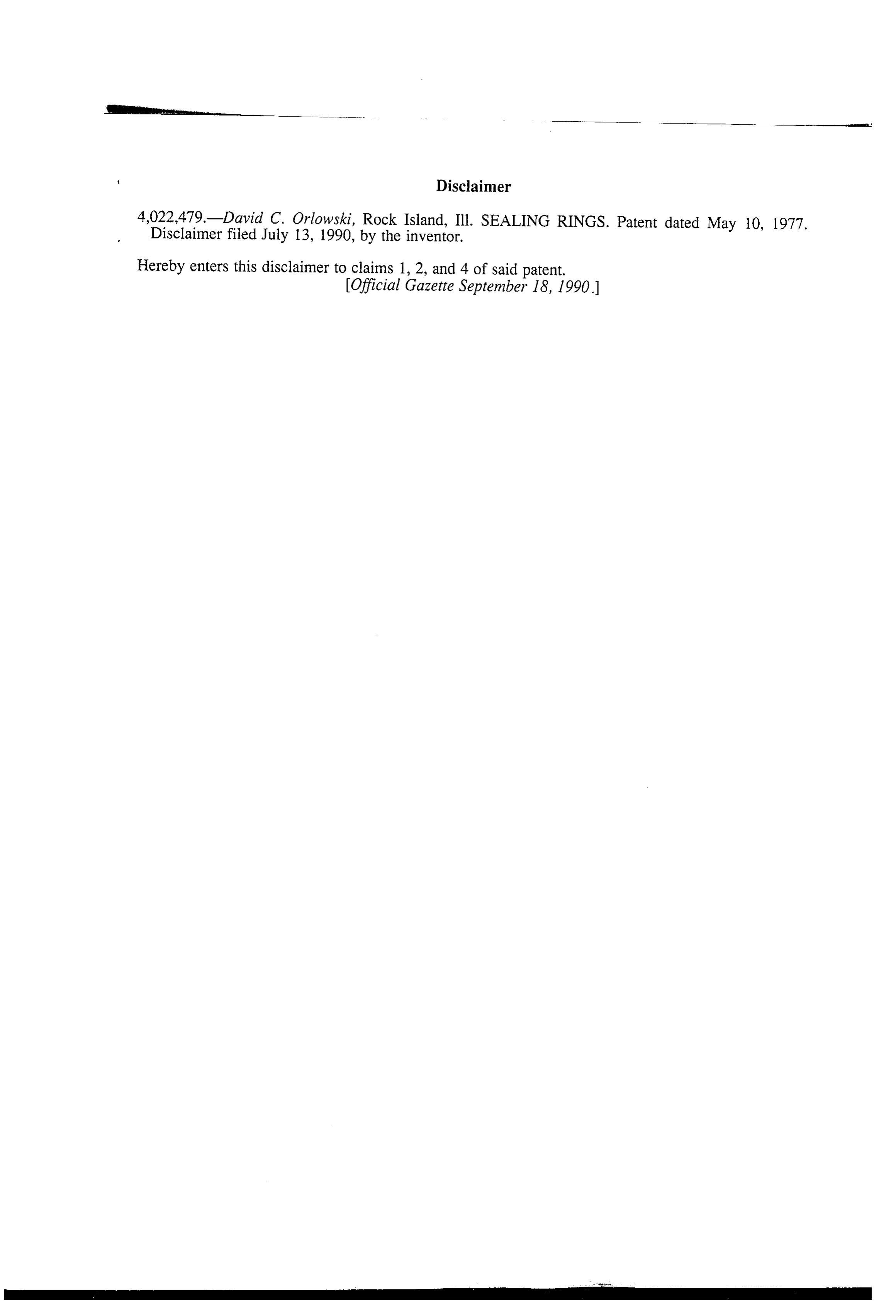
4,022.479-David C. Orlowski, Rock Island, Ill. SEALING RINGS. Patent dated May 10, 1977. Disclaimer filed July 13, 1990, by the inventor.
Hereby enters this disclaimer to claims 1, 2, and 4 of Said patent. Official Gazette September 18, 1990.)
Page 6
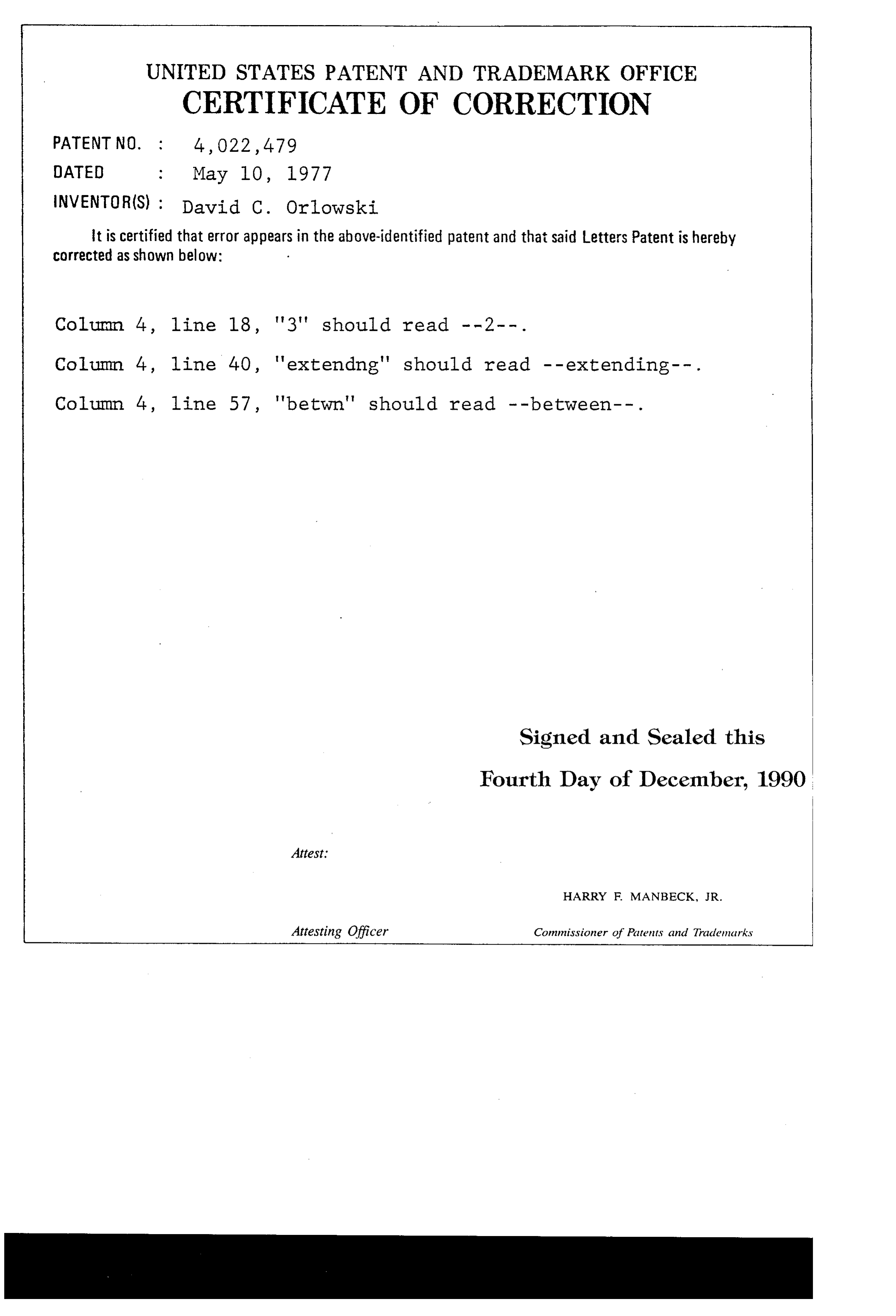
UNITED STATES PATENT AND TRADEMARK OFFICE
CERTIFICATE OF CORRECTION
INVENTOR(S) : David C. Oriowski it is certified that error appears in the above-identified patent and that said Letters Patent is hereby corrected as shown below:
Column 4, line 4-0, 'extending' should read -- extending--. Column 4, line 57, 'betwn' should read -- between -- . Signed and Sealed this
Fourth Day of December, 1990
Attest:
HARRY F. MANBECK, JR.
Attesting Officer Commissioner of Patents and Trademarks
Page 7
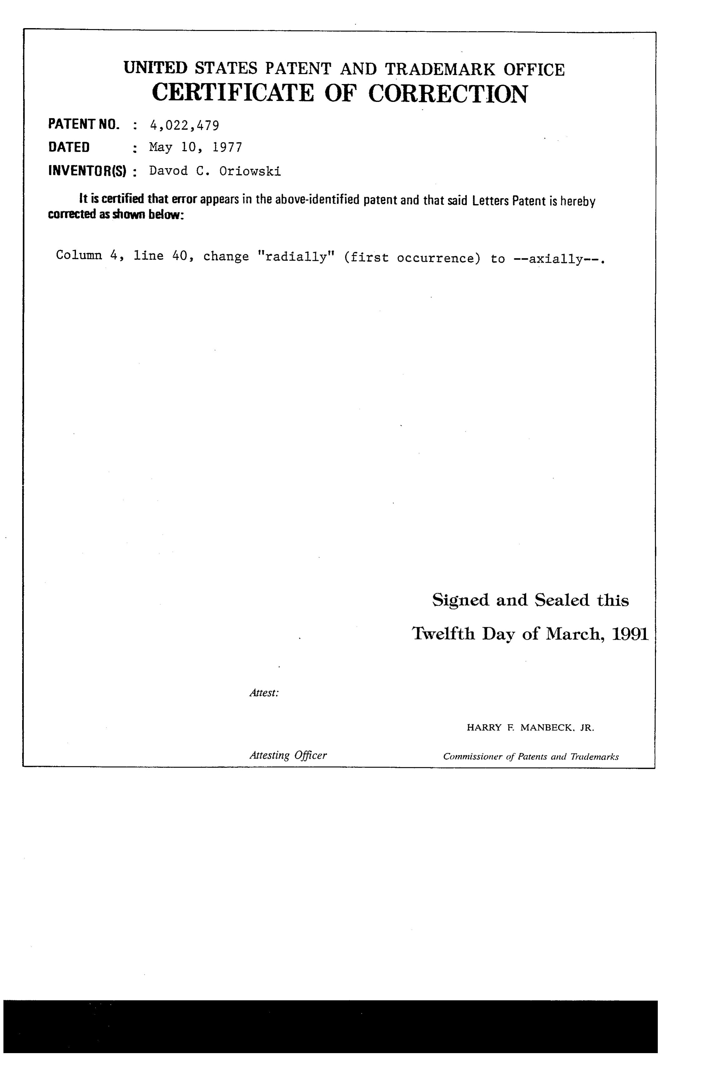
UNITED STATES PATENT AND TRADEMARK OFFICE
CERTIFICATE OF CORRECTION
INVENTOR(S) : Davod C. Oriowski it is certified that error appears in the above-identified patent and that said Letters Patent is hereby corrected as shown below:
Column 4, line 40, change "radially" (first occurrence) to -axially--. Signed and Sealed this
Twelfth Day of March, 1991
Attest:
HARRY F. MANBECK, JR.
Attesting Officer Commissioner of Patents and Trademarks
Provenance
- Collection
- Cited prior art
- Original PDF
- patentimages.storage.googleapis.com →
- Filed
- 1976-01-02
- Pages
- 7
- Method
- pdftotext (the PDF's own text layer) + pdftoppm 300dpi page scans
- Source
- Google Patents bibliographic record
- Granted
- 1977-05-10
- Inventors
- David C. Orlowski
- Transcribed from
- patentimages.storage.googleapis.com →