patent · US5298827
Permanent magnet type dynamoelectric machine rotor
29 March 1994
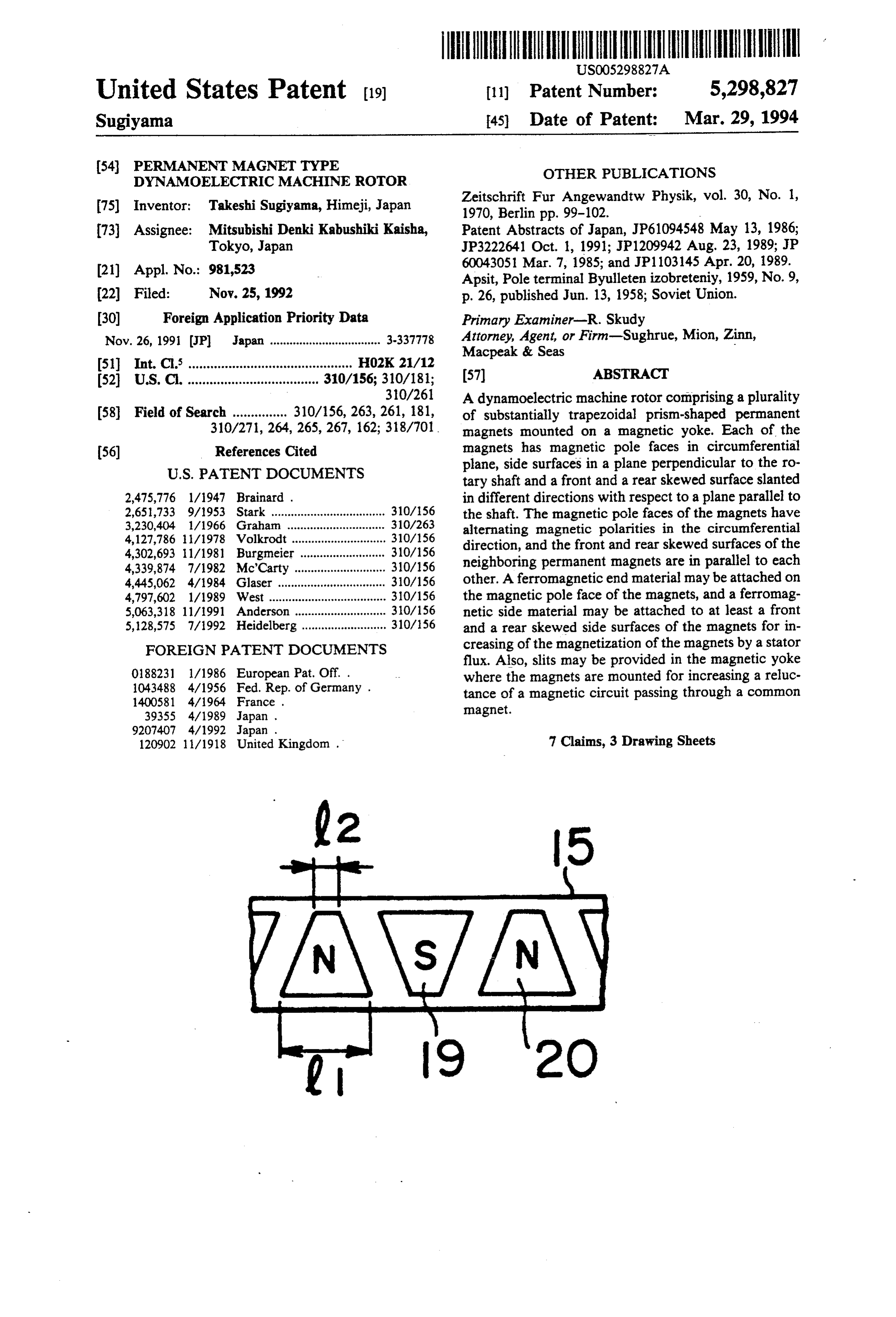
Page 1 — bibliographic record
United States Patent (19) 11) Patent Number: 5,298,827 Sugiyama 45 Date of Patent: Mar. 29, 1994 (54) PERMANENT MAGNET TYPE OTHER PUBLICATIONS
DYNAMOELECTRIC MACHINE ROTOR
(75) Inventor: Takeshi Sugiyama, Himeji, Japan Zeitschrift Fur Angewandtw Physik, vol. 30, No. 1,
73 Assignee: Mitsubishi Denki Kabushiki Kaisha, Patent Abstracts of Japan, JP61094.548 May 13, 1986; Tokyo, Japan JP3222641 Oct. 1, 1991; JP1209942 Aug. 23, 1989; JP (21) Appl. No.: 981,523 60043051 Mar. 7, 1985; and JP1103145 Apr. 20, 1989. Apsit, Pole terminal Byulleten izobreteniy, 1959, No. 9, (22) Filed: Nov. 25, 1992 p. 26, published Jun. 13, 1958; Soviet Union. (30) Foreign Application Priority Data Primary Examiner-R. Skudy Nov. 26, 1991 JP Japan .................................. 3.33.7778 Attorney, Agent, or Firm-Sughrue, Mion, Zinn,
51) Int. Cl. ............................................. HO2K 21/12 (57) ABSTRACT 52 U.S. C. .................................... 310/156; 310/181;
30/261 A dynamoelectric machine rotor comprising a plurality 58 Field of Search ............... 310/156, 263,261, 181, of substantially trapezoidal prism-shaped permanent 310/271, 264, 265,267, 162; 318/701. magnets mounted on a magnetic yoke. Each of the (56) References Cited magnets has magnetic pole faces in circumferential
plane, side surfaces in a plane perpendicular to the ro tary shaft and a front and a rear skewed surface slanted 2,475,776 l/1947 Brainard . in different directions with respect to a plane parallel to 2,651,733 9/1953 Stark ................................... 310/156 the shaft. The magnetic pole faces of the magnets have 3,230,404 1/1966 Graham .............................. 310/263 alternating magnetic polarities in the circumferential 4,127,786 il/1978 Volkrodt ............................. 310/156 direction, and the front and rear skewed surfaces of the 4,302,693 11/1981 Burgmeier .......................... 310/156 neighboring permanent magnets are in parallel to each 4,339,874 7/1982 McCarty ............................ 310/156 4,445,062 4/1984 Glaser ................................. 310/156 other. A ferromagnetic end material may be attached on 4,797,602 1/1989 West .................................... 310/156 the magnetic pole face of the magnets, and a ferromag 5,063,318 11/1991 Anderson ............................ 310/156 netic side material may be attached to at least a front 5,128,575 7/1992 Heidelberg .......................... 310/156 and a rear skewed side surfaces of the magnets for in FOREIGN PATENT DOCUMENTS creasing of the magnetization of the magnets by a stator flux. Also, slits may be provided in the magnetic yoke 0188231 1/1986 European Pat. Off. . where the magnets are mounted for increasing a reluc 1043488 4/1956 Fed. Rep. of Germany . tance of a magnetic circuit passing through a common 1400581 4/1964 France. magnet.
120902 11/1918 United Kingdom . 7 Claims, 3 Drawing Sheets
Page 2
Drawing sheet — no readable text.
Page 3
Drawing sheet — no readable text.
Page 4
Drawing sheet — no readable text.
Page 5
pole faces of permanent magnets for mechanically
PERMANENT MAGNET TYPE maintaining the permanent magnets on the magnetic DYNAMOELECTRIC MACHINE ROTOR yoke. The dynamoelectric machine rotor also com prises a plurality of permanent magnets mounted on the
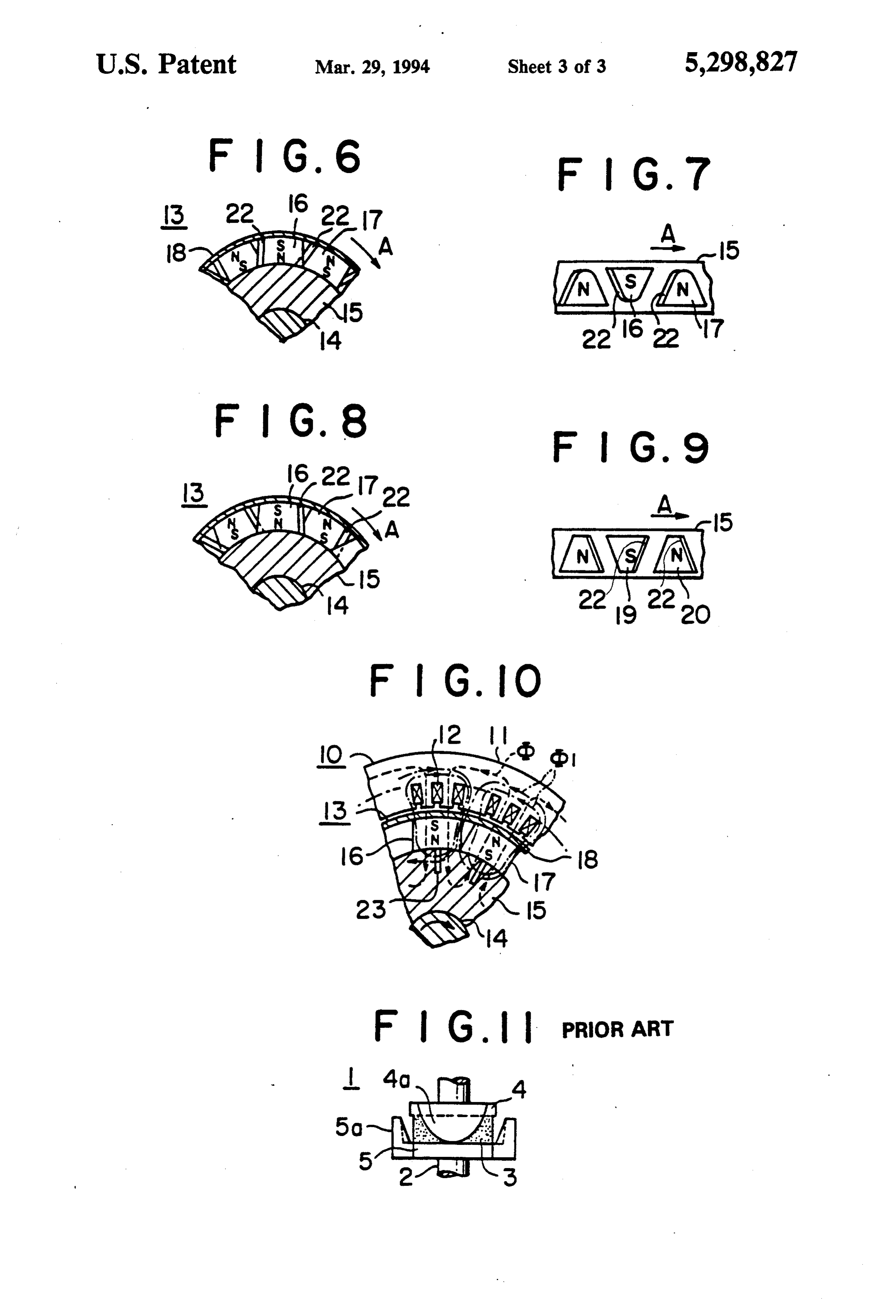
BACKGROUND OF THE INVENTION 5 magnetic yoke at a substantially equal radial dimension This invention relates to a dynamoelectric machine and substantially equal circumferential intervals with rotor and, more particularly, to a dynamoelectric ma respect to the central axis of the rotary shaft. Each of chine rotor with a permanent magnet type field magnets the permanent magnets having magnetic pole faces in a for use in a synchronous machine. circumferential plane, and the magnetic pole faces of FIG. 11 illustrates one example of a conventional O the permanent magnets having an alternating magnetic dynamoelectric machine rotor or permanent magnet polarities in the circumferential direction, and side sur type disclosed in Japanese Utility Model Laid-Open faces in a plane perpendicular to the central axis of the No. 3-39355. In FIG. 11, reference numeral 1 designates rotary shaft. The permanent magnet also has front and a rotor 1 in which a permanent magnet 3 magnetized in a rear skewed surfaces generally slanted in different an axial direction is secured on a rotary shaft 2. On the 15 direction with respect to a plane parallel to the central both sides of the permanent magnet 3, magnetic yokes 4 axis, and the front and rear skewed surfaces of neigh and 5 are secured to the rotary shaft 2. Claw poles 4a boring permanent magnets of the permanent magnets and 5a axially extend from the outer circumference of are parallel to each other.
the magnetic yokes 4 and 5. The axial dimension of a 20 Each of the permanent magnets may be substantially surface of the claw poles 4a and 5a facing to the station ary iron core (not shown) through an air gap is arranged prism-shaped and has a substantially trapezoidal cross to vary in a sine wave fashion in the circumferential section which may have a shorter side having a length direction. This causes the intersecting magnetic flux of from 27 to 40 percent of a length of a longer side. The passing through the stator winding (not shown) to vary 25 trapezoidal cross section may be rounded at its corners as a sine wave in accordance with the change of the of the shorter sides of the trapezoid. facing surface of the claw poles 4a and 5a. The dynamoelectric machine rotor may also have a In the conventional permanent magnet type rotor as ferromagnetic material attached between the magnetic above described, the magnetic flux generated from the pole faces of the permanent magnets and the clamp ring permanent magnet 3 passes through the magnetic yoke and a ferromagnetic material attached to each of the 4, the claw pole 4a and an air gap and into the stationary 30 permanent magnets on at least a front and a rear skewed iron core so that it intersects with the stationary wind side surfaces for allowing a magnetic flux from a stator ing. In this case, since a magnetic circuit extending from to cause the increasing of the magnetization of the per the magnetic yoke 4 to the outer circumference surface manent magnets. A slit may be provided in the magnetic facing the inner surface of the stator iron core of the yoke at a portion to which the permanent magnets are claw pole 4a has a different cross-sectional area and a 35 mounted for increasing a magnetic reluctance of a mag different magnetic path length, the magnetic fluxes netic circuit passing through a common permanent generated from the outer surface of the air gap are not magnet, constant. Therefore, even when the claw poles are mod ified into a sine wave configuration, the magnetic flux BRIEF DESCRIPTION OF THE DRAWINGS intersecting with the stator winding does not accurately 40 vary as a sine wave and is distorted, This causes a non The present invention will become more readily ap smooth varying rotation torque when the rotor is used parent from the following detailed description of the in an electric motor and generation of magnetic noise preferred embodiments of the present invention taken in when the rotor is used in a generator. Also, the outer conjunction with the accompanying drawings, in circumference of the claw poles 4a and 5a have differ 45 which:
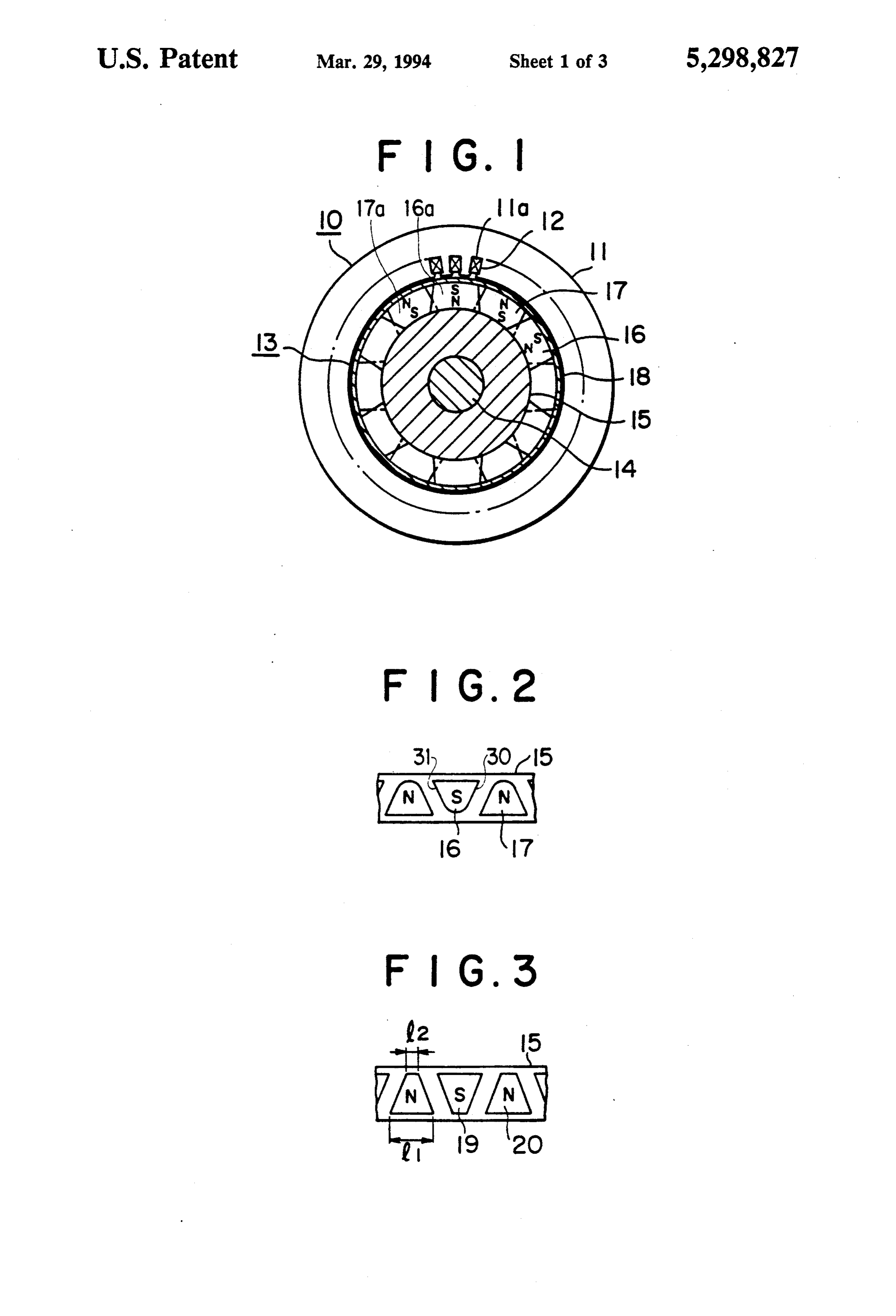
ent magnetic flux densities, i.e., an increased magnetiza FIG. 1 is a cross-sectional view of a dynamoelectric tion portion and a decreased magnetization portion machine rotor of one embodiment of the present inven appear due to the armature reaction by the energized tion;
stator windings, so that the output power is disadvanta FIG. 2 is an extended view of the permanent magnets geously decreased. 50 illustrating the arrangement of the permanent magnets on the outer circumference of the magnetic yoke;
SUMMARY OF THE INVENTION FIG. 3 is an extended view of the permanent magnets Accordingly, one object of the present invention is to illustrating the arrangement of the permanent magnets provide a dynamoelectric machine rotor free from the on the outer circumference of the magnetic yoke; above-discussed drawbacks of the conventional dyna 55 FIG. 4 is a graph illustrating how the proportion of moelectric machine rotor.
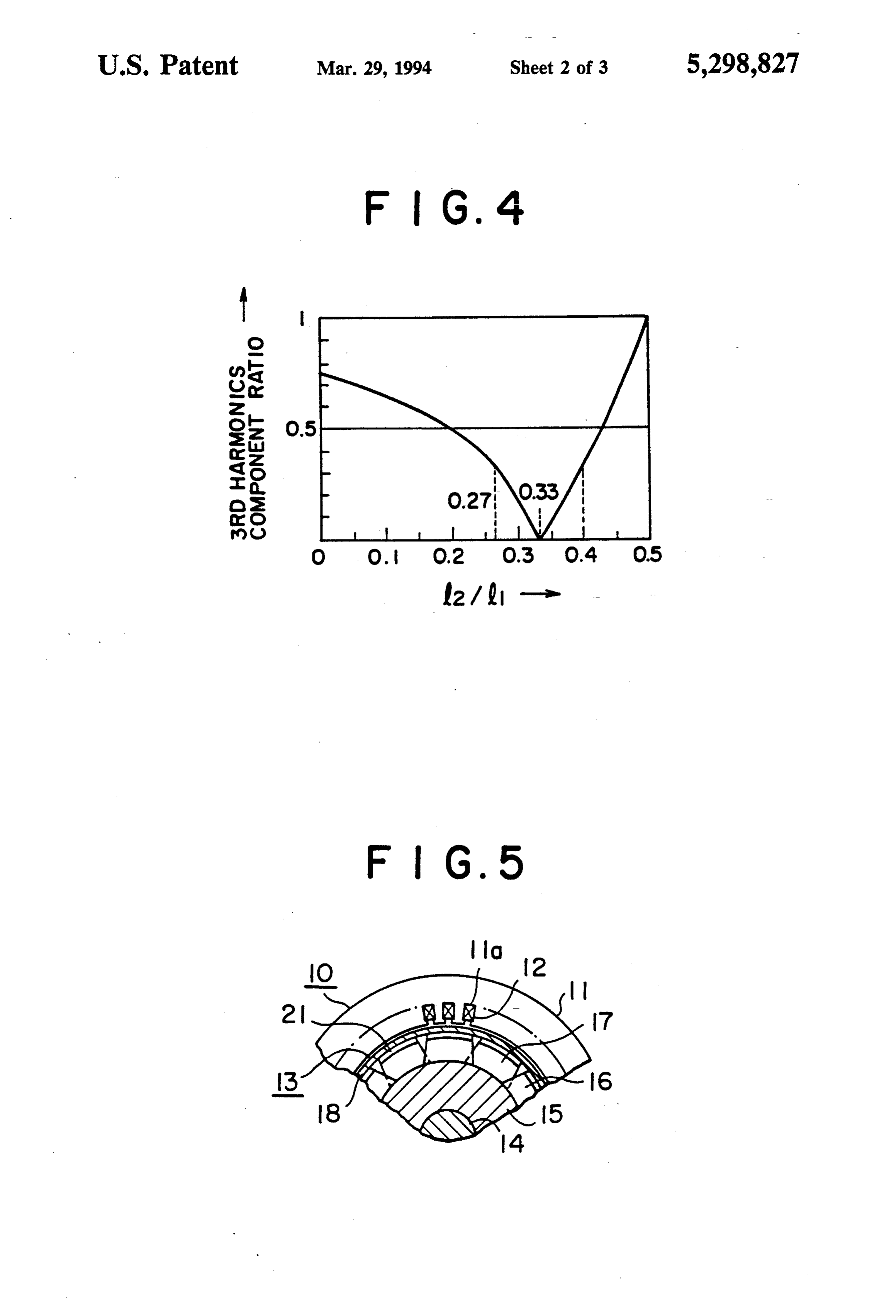
Another object of the present invention is to provide the the third harmonic component changes as the ratio of shorter side to the longer side changes;
a dynamoelectric machine rotor in which the output FIG. 5 is a fragmental cross-sectional view of a dyna torque change and the magnetic noise are decreased. moelectric machine rotor of another embodiment of the Another object of the present invention is to provide a dynamoelectric machine rotor in which the output present invention;
FIG. 6 is a fragmental cross-sectional view of a dyna power is increased and the demagnetization is de moelectric machine rotor of a further embodiment of creased.
With the above objects in view, the present invention theFIG. present invention;
7 is an extended view of the permanent magnets resides in a dynamoelectric machine rotor which com 65 prises a rotary shaft having a central axis, a magnetic illustrating the arrangement of the permanent magnets yoke mounted on the rotary shaft for rotation there on the outer circumference of the magnetic yoke of with, and a clamp ring disposed around the magnetic FIG. 6;
Page 6
FIG. 8 is a fragmental cross-sectional view of a dyna ential surface of the magnetic yoke 15 with the mag moelectric machine rotor of a still another embodiment netic pole faces 16a and 17a are lying in a circumferen of the present invention; tial plane directly facing toward the air gap defined FIG. 9 is an extended view of the permanent magnets between the stator 10 and the rotor 13 and since the illustrating the arrangement of the permanent magnets magnetic flux entering into the stator core 11 is a section on the outer circumference of the magnetic yoke of of a predetermined sine wave. Therefore, a smooth FIG. 8; rotating torque can be obtained when the rotor is ap FIG. 10 is a fragmental cross-sectional view of a plied to an electric motor and the generation of mag dynamoelectric machine of another embodiment; and netic noise is prevented when the rotor is applied to a FIG. 11 is a side view of the rotor of the conventional 10 generator.
design. FIG. 3 illustrates a modification of the trapezoidal
DESCRIPTION OF THE PREFERRED
cross section of a permanent magnets 19 and 20 which
EMBODIMENTS
has a shorter side having a length l of from 27 to 40 percent of a length 11 of a longer side. Preferably, the
FIG. 1 illustrates an alternating current generator 15 length lis about 33 percent of the length 11. It is seen in comprising a hollow stator 10 and a permanent magnet this example that the corners defined between the sides field magnet type rotor 13 of the present invention. The are not rounded. In other respects, the arrangement is rotor 13 is rotatably disposed within the stator 10 which similar to those illustrated and described in conjunction comprises a stator windings 12 inserted into slots 11a of with FIGS. 1 and 2. It is generally known that, when a the stator iron core 11. 20 three-phase a.c. voltage is supplied to a stator windings, The rotor 13 comprises a rotary shaft 14, a substan what is to be reduced is the third harmonic component tially drum-shaped magnetic yoke 15 concentrically of the intersecting magnetic flux. As clearly seen from mounted on the rotary shaft 14 for rotation therewith, a the graph of FIG. 4 which illustrates the third harmonic plurality of permanent magnets 16 and 17 mounted on component ratio, which is illustrated as 1 when l is 0.5, the magnetic yoke 15 at a substantially equal radial 25 as plotted against the change in the ratio of the shorter dimension and substantially equal circumferential inter side length 12 relative to the longer side length ll, the vals with respect to the rotary shaft 14, and a clamp ring third harmonic component of the intersecting magnetic 18 disposed around the permanent magnets 16 and 17 flux becomes small when the l/l is between 0.27 and for mechanically rigidly maintaining them on the mag 0.4 and the similar advantageous results as in the case netic yoke 15. 30 where the sine wave-shaped magnets are used can be Each of the permanent magnets 16 and 17 is a sub obtained.
stantially prism-shaped member and has a substantially FIG. 5 illustrates another embodiment of the dyna trapezoidal cross section rounded at its corners defined moelectric machine rotor of the present invention in by shorter sides of the trapezoid as best shown in FIG. which the rotor 13 further comprises a ferromagnetic 2. The opposite ends of the permanent magnets 16 and 35 material 21 attached between the outer magnetic pole 17 define magnetic pole faces 16a and 17a which lie in faces 16a and 17a of each of the permanent magnets 16 an imaginary circumferential cylindrical plane concen and 17 and the clamp ring 18. The ferromagnetic mate tric to the outer circumferential surface of the drum rial 21 may be made of a high magnetic permeability shaped magnetic yoke 15, and the magnetic pole faces soft iron. In this arrangement, since the magnetic flux 16a and 17a of the permanent magnets 16 and 17 have generated by the stator windings 12 passes through the opposite magnetic polarities N and S which appear ferromagnetic material 21 and not through the perma alternatively in the circumferential direction. In the nent magnets 16 and 17, the reduction of the magnetiza illustrated embodiment, the magnetic pole faces 16a of tion of the permanent magnets 16 and 17 can be pre the permanent magnets 16 are in the S polarity at its vented under the circumstances in which the armature radially outer ends, and the magnetic pole faces 17a of 45 reaction is very high. Also, by increasing the magnetic the permanent magnets 17 disposed between the mag flux amount within the air gap, the output power can be nets 16 are in the N polarity at its radially outer ends. increased.
Thus, the permanent magnets 16 and 17 mounted on the FIGS. 6 and 7 illustrates another embodiment of the outer circumferential surface of the magnetic yoke 15 present invention in which the dynamoelectric machine provide a magnetic field of an alternative magnetic 50 rotor for use in a generator comprises a ferromagnetic polarity in the circumferential direction. Side surfaces material 22 attached to each of the permanent magnets of the permanent magnets 16 and 17 are in a plane per 16 and 17 on a rear skewed side surfaces for allowing a pendicular to the rotational axis of the rotary shaft 14. magnetic flux from a stator to cause the increase of the The permanent magnets 16 and 17 have a front skewed magnetization of the permanent magnets 16 and 17. The surface 30 and a rear skewed surface 31 generally 55 side surfaces of the permanent magnets 16 and 17 are slanted in different direction with respect to a plane rear side surfaces in the sense that they are rear side as parallel to the axis of rotation of the rotary shaft 14, and viewed in the direction of rotation of the rotor indicated the front and rear skewed surfaces 30 and 31 of the by an arrow A.
neighboring permanent magnets 16 and 17 are disposed FIGS. 8 and 9 illustrate another embodiment of the in parallel to each other. present invention in which the dynamoelectric machine In other words, the permanent magnets 16 and 17 are rotor comprises a ferromagnetic material 22 attached to circumferentially alternatingly mounted on the outer each of the permanent magnets 16 and 17 on a front periphery of the magnetic yoke 15 so that not only their skewed side surfaces for allowing a magnetic flux from magnetic polarity is alternative but also their rounded a stator to cause the increase of the magnetization of the shorter side and the rounded longer side of the trapezoi 65 permanent magnets 16 and 17. The ferromagnetic mate dal cross section are alternative. rials 22 are attached to the sides of the magnets 16 and With the above construction, since the permanent 17 which are front side as viewed in the direction of magnets 16 and 17 are mounted on the outer circumfer rotation of the rotor shown by the arrow A.
Page 7
In these embodiments, the ferromagnetic materials 22 substantially prism-shaped and has a substantially trape are attached to the rear or front side surfaces of the zoidal cross section rounded at it corners of the shorter permanent magnets 16 and 17 or 19 and 20, so that the sides of the trapezoid.
magnetic fluxes extending from the stator coils 12 are 4. A dynamoelectric machine rotor as claimed in forced to pass through these ferromagnetic materials 22, claim 1, further comprising a ferromagnetic material whereby the reduction of the magnetization of the per attached between said magnetic pole faces of said per manent magnets 16 and 17 or 19 and 20 can be pre manent magnets and said clamp ring. vented and the output power can be increased. 5. A dynamoelectric machine rotor as claimed in FIG. 10 illustrates a further embodiment of the dyna claim 1, further comprising a ferromagnetic material moelectric machine rotor of the present invention 10 attached to each of said permanent magnets on at least which comprising a slit 23 formed in the magnetic yoke a front and a rear skewed side surfaces for allowing a 15 at a portion to which the respective permanent mag magnetic flux from a stator to cause the increasing of nets 16 and 17 are mounted for increasing a magnetic the magnetization of said permanent magnets. reluctance of a magnetic circuit passing through a com 6. A dynamoelectric machine rotor as claimed in mon permanent magnets 16 and 17. More particularly, 15 claim 1, further comprising a slit formed in said mag the slit 23 is radially and axially extending from the netic yoke at a portion to which said permanent mag outer circumferential surface of the magnetic yoke 15 nets are mounted for increasing a magnetic reluctance and positioned at the center of each of the permanent of a magnetic circuit passing through a common perma magnets 16 or 17. With this arrangement, the magnetic nent magnet.
flux d generated by the permanent magnets 16 and 17 is 20 7. A dynamoelectric machine rotor comprising: allowed to freely pass through the magnetic circuit a rotary shaft having a central axis; while the magnetic flux d 1 generated by the stator a magnetic yoke mounted on said rotary shaft for windings 12 and otherwise flows through into the rotor rotation therewith;
13 is prevented by the magnetic reluctance of the slits a plurality of substantially trapezoidal prism-shaped 23, whereby the armature reaction can be decreased. If 25 permanent magnets mounted on said magnetic desired, the slits 23 may be filled with a non-magnetic yoke at a substantially equal radial dimension and material. substantially equal circumferential intervals with What is claimed is: respect to said central axis of said rotary shaft, each 1. A dynamoelectric machine rotor comprising: of said permanent magnets having magnetic pole a rotary shaft having a central axis; 30 faces in a circumferential plane, side surfaces in a a magnetic yoke mounted on said rotary shaft for plane perpendicular to said central axis of said rotation therewith; rotary shaft and a front and a rear skewed surface a plurality of permanent magnets mounted on said generally slanted in a direction which does not lie magnetic yoke at a substantially equal radial dimen on a plane parallel to said central axis, said mag sion and substantially equal circumferential inter 35 netic pole faces of said permanent magnets having vals with respect to said central axis of said rotary alternating magnetic polarities in a circumferential shaft, each of said permanent magnets having mag direction, and said front and rear skewed surfaces netic pole faces in a circumferential plane, side of neighboring permanent magnets of said perma surfaces in a plane perpendicular to said central nent magnets are substantially in parallel to each axis of said rotary shaft and a front and a rear 40 skewed surface generally slanted in a direction other;
which does not lie in a plane parallel to said central each of said permanent magnets having a trapezoidal axis, said magnetic pole faces of said permanent cross section, said trapezoidal cross section having magnets having alternating magnetic polarities in a a short side and a long side, a length of said shorter circumferential direction, and said front and rear 45 side being from 27 to 40 percent of a length of said skewed surfaces of neighboring permanent mag longer side;
nets of said permanent magnets are substantially in a clamp ring disposed around said magnetic pole parallel to each other; and faces of said permanent magnets for mechanically each of said permanent magnets having a trapezoidal maintaining said permanent magnets on said mag cross section, said trapezoidal cross section having 50 netic yoke;
a short side and a long side, a length of said shorter a ferromagnetic end material attached between each side being from 27 to 40 percent of a length of said of said magnetic pole faces of said permanent mag longer side; nets and said clamp ring;
a clamp ring disposed around said magnetic pole a ferromagnetic side material attached to each of said faces of said permanent magnets for mechanically 55 permanent magnets on at least a front and a rear maintaining said permanent magnets on said mag skewed side surface for allowing a magnetic flux netic yoke. from a stator to cause an increase in magnetization 2. A dynamoelectric machine rotor as claimed in of said permanent magnets; and claim 1, wherein each of said permanent magnets is a slit formed in said magnetic yoke at a portion to substantially prism-shaped and has a substantially trape 60 which said permanent magnets are mounted for zoidal cross section. increasing a magnetic reluctance of a magnetic 3. A dynamoelectric machine rotor as claimed in circuit passing through sk six k saidis permanent six magnets.
claim 1, wherein each of said permanent magnets is
Provenance
- Collection
- Cited prior art
- Original PDF
- patentimages.storage.googleapis.com →
- Filed
- 1992-11-25
- Pages
- 7
- Method
- pdftotext (the PDF's own text layer) + pdftoppm 300dpi page scans
- Source
- Google Patents bibliographic record
- Granted
- 1994-03-29
- Inventors
- Takeshi Sugiyama; Mitsubishi Electric Corp
- Transcribed from
- patentimages.storage.googleapis.com →