patent · US5456579
Wind turbine blade with governor for maintaining optimum rotational speeds
10 October 1995
Page 1 — bibliographic record
United States Patent (19) 11) Patent Number: 5,456,579 Olson 45 Date of Patent: Oct. 10, 1995 (54) WIND TURBINE BLADE WITH GOVERNOR 4,123,198 10/1978 Harbord .............................. 4161223 R FOR MANTAINING OPTIMUM 4,565,929 1/1986 Baskin et al. ......... ... 416/23 ROTATIONAL SPEEDS 4,692,095 971987 Lawson-Tancred ... ... 416/23 4,718,821 1/1988 Clancy ...................................... 46/44 76 Inventor: Timothy G. Olson, 21200 Quail Primary Examiner-Edward K. Look
Springs Rd., Tehachapi, Calif. 93561 Assistant Examiner Christopher Verdier 21 Appl. No.: 251,321 (57) ABSTRACT 22 Filed: May 31, 1994 A wind turbine blade with governor for maintaining opti mum rotational speeds comprising, in combination: a main (51 int. Cl. ........................ FO3D 7/04 body portion with a linear leading edge and a trailing edge, 52 U.S. Cl. .......................... 416/23; 416/51; 416/DIG. 7 a trailing edge, a tip end and an axis end, the leading edge 58 Field of Search .................................. 416/23, 24, 44, being linear and fixed and the trailing edge being formed at 416/44 A, 51, 51 A, 52, 52A, DIG. 7, an angle with respect to the leading edge over the majority 223R; 244/213, 215 of its central extent, the trailing edge being formed with a rectangular recess; and an aileron formed within the recess 56 References Cited of the trailing edge of the main body portion with a pivot pin extending through a central extent thereof, the aileron
2,372,030 3/1945 Stalker ...................................... 41624 edges of the recess for rotation thereof about an axis parallel 2,625,997 1/1953 Doak ...... ... 46/23 with the trailing edge of the main body portion. 2,716,460 8/1955 Young ... ... 416/24 2,776,718 1/1957 Zuck ......................................... 416/23 2 Claims, 4 Drawing Sheets
Page 2
Drawing sheet — no readable text.
Page 3
Drawing sheet — no readable text.
Page 4
Drawing sheet — no readable text.
Page 5
Drawing sheet — no readable text.
Page 6
WNDTURBINE BLADE WITH GOVERNOR a wind turbine blade with governor for maintaining optimum FOR MANTAINING OPTIMUM rotational speeds comprising, in combination: a main body ROTATIONAL SPEEDS portion with a leading edge, a trailing edge, a tip end and an axis end, the leading edge being linear and fixed and the trailing edge being formed at an angle with respect to the
BACKGROUND OF THE INVENTION leading edge over the majority of its central extent, the trailing edge being formed with a rectangular recess; an 1. Field of the Invention aileron formed within the recess of the trailing edge of the The present invention relates to a wind turbine blade with main body portion with a pivot pin extending through a governor for maintaining optimum rotational speeds and 10 portioncentral extent thereof, the aileron coupled to the main body more particularly pertains to maintaining the optimum adjacent to the opposed edges of the recess for speeds for wind turbine blades through the use of a governor rotation thereof about an axis parallel with the trailing edge of the main body portion; and control mechanisms for to vary the aileron positioning as a function of wind speed. varying the angular orientation of the aileron as a function 2. Description of the Prior Art of wind speed, the control mechanisms including a rod 15 located adjacent to the tip end of the main body portion with
The use of wind turbine blades of various designs is its axis parallel with the leading edge of the main body known in the prior art. More specifically, wind turbine blades of various designs heretofore devised and utilized for portion, a coil spring located around the rod and a lead weight at the inboard edge of the spring whereby increased the purpose of varying the operational characteristics of wind turbine blades and their ailerons through a wide variety 20 rotational speeds of the main body portion will cause the of mechanisms are known to consist basically of familiar, outboard movement of the weight under the action of the expected, and obvious structural configurations, notwith centrifugal force generated by the rotating main body por standing the myriad of designs encompassed by the crowded tion, a linkage member adapted for rotation about an axis prior art which has been developed for the fulfillment of perpendicular to the axis of the red located at a central extent countless objectives and requirements. of the main body portion, the linkage member having a 25 leading end secured to the inboard end of the rod and a
By way of example, the prior art discloses in U.S. Pat. No. trailing end, the trailing end secured to a short rod coupled 5,226,805 to Proven a windmill having blades which alter their pitch angles automatically in response to both wind to the aileron remote from its pivot pin whereby rotational movement of the linkage member in response to rotation of speed and load. the main body portion will cause rotation of the aileron to a U.S. Pat. No. 5,159,620 to Bordelon discloses a variable 30 full drag position upon excess winds causing excess move pitch propeller apparatus. ment of the weight outboardly while minimum and no U.S. Pat. No. 5,5028,209 to Wantonen discloses a wind rotational forces on the link will cause the aileron to be in the power plant construction. Zero tether orientation.
U.S. Pat. No. 4,720,062 to Warrink discloses an aileron 35
There has thus been outlined, rather broadly, the more for an airplane wing. important features of the invention in order that the detailed U.S. Pat. No. 4,029.434 to Kenney discloses a variable description thereof that follows may be better understood pitch mounting for airfoil blades of a windmill or propeller. and in order that the present contribution to the art may be In this respect, the wind turbine blade with governor for better appreciated. There are, of course, additional features maintaining optimum rotational speeds according to the 40 of the invention that will be described hereinafter and which present invention substantially departs from the conven will form the subject matter of the claims appended hereto. tional concepts and designs of the prior art, and in doing so In this respect, before explaining at least one embodiment provides an apparatus primarily developed for the purpose of the invention in detail, it is to be understood that the of maintaining the optimum speeds for wind turbine blades invention is not limited in its application to the details of through the use of a governor to vary the aileron positioning 45 construction and to the arrangements of the components set as a function of wind speed. forth in the following description or illustrated in the draw Therefore, it can be appreciated that there exists a con ings. The invention is capable of other embodiments and of tinuing need for a new and improved wind turbine blade being practiced and carried out in various ways. Also, it is with governor for maintaining optimum rotational speeds to be understood that the phraseology and terminology which can be used for maintaining the optimum speeds for 50 employed herein are for the purpose of descriptions and wind turbine blades through the use of a governor to vary the should not be regarded as limiting. aileron positioning as a function of wind speed. In this As such, those skilled in the art will appreciate that the regard, the present invention substantially fulfills this need. conception, upon which this disclosure is based, may readily be utilized as a basis for the designing of other structures,
SUMMARY OF THE INVENTION 55 methods and systems for carrying out the several purposes of the present invention. It is important, therefore, that the
In view of the foregoing disadvantages inherent in the claims be regarded as including such equivalent construc known types of wind turbine blades of various designs now tions insofar as they do not depart from the spirit and scope present in the prior art, the present invention provides an of the present invention.
improved wind turbine blade with governor for maintaining 60 Further, the purpose of the foregoing abstract is to enable optimum rotational speeds. As such, the general purpose of the U.S. Patent and Trademark Office and the public gen the present invention, which will be described subsequently erally, and especially the scientists, engineers and practitio in greater detail, is to provide a new and improved wind ners in the art who are not familiar with patent legal terms turbine blade with governor for maintaining optimum rota or phraseology, to determine quickly from a cursory inspec tional speeds and method which has all the advantages of the 65 tion the nature and essence of the technical disclosure of the prior art and none of the disadvantages. application. The abstract is neither intended to define the To attain this, the present invention essentially comprises invention of the application, which is measured by the
Page 7
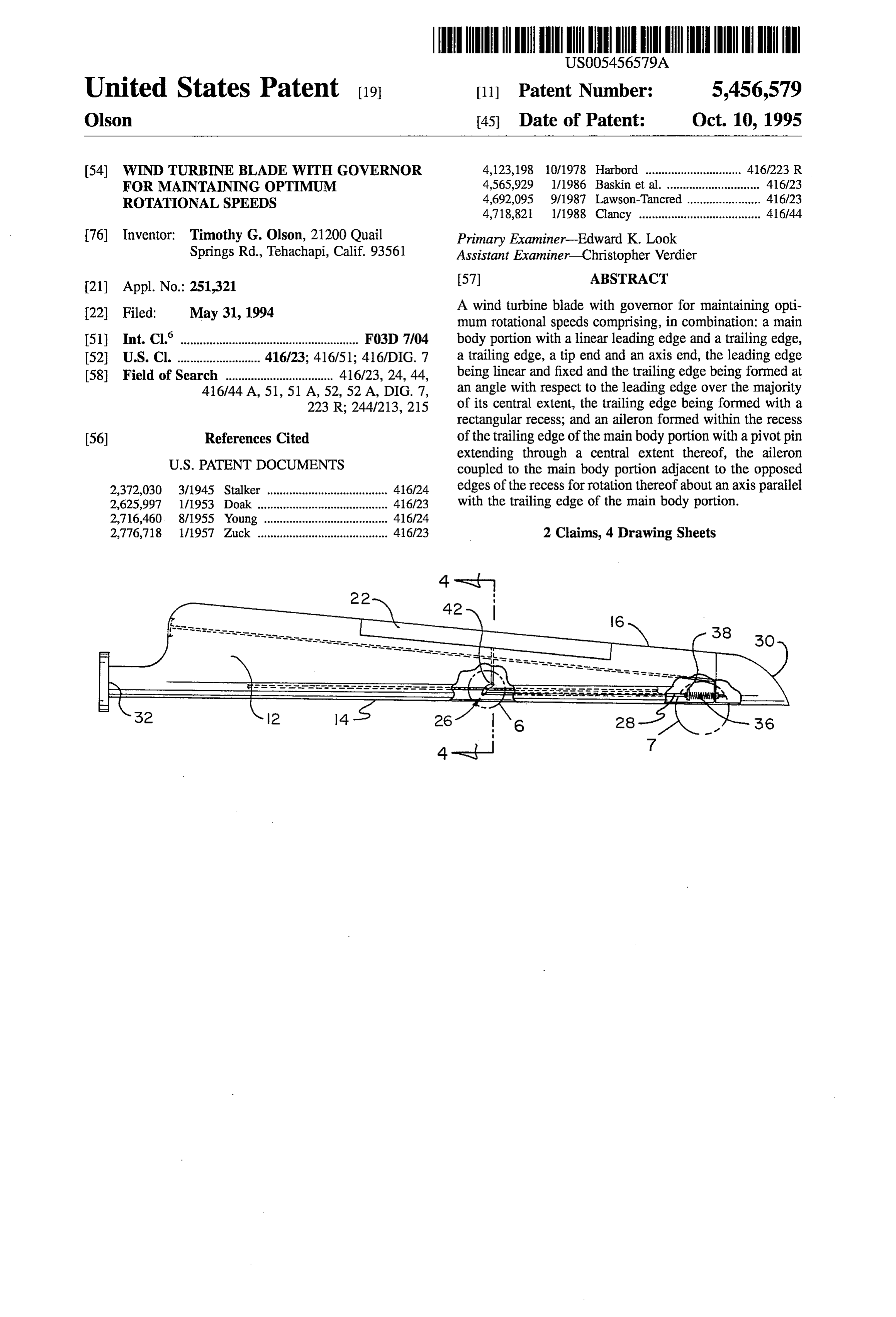
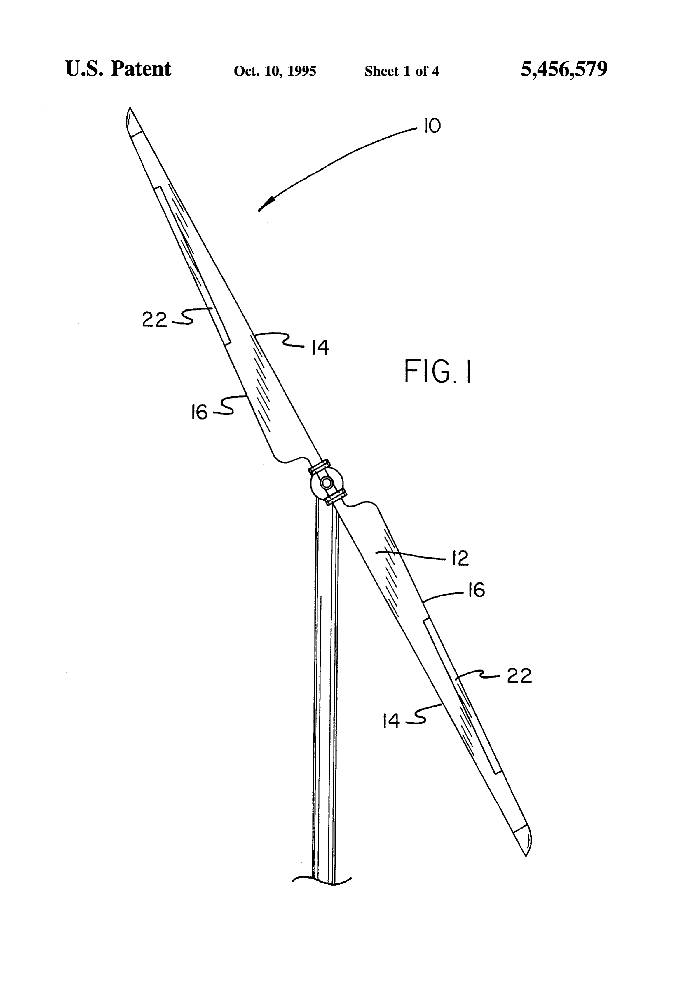
claims, nor is it intended to be limiting as to the scope of the FIG. 1 is a front elevational view of a pair of wind turbine invention in any way. blades constructed in accordance with the principles of the It is therefore an object of the present invention to provide present invention.
a new and improved wind turbine blade with governor for FIG. 2 is an enlarged front elevational view of one of the maintaining optimum rotational speeds which have all the blades illustrated in FEG, 1.
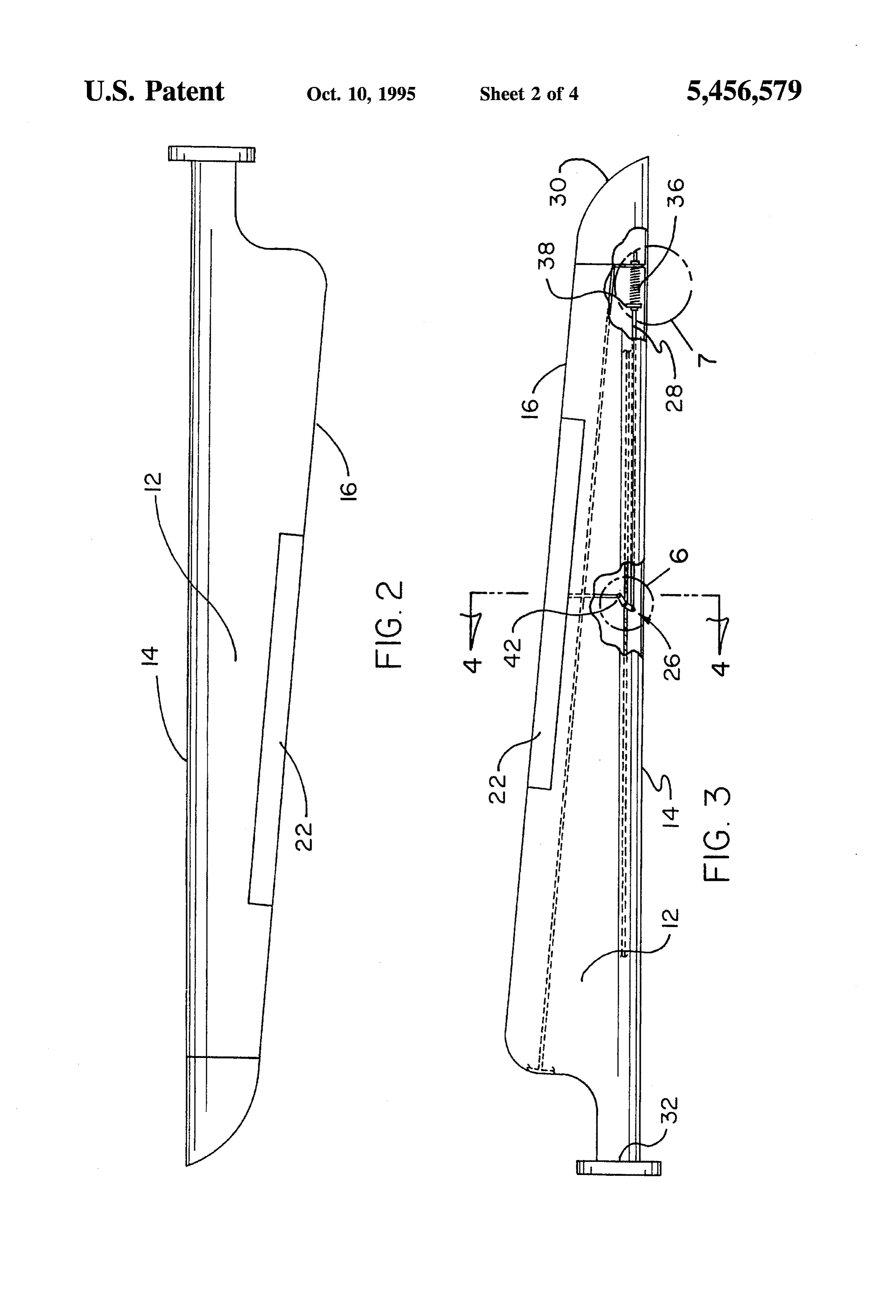
advantages of the prior art wind turbine blades of various FIG. 3 is a view of a wind turbine blade similar to that of designs and none of the disadvantages. FIG. 2 but with parts broken away to show certain internal It is another object of the present invention to provide a construction thereof.
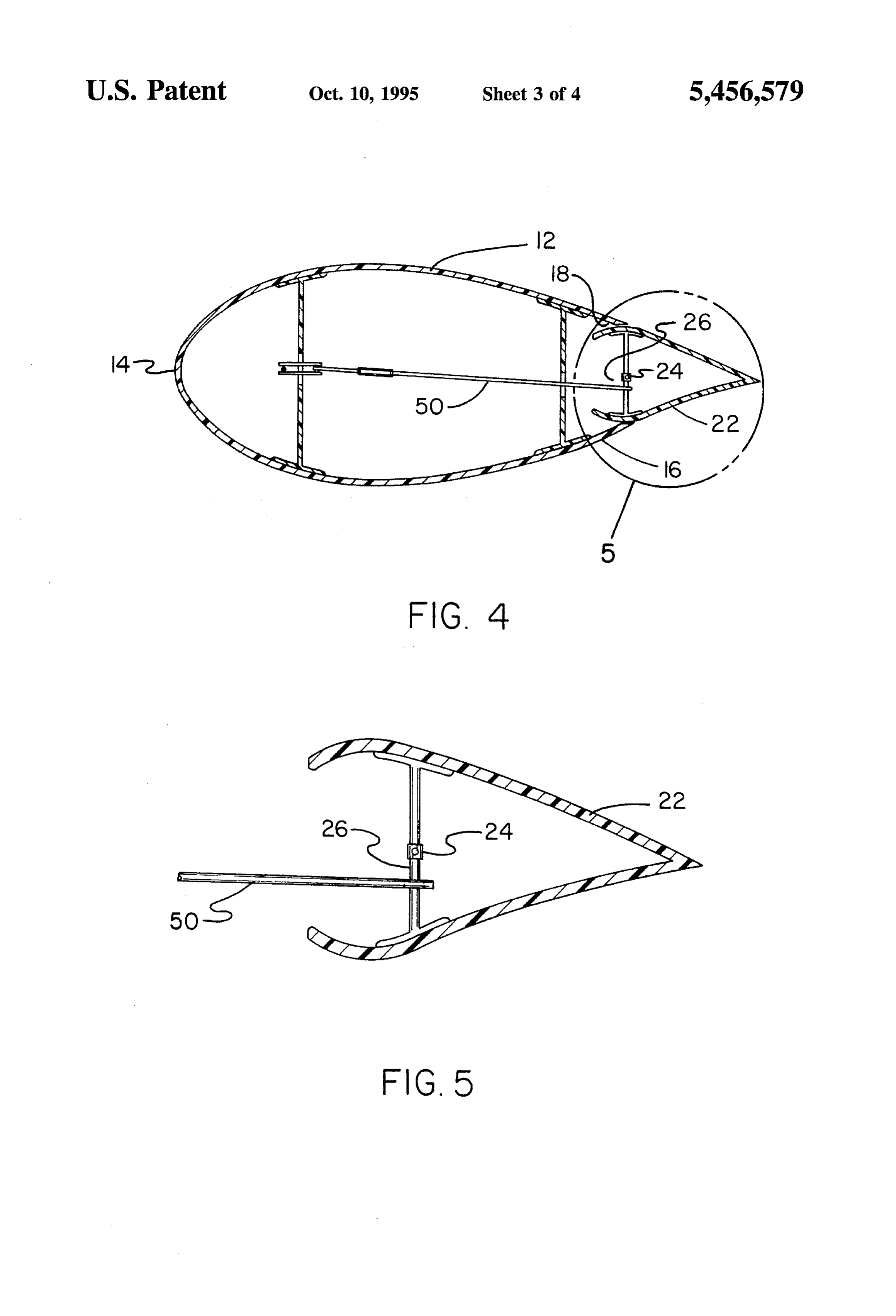
new and improved wind turbine blade with governor for O FIG. 4 is a cross sectional view of the wind turbine blade maintaining optimum rotational speeds which may be easily shown in FIG. 3 taken along line 4-4 of FIG. 3. and efficiently manufactured and marketed. FIG. 5 is an enlarged view of the aileron illustrated in FIG. It is further object of the present invention to provide a 4 taken about circle 5 of FIG. 4.
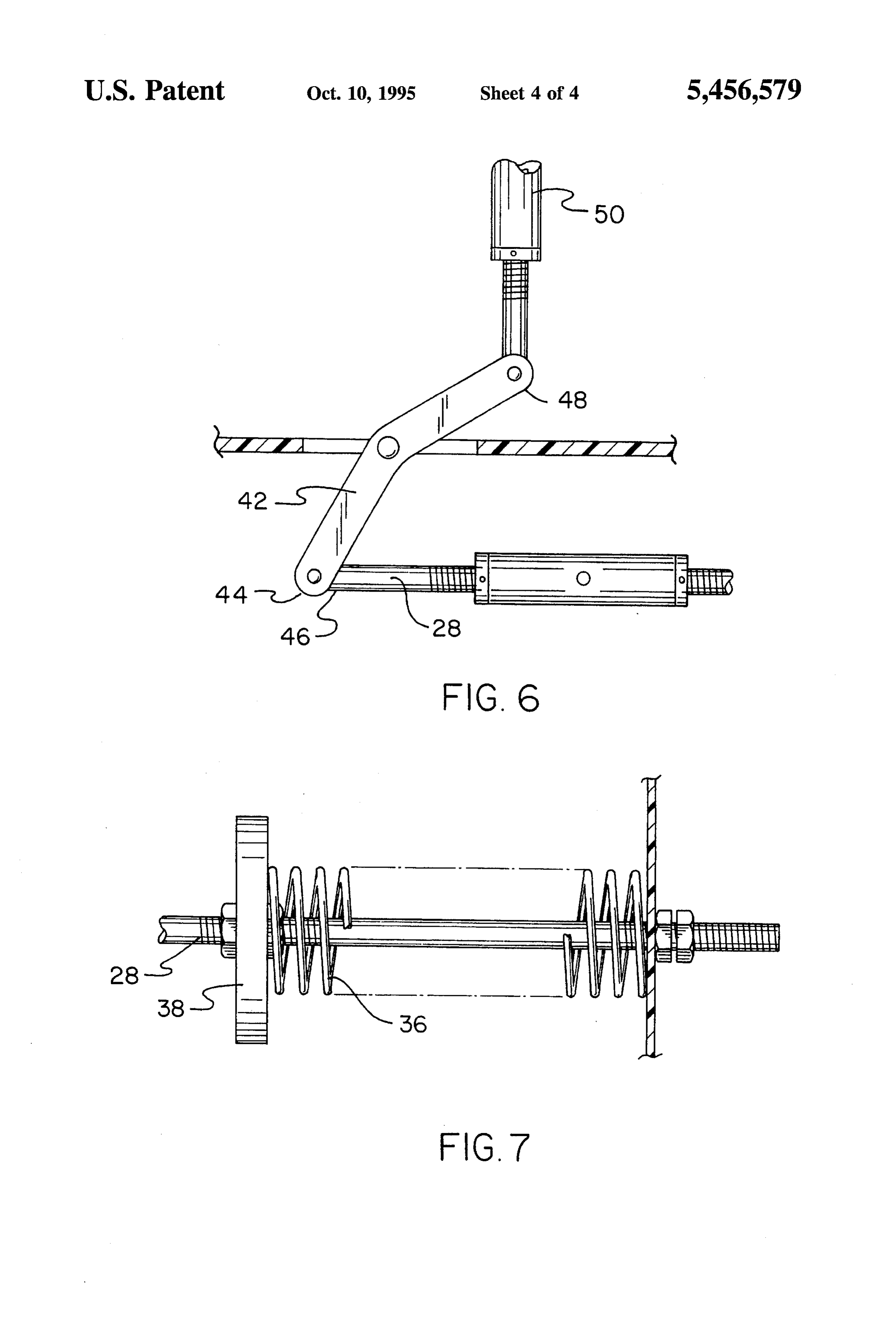
new and improved wind turbine blade with governor for FIG. 6 is an enlarged view of a central portion of the wind maintaining optimum rotational speeds which are of durable 15 turbine blade shown in FIG. 3 taken about 6 of FIG. 3. and reliable constructions.
An even further object of the present invention is to FIG. 7 is an enlarged illustration of a portion of the wind provide a new and improved wind turbine blade with turbine blade shown in the previous Figures taken about circle 7 of FIG. 3.
governor for maintaining optimum rotational speeds which are susceptible of a low cost of manufacture with regard to 20 through The same reference numerals refer to the same parts both materials and labor, and which accordingly are then the various Figures.
susceptible of low prices of sale to the consuming public, thereby making such wind turbine blade with governor for DESCRIPTION OF THE PREFERRED maintaining optimum rotational speeds economically avail EMBODIMENT able to the buying public. 25 With reference now to the drawings, and in particular to Still yet another object of the present invention is to FIG. 1 thereof, the preferred embodiment of the new and provide a new and improved wind turbine blade with improved wind turbine blade with governor for maintaining governor for maintaining optimum rotational speeds which optimum rotational speeds embodying the principles and provide in the apparatuses and methods of the prior art some concepts of the present invention and generally designated of the advantages thereof, while simultaneously overcoming 30 by the reference numeral 10 will be described. some of the disadvantages normally associated therewith. The invention, the new and improved wind turbine blade Still another object of the present invention is to maintain with governor for maintaining optimum rotational speeds is the optimum speeds for wind turbine blades through the use comprised of a plurality of components. In their broadest of a governor to vary the aileron positioning as a function of context, such components include an aileron and control wind speed. 35 mechanisms. Such components are specifically configured
Lastly, it is an object of the present invention to provide and correlated with respect to each other so as to attain the a new and improved wind turbine blade with governor for desired objective.
maintaining optimum rotational speeds comprising, in com More specifically, the system 10 of the present invention bination: a main body portion with a linear leading edge and 40 includes a main body portion 12. Such main body portion a trailing edge, a trailing edge, a tip end and an axis end, the has a leading edge 14. The leading edge is linear and fixed. leading edge being linear and fixed and the trailing edge The main body portion also has a trailing edge 16. Thc being formed at an angle with respect to the leading edge trailing edge is formed at an angle with respect to the leading over the majority of its central extent, the trailing edge being edge over the majority of its central extent. The trailing edge formed with a rectangular recess; and an aileron formed 45 is formed with a rectangular recess 18.
within the recess of the trailing edge of the main body The next component of the system is an aileron 22. The portion with a pivot pin extending through a central extent aileron is formed within the recess of the trailing edge of the thereof, the aileron coupled to the main body portion adja main body portion. It has a pivot pin 24 extending through cent to the opposed edges of the recess for rotation thereof a central extent thereof. The aileron is coupled to the main about an axis parallel with the trailing edge of the main body 50 body portion adjacent to the opposed edges of the recess. portion. This is for rotation of the aileron about an axis parallel with These together with other objects of the invention, along the trailing edge of the main body portion. Next provided are with the various features of novelty which characterize the the control mechanisms 26 for movement of the aileron with invention, are pointed out with particularity in the claims respect to the main body portion. The control mechanisms annexed to and forming a part of this disclosure. For a better 55 function through varying the angular orientation of the understanding of the invention, its operating advantages and aileron as a function of the wind speed. More specifically, the specific objects attained by its uses, reference should be the control mechanisms include a rigid rod 28. Such rigid had to the accompanying drawings and descriptive matter in rod is located adjacent to the tip end 30 of the main body which there is illustrated preferred embodiments of the portion. The tip end is opposite from the axis end 32 of the invention. 60 main body portion. The axis of the rod is parallel with the
BRIEF DESCRIPTION OF THE DRAWINGS
leading edge of the main body portion.
In association with the rod, a coil spring 36 is located
The invention will be better understood and objects other around the rod adjacent to the tip end. Inboardly of the tip than those set forth above will become apparent when end and spring is a heavy weight 38. Such heavy weight is consideration is given to the following detailed description 65 preferably made of lead. It is located at the inboard edge of thereof. Such description makes reference to the annexed the spring and coupled thereto whereby increased rotation of drawings wherein: speeds of the main body portion will cause the weight to
Page 8
S 6 move outboardly under the action of centrifugal force as be resorted to, falling within the scope of the invention. generated by the rotation of the main body portion. What is claimed as being new and desired to be protected A linkage member 42 is adapted for rotation about an axis by Letters Patent of the United States is as follows: perpendicular to the axis of the rod. The linkage member is 1. A new and improved wind turbine blade with governing located at a central extent of the main body portion. Such 5 capabilities for maintaining optimum rotational speeds com linkage member has a leading end 44 secured to the inboard prising, in combination:
end 46 of the rod. The linkage also has a trailing end 48. The a main body portion with a leading edge, a trailing edge, trailing end is secured to a short rod 50. The short rod is a tip end and an axis end with a central extent ther coupled to the aileron at a location remote from its pivot pin. ebetween, the leading edge being linear and fixed and In this manner, rotational movement of the linkage member 10 the trailing edge being formed at an angle with respect in response to rotation of the main body portion will cause to the leading edge over the majority of its central rotation of the aileron. Such rotation will be to a full drag extent, the trailing edge being formed with a rectangu position upon excess winds causing excess movement of the lar recess with opposed edges; weight outboardly. Conversly, minimum or no rotational forces on the link will cause the aileron to be in a zero tether 15 an aileron formed within the recess of the trailing edge of orientation as shown in FIG. 4. the main body portion with a pivot pin extending The present invention is a cost effective wind turbine through a central extent thereof, the aileron coupled to the main body portion adjacent to the opposed edges of blade that is capable of generating more power on a rela the recess for rotation thereof about an axis parallel tively low wind speed day. A lot of wind turbines currently with the trailing edge of the main body portion; and in use don't produce optimum power output on these days. 20
Another problem is the use of materials that are prone to tip control mechanisms for varying the angular orientation of breakage in the manufacture of the blades. To replace the the aileron as a function of wind speed, the control blade and get the turbine back on line can take as long as mechanisms including a rod having an inboard end and three hours and can be costly in lost time, power and spare an outboard end located adjacent to the tip end of the parts. The present invention solves these problems. 25 main body portion with its axis parallel with the leading edge of the main body portion, a coil spring with an
The innovative blade design utilizes a single aileron inboard edge and an outboard edge located around the operated by a centrifugal force mechanism. It features a high rod and a lead weight at the inboard edge of the spring strength Kevlar outer skin and a core of high density whereby increased rotational speeds of the main body Rohacell, which is backed up by a unidirectional fiberglass portion will cause movement of the weight toward the layup. The interstringers are made with Kevlar that is would 30 tip end when centrifugal force is generated by the with carbon fibers for increased flexibility and strength. rotation of the main body portion, a linkage member The key to the improved operation of this system is the adapted for rotation about an axis perpendicular to the lead weight governor installed at its tip. The weight is axis of the rod located at a central extent of the main mounted on a push-pull rod along with a tension spring and body portion, the linkage member having a leading end a nut for adjusting the spring and weight. The rod is also 35 secured to the inboard end of the rod and a trailing end, connected to a bell crank that adjust the position of the the trailing end secured to a supplemental rod coupled aileron. to the aileron remote from its pivot pin whereby The aileron is set to rest in full lift position by setting a rotational movement of the linkage member in response predetermined tension on the lead weight-spring assembly 40 to rotation of the main body portion will cause rotation with the adjusting nut. As the turbine rotates faster, centrifu of the aileron to a full drag position upon excess winds gal force pushes the lead weight out, thereby compressing causing excess movement of the weight outboardly the tension spring and pulling on the rod and bell crank. This while minimum and no rotational forces on the link will moves the aileron to a lower lift position, thus slowing down cause the aileron to be in an orientation for Zero tether. the turbine. With the velocity reduced, the spring returns the 45 2. A wind turbine blade with governing capabilities for weight to its original position, thereby adjusting the aileron maintaining optimum rotational speeds comprising, in com as well. There is no need for the turbine to stop. The present bination:
invention could be available for both new and already a main body portion with a linear leading edge and a existing systems. trailing edge with a central extent therebetween, a tip As to the manner of usage and operation of the present 50 end and an axis end, the leading edge being linear and invention, the same should be apparent from the above fixed and the trailing edge being formed at an angle description. Accordingly, no further discussion relating to with respect to the leading edge over the majority of its the manner of usage and operation will be provided. central extent, the trailing edge being formed with a With respect to the above description then, it is to be rectangular recess with opposed edges; realized that the optimum dimensional relationships for the 55 an aileron formed within the recess of the trailing edge of parts of the invention, to include variations in size, materials, the main body portion with a pivot pin extending shape, form, function and manner of operation, assembly through a central extent thereof, the aileron coupled to and use, are deemed readily apparent and obvious to one the main body portion adjacent to the opposed edges of skilled in the art, and all equivalent relationships to those the recess for rotation thereof about an axis parallel illustrated in the drawings and described in the specification 60 with the trailing edge of the main body portion; and are intended to be encompassed by the present invention. control mechanisms including a rod located adjacent to Therefore, the foregoing is considered as illustrative only the tip end of the main body portion with its axis of the principles of the invention. Further, since numerous parallel with the leading edge of the main body portion, modifications and changes will readily occur to those skilled a coil spring having an inboard edge and an outboard in the art, it is not desired to limit the invention to the exact 65 edge located around the rod and a weight at the inboard construction and operation shown and described, and edge of the spring whereby increased rotation speeds of accordingly, all suitable modifications and equivalents may the main body portion will cause the movement of the
Page 9
weight toward the tip end when centrifugal force is leading end secured to the inboard end of the rod and generated by the rotating main body portion, a linkage a trailing end, the trailing end secured to a supplemental member adapted for rotation about an axis perpendicu- rod coupled to the aileron remote from its pivot pin. lar to the axis of the rod located at a central extent of the main body portion, the linkage member having a ck k i k zk
Provenance
- Collection
- Cited prior art
- Original PDF
- patentimages.storage.googleapis.com →
- Filed
- 1994-05-31
- Pages
- 9
- Method
- pdftotext (the PDF's own text layer) + pdftoppm 300dpi page scans
- Source
- Google Patents bibliographic record
- Granted
- 1995-10-10
- Inventors
- Timothy G. Olson
- Transcribed from
- patentimages.storage.googleapis.com →