patent · US4368895
Shaft sealing device utilizing a non-uniform groove depth
18 January 1983
Page 1 — bibliographic record
United States Patent (19) 11 4,368,895 Okamoto et al. 45 Jan. 18, 1983 54) SHAFT SEALNG DEVICE UTILIZING A 397362 2/1966 Switzerland .......................... 277/53
NON-UNIFORM GROOVE DEPTH
OTHER PUBLICATIONS
(75) Inventors: Kouichi Okamoto, Kobe; Masaki Windback Seals-"A Simple Theory and Design Sakuyama, Ashiya, both of Japan Method and the Main Practical Limitations” by A. B. (73) Assignee: Mitsubishi Denki Kabushiki Kaisha, Crease in the Proceedings of the 7th International Con Tokyo, Japan ference on Fluid Sealing of Sep. 24-26, 1975, Paper H1, (21) Appl. No.: 212,044 pp. H1-1 thru H1-20, BHRA Fluid Engineering, Cran field, Bedford, England.
22 Filed: Dec. 1, 1980 Primary Examiner-Robert S. Ward, Jr. (51) Int. Cl. ......................... F16J 15/40; F16J 15/44 Attorney, Agent, or Firm-Sughrue, Mion, Zinn, (52) U.S. C. ...................................... 277/203; 277/15; Macpeak & Seas 277/53; 277/59; 277/3 57 ABSTRACT 58) Field of Search ..................... 277/3, 59, 167, 203, 277/53, 15 A shaft sealing device stable in sealing effect and which causes no seal breakdown is provided by changing the 56) References Cited groove depth of a thread cut in a rotary shaft in the axial
3,131,942 5/1964 Ertaud .................................. 277/53 thread on the high liquid pressure side is larger than that 3,360,272 12/1967 Blom et al. ............................. 277/3 on the low liquid pressure side. In one embodiment, the 3,558,238 1/1971 Van Herpt ...... groove depth on the high pressure side is larger than on 3,746,350 7/1973 Mayer et al. ....................277/15 x the low pressure side of the thread with the groove 3,906,730 9/1975 Bellati et al....................... 277/15 X depth varying continuously from the high pressure side 3,909,012 9/1975 Denis .................................... 277/15 to the low pressure side. In another embodiment, the 3,942,803 3/1976 Wijnout et al. ....................... 277/53 groove depth is constant in a portion of the shaft on the FOREIGN PATENT DOCUMENTS low pressure side and decreases towards the low pres sure in a portion of the shaft on the high pressure side.
1042989 6/1953 France .................................. 277/59 8 Claims, 6 Drawing Figures
N N N 84 N 4a 5o
A f 2 N
N NNN Y N
YNYY
1s AA 7 6272-1 | 63
Page 2
Drawing sheet — no readable text.
Page 3
Drawing sheet — no readable text.
Page 4
Drawing sheet — no readable text.
Page 5
inflow pipe 2 and the outflow pipe 3 together and rein
SHAFT SEALING DEVICE UTILIZING A force the pipes 2 and 3. The inflow pipe 2 with the NON-UNIFORM GROOVE DEPTH protruding pieces 2c is made integral with the outflow pipe 3, for instance, by shrink fitting, to form the sup
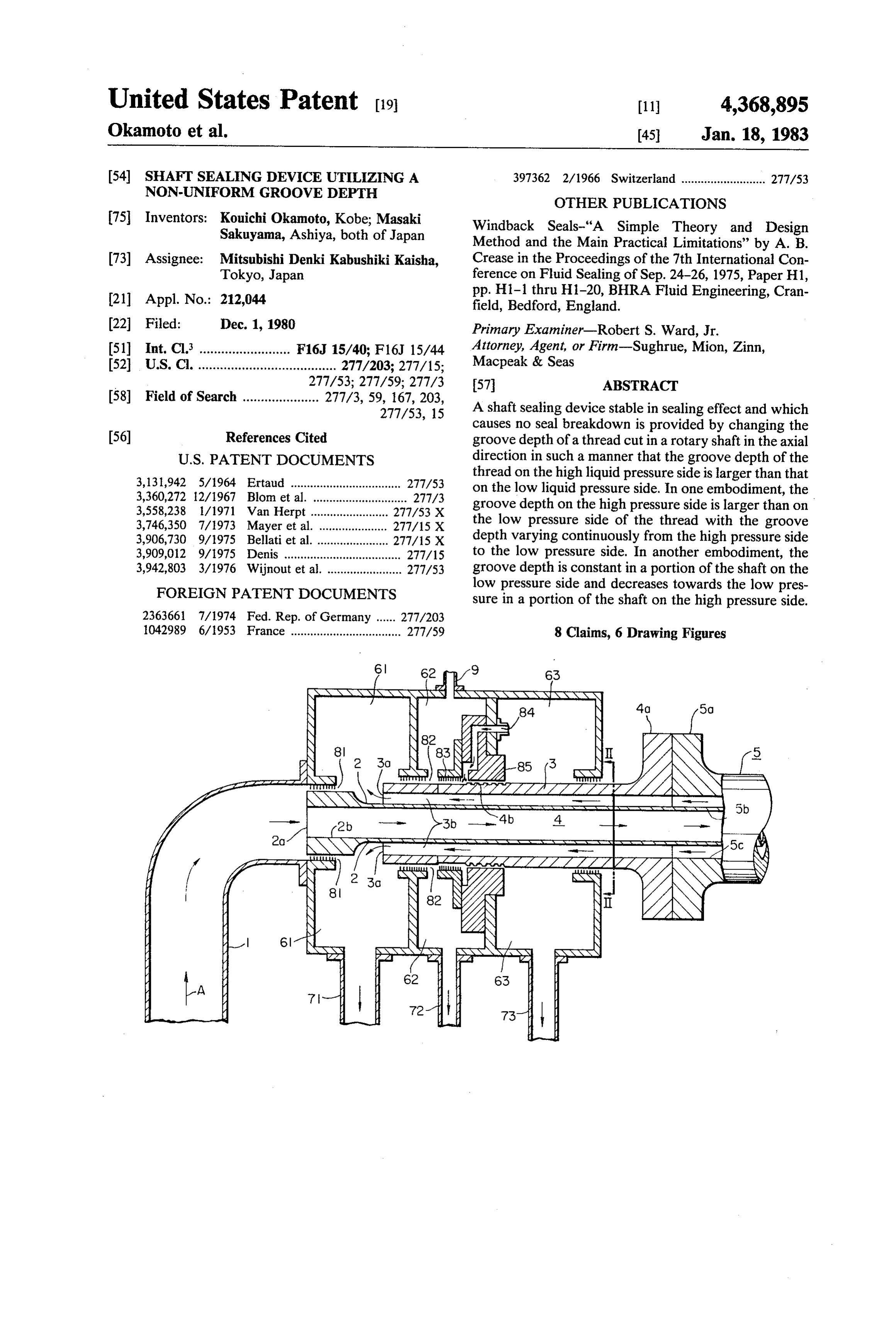
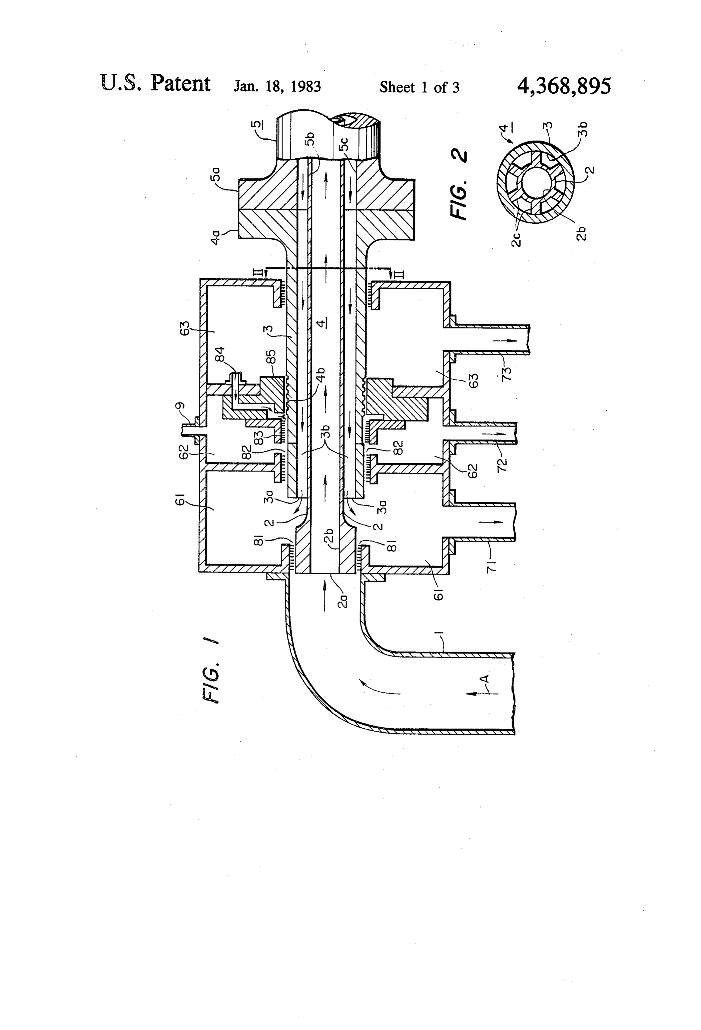
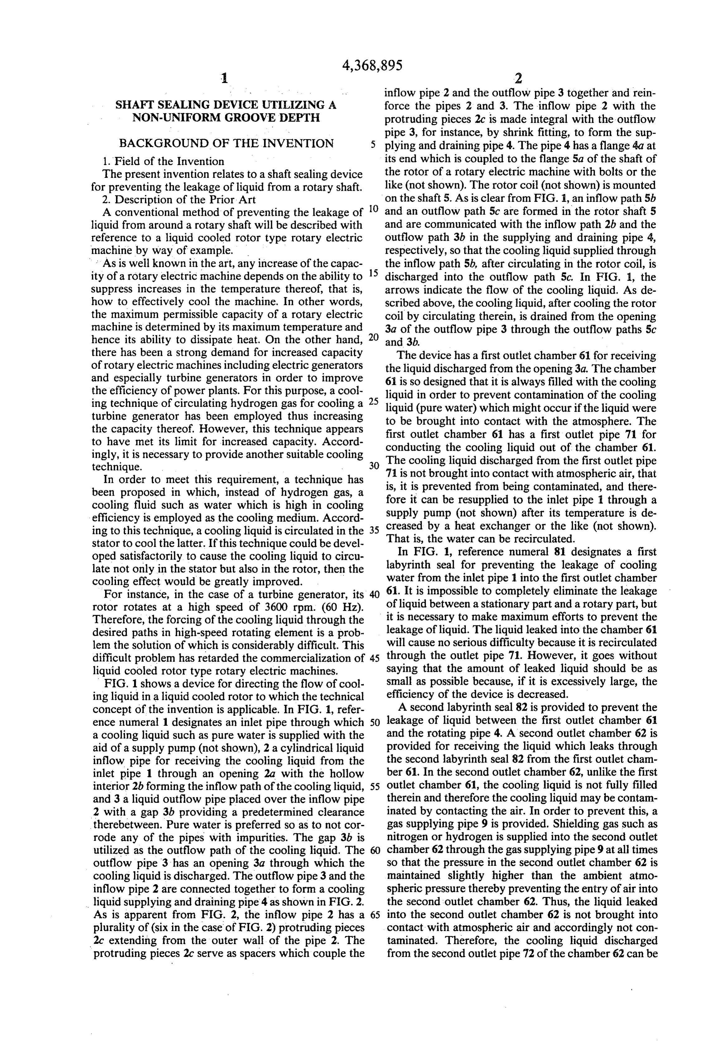
BACKGROUND OF THE INVENTION 5 plying and draining pipe 4. The pipe 4 has a flange 4a at 1. Field of the Invention its end which is coupled to the flange 5a of the shaft of The present invention relates to a shaft sealing device the rotor of a rotary electric machine with bolts or the for preventing the leakage of liquid from a rotary shaft. like (not shown). The rotor coil (not shown) is mounted 2. Description of the Prior Art on the shaft 5. As is clear from FIG. 1, an inflow path 5b A conventional method of preventing the leakage of O and an outflow path 5c are formed in the rotor shaft 5 liquid from around a rotary shaft will be described with and are communicated with the inflow path 2b and the reference to a liquid cooled rotor type rotary electric outflow path 3b in the supplying and draining pipe 4, machine by way of example. respectively, so that the cooling liquid supplied through As is well known in the art, any increase of the capac 15 the inflow path 5b, after circulating in the rotor coil, is ity of a rotary electric machine depends on the ability to discharged into the outflow path 5c. In FIG. 1, the suppress increases in the temperature thereof, that is, arrows indicate the flow of the cooling liquid. As de how to effectively cool the machine. In other words, scribed above, the cooling liquid, after cooling the rotor the maximum permissible capacity of a rotary electric coil by circulating therein, is drained from the opening machine is determined by its maximum temperature and 20 3a of the outflow pipe 3 through the outflow paths 5c hence its ability to dissipate heat. On the other hand, and 3b.
there has been a strong demand for increased capacity The device has a first outlet chamber 61 for receiving of rotary electric machines including electric generators the liquid discharged from the opening 3a. The chamber and especially turbine generators in order to improve 6i is so designed that it is always filled with the cooling the efficiency of power plants. For this purpose, a cool liquid in order to prevent contamination of the cooling ing technique of circulating hydrogen gas for cooling a 25 liquid (pure water) which might occur if the liquid were turbine generator has been employed thus increasing to be brought into contact with the atmosphere. The the capacity thereof. However, this technique appears first outlet chamber 61 has a first outlet pipe 71 for to have met its limit for increased capacity. Accord conducting the cooling liquid out of the chamber 61. ingly, it is necessary to provide another suitable cooling The cooling liquid discharged from the first outlet pipe
In order to meet this requirement, a technique has 71 is not brought into contact with atmospheric air, that is, it is prevented from being contaminated, and there been proposed in which, instead of hydrogen gas, a fore cooling fluid such as water which is high in cooling supplyit can be resupplied to the inlet pipe 1 through a pump (not shown) after its temperature is de efficiency is employed as the cooling medium. Accord ing to this technique, a cooling liquid is circulated in the 35 creased by a heat exchanger or the like (not shown). That is, the water can be recirculated.
stator to cool the latter. If this technique could be devel oped satisfactorily to cause the cooling liquid to circu labyrinthIn FIG. 1, reference numeral 81 designates a first late not only in the stator but also in the rotor, then the water fromseal for preventing the leakage of cooling the inlet pipe 1 into the first outlet chamber cooling effect would be greatly improved.
For instance, in the case of a turbine generator, its 61. It is impossible to completely eliminate the leakage rotor rotates at a high speed of 3600 rpm. (60 Hz). of liquid between a stationary part and a rotary part, but Therefore, the forcing of the cooling liquid through the it is necessary to make maximum efforts to prevent the desired paths in high-speed rotating element is a prob leakage of liquid. The liquid leaked into the chamber 61 lem the solution of which is considerably difficult. This will cause no serious difficulty because it is recirculated difficult problem has retarded the commercialization of 45 through the outlet pipe 71. However, it goes without liquid cooled rotor type rotary electric machines. saying that the amount of leaked liquid should be as FIG. 1 shows a device for directing the flow of cool small as possible because, if it is excessively large, the ing liquid in a liquid cooled rotor to which the technical efficiency of the device is decreased. concept of the invention is applicable. In FIG. 1, refer A second labyrinth seal 82 is provided to prevent the ence numeral 1 designates an inlet pipe through which 50 leakage of liquid between the first outlet chamber 61 a cooling liquid such as pure water is supplied with the and the rotating pipe 4. A second outlet chamber 62 is aid of a supply pump (not shown), 2 a cylindrical liquid provided for receiving the liquid which leaks through inflow pipe for receiving the cooling liquid from the the second labyrinth seal 82 from the first outlet cham inlet pipe 1 through an opening 2a with the hollow ber 61. In the second outlet chamber 62, unlike the first interior 2b forming the inflow path of the cooling liquid, 55 outlet chamber 61, the cooling liquid is not fully filled and 3 a liquid outflow pipe placed over the inflow pipe therein and therefore the cooling liquid may be contam 2 with a gap 3b providing a predetermined clearance inated by contacting the air. In order to prevent this, a therebetween. Pure water is preferred so as to not cor gas supplying pipe 9 is provided. Shielding gas such as rode any of the pipes with impurities. The gap 3b is nitrogen or hydrogen is supplied into the second outlet utilized as the outflow path of the cooling liquid. The chamber 62 through the gas supplying pipe 9 at all times outflow pipe 3 has an opening 3a through which the so that the pressure in the second outlet chamber 62 is cooling liquid is discharged. The outflow pipe 3 and the maintained slightly higher than the ambient atmo inflow pipe 2 are connected together to form a cooling spheric pressure thereby preventing the entry of air into liquid supplying and draining pipe 4 as shown in FIG. 2. the second outlet chamber 62. Thus, the liquid leaked As is apparent from FIG. 2, the inflow pipe 2 has a 65 into the second outlet chamber 62 is not brought into plurality of (six in the case of FIG. 2) protruding pieces contact with atmospheric air and accordingly not con 2c extending from the outer wall of the pipe 2. The taminated. Therefore, the cooling liquid discharged protruding pieces 2c serve as spacers which couple the from the second outlet pipe 72 of the chamber 62 can be
Page 6
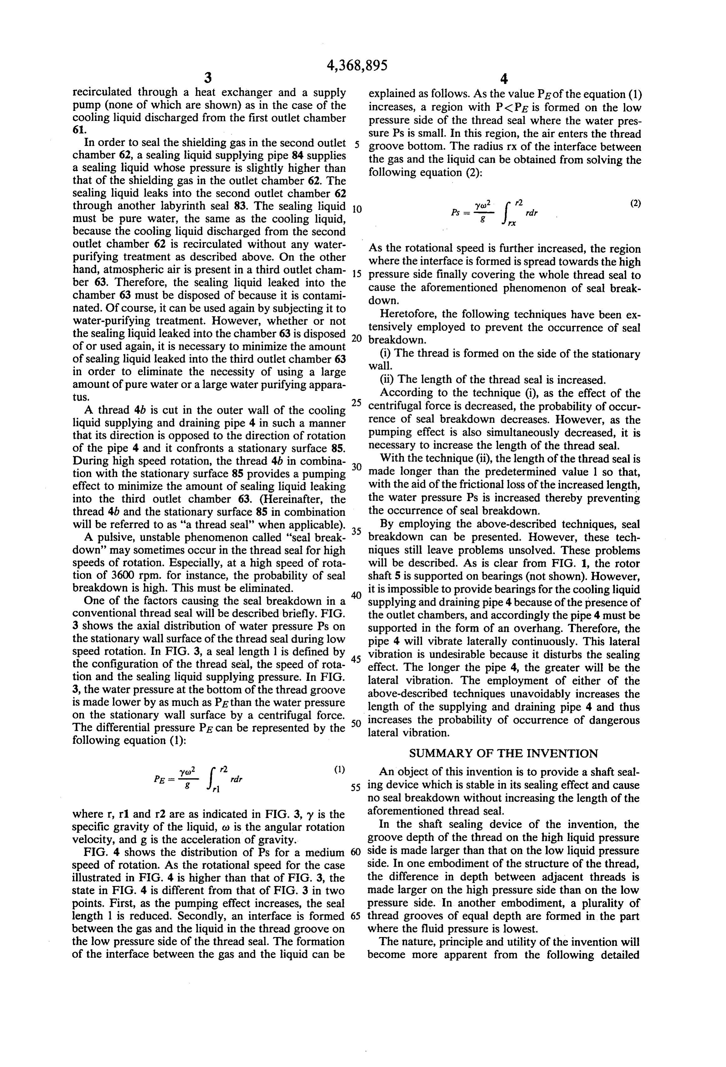
recirculated through a heat exchanger and a supply explained as follows. As the value PE of the equation (1) pump (none of which are shown) as in the case of the increases, a region with PCPE is formed on the low cooling liquid discharged from the first outlet chamber pressure side of the thread seal where the water pres 61. sure Ps is small. In this region, the air enters the thread In order to seal the shielding gas in the second outlet groove bottom. The radius rx of the interface between chamber 62, a sealing liquid supplying pipe 84 supplies the gas and the liquid can be obtained from solving the a sealing liquid whose pressure is slightly higher than following equation (2):
that of the shielding gas in the outlet chamber 62. The sealing liquid leaks into the second outlet chamber 62 through another labyrinth seal 83. The sealing liquid O yo (2) must be pure water, the same as the cooling liquid, because the cooling liquid discharged from the second
outlet chamber 62 is recirculated without any water As the rotational speed is further increased, the region purifying treatment as described above. On the other where the interface is formed is spread towards the high hand, atmospheric air is present in a third outlet cham 15 pressure side finally covering the whole thread seal to ber 63. Therefore, the sealing liquid leaked into the cause the aforementioned phenomenon of seal break chamber 63 must be disposed of because it is contami down.
nated. Of course, it can be used again by subjecting it to Heretofore, the following techniques have been ex water-purifying treatment. However, whether or not tensively employed to prevent the occurrence of seal the sealing liquid leaked into the chamber 63 is disposed 20 breakdown.
of or used again, it is necessary to minimize the amount (i) The thread is formed on the side of the stationary of sealing liquid leaked into the third outlet chamber 63 wall.
in order to eliminate the necessity of using a large amount of pure water or a large water purifying appara (ii) The length of the thread seal is increased. tus. 25
According to the technique (i), as the effect of the
A thread 4b is cut in the outer wall of the cooling centrifugal force is decreased, the probability of occur liquid supplying and draining pipe 4 in such a manner rence of seal breakdown decreases. However, as the that its direction is opposed to the direction of rotation pumping effect is also simultaneously decreased, it is of the pipe 4 and it confronts a stationary surface 85. necessary to increase the length of the thread seal. During high speed rotation, the thread 4b in combina With the technique (ii), the length of the thread seal is tion with the stationary surface 85 provides a pumping 30 made longer than the predetermined value 1 so that, effect to minimize the amount of sealing liquid leaking with the aid of the frictional loss of the increased length, into the third outlet chamber 63. (Hereinafter, the the water pressure Ps is increased thereby preventing thread 4b and the stationary surface 85 in combination the occurrence of seal breakdown.
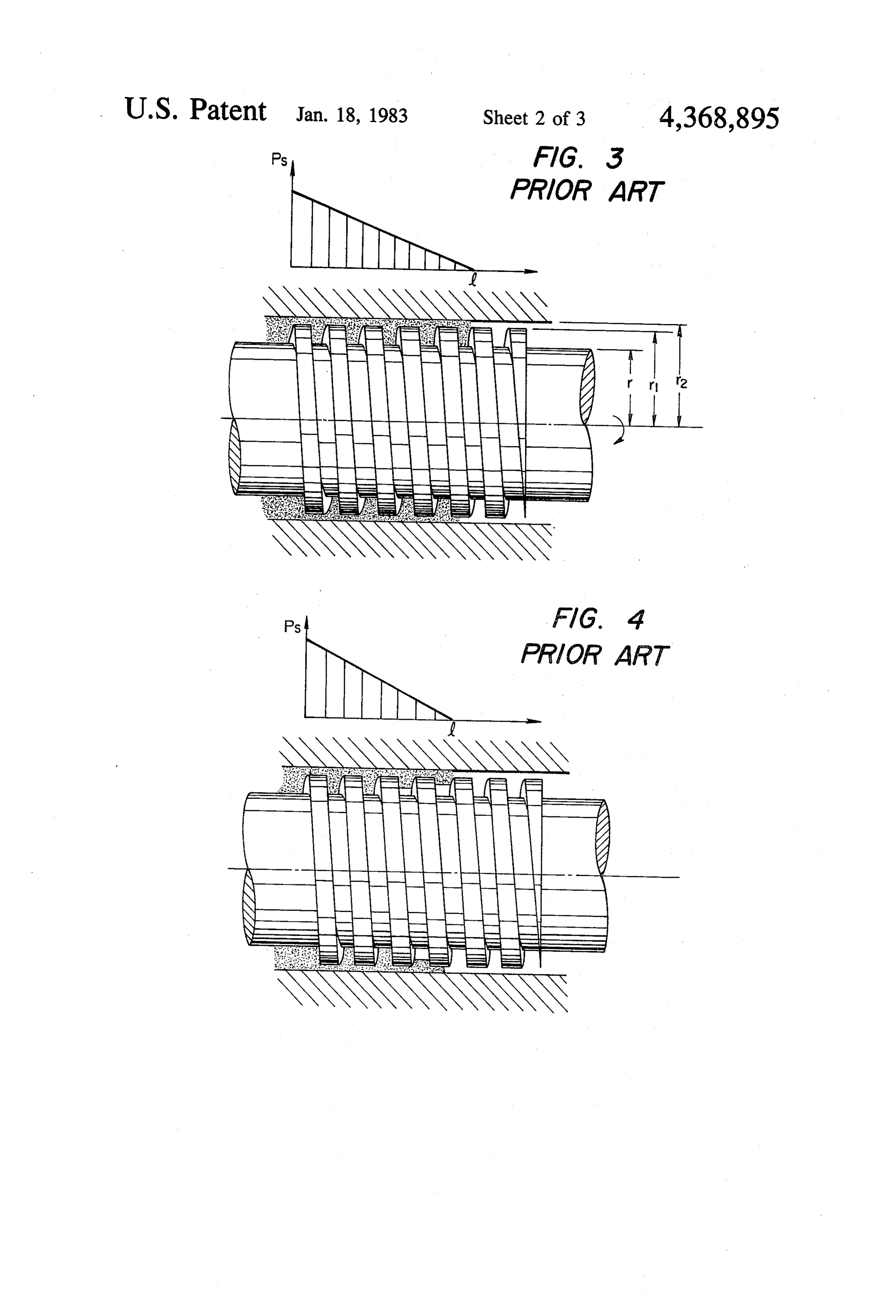
will be referred to as "a thread seal' when applicable). 35 By employing the above-described techniques, seal A pulsive, unstable phenomenon called "seal break breakdown can be presented. However, these tech down' may sometimes occur in the thread seal for high niques still leave problems unsolved. These problems speeds of rotation. Especially, at a high speed of rota will be described. As is clear from FIG. 1, the rotor tion of 3600 rpm. for instance, the probability of seal shaft 5 is supported on bearings (not shown). However, breakdown is high. This must be eliminated. it is impossible to provide bearings for the cooling liquid One of the factors causing the seal breakdown in a supplying and draining pipe 4 because of the presence of conventional thread seal will be described briefly. FIG. the outlet chambers, and accordingly the pipe 4 must be 3 shows the axial distribution of water pressure Ps on supported in the form of an overhang. Therefore, the the stationary wall surface of the thread seal during low pipe 4 will vibrate laterally continuously. This lateral speed rotation. In FIG. 3, a seal length 1 is defined by 45 vibration is undesirable because it disturbs the sealing the configuration of the thread seal, the speed of rota effect. The longer the pipe 4, the greater will be the tion and the sealing liquid supplying pressure. In FIG. lateral vibration. The employment of either of the 3, the water pressure at the bottom of the thread groove above-described techniques unavoidably increases the is made lower by as much as PE than the water pressure length of the supplying and draining pipe 4 and thus on the stationary wall surface by a centrifugal force. 50 increases the probability of occurrence of dangerous The differential pressure PE can be represented by the lateral vibration.
following equation (1):
SUMMARY OF THE INVENTION
yo r2 (1) An object of this invention is to provide a shaft seal
e= r 55 ing device which is stable in its sealing effect and cause no seal breakdown without increasing the length of the where r, r1 and r2 are as indicated in FIG. 3, y is the aforementioned thread seal. specific gravity of the liquid, c) is the angular rotation In the shaft sealing device of the invention, the velocity, and g is the acceleration of gravity. groove depth of the thread on the high liquid pressure FIG. 4 shows the distribution of Ps for a medium side is made larger than that on the low liquid pressure speed of rotation. As the rotational speed for the case side. In one embodiment of the structure of the thread, illustrated in FIG. 4 is higher than that of FIG. 3, the the difference in depth between adjacent threads is state in FIG. 4 is different from that of FIG. 3 in two made larger on the high pressure side than on the low points. First, as the pumping effect increases, the seal pressure side. In another embodiment, a plurality of length 1 is reduced. Secondly, an interface is formed 65 thread grooves of equal depth are formed in the part between the gas and the liquid in the thread groove on where the fluid pressure is lowest.
the low pressure side of the thread seal. The formation The nature, principle and utility of the invention will of the interface between the gas and the liquid can be become more apparent from the following detailed
Page 7
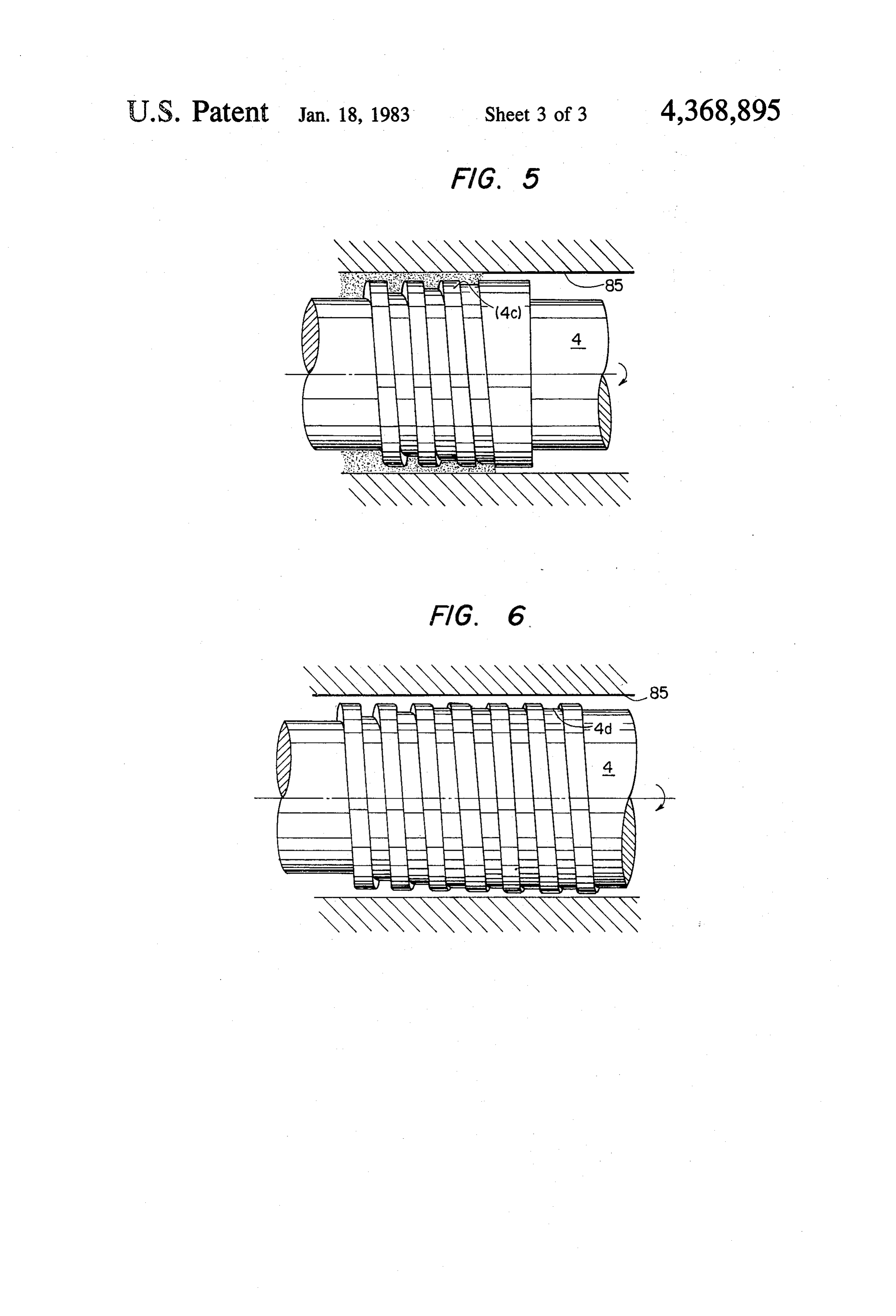
description when read in conjunction with the accom specifically, in FIG. 6, reference numeral 4d designates panying drawings. a thread which is cut in the outer wall of the supplying BRIEF DESCRIPTION OF THE DRAWINGS and draining pipe 4 in such a manner that its direction is In the accompanying drawings opposite to the direction of rotation of the pipe 4. Seal ing is achieved by the thread 4d in association with the
FIG. 1 is a sectional view showing a device for con stationary surface 85.
ducting a cooling liquid in an out of a rotary electric In the embodiment of FIG. 6, the groove depth is machine; made constant on the low pressure side of the thread FIG. 2 is a sectional view taken along line II-II in seal. However, if the groove depth on the lower pres FIG. 1; 10 sure side decreases at a lesser inclination than the incli FIG. 3 is an explanatory diagram showing the distri nation of the groove depth on the high pressure side, the bution of pressure in a conventional thread seal during sealing property for lower speed operation than the low speed rotation;
FIG. 4 is an explanatory diagram showing the distri rated speed is made quite good.
bution of pressure in the conventional thread seal dur 15 concept ofabove-described
In the the invention is embodiments, the technical applied to a device for con ing medium speed rotation; ducting the cooling liquid in and out of the liquid cooled FIG. 5 is an explanatory diagram showing first pre rotary electric machine. However, ferred embodiment of a shaft sealing device constructed applied to all types of rotary shaft the invention can be sealing devices.
according to the invention; and As is apparent from the above description, according FIG. 6 is also an explanatory diagram showing a 20 to the invention, the groove depth of the thread seal is second preferred embodiment of a shaft sealing device changed in the axial direction whereby a shaft sealing constructed according to the invention. device which has a stable sealing effect and which DESCRIPTION OF THE PREFERRED causes no seal breakdown is provided without increas EMBODIMENTS 25 ing the physical length of the thread seal.
What is claimed is:
Referring to FIG. 5, reference numeral 4c designates 1. A shaft sealing device comprising: a thread which is cut in the outer wall of the above described supplying and draining pipe 4 in such a man a rotary shaft in an outer wall of which a thread is ner that its direction is opposite to the direction of rota formed in such a manner that a groove depth tion of the pipe 4 and its thread groove is smaller in 30 thereof changes in an axial direction, said groove depth towards the lower pressure side (the atmospheric depth on the high pressure side of said thread being pressure side). Reference numeral 85 designates a sta larger than that on the low pressure side of said tionary surface which the thread confronts. The sealing thread;
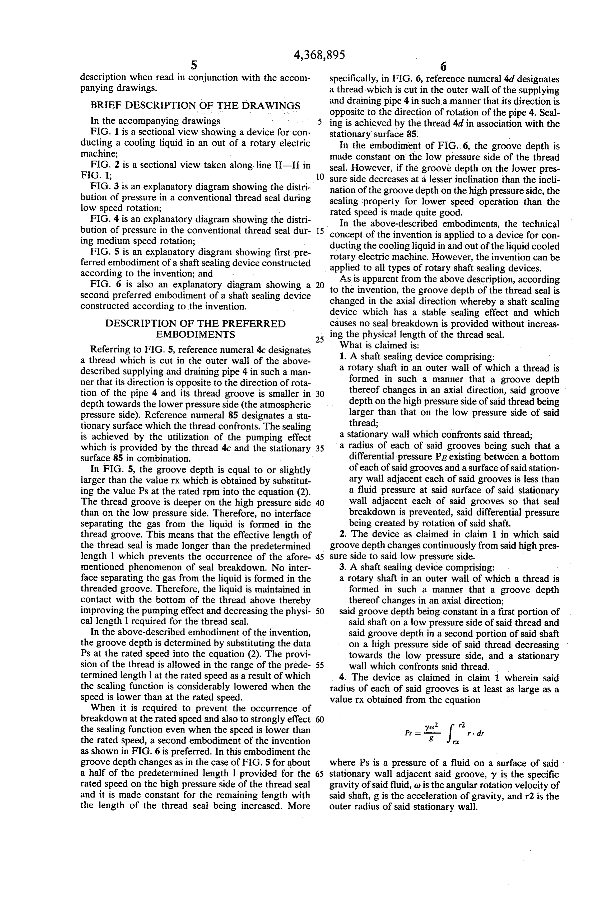
is achieved by the utilization of the pumping effect a stationary wall which confronts said thread; which is provided by the thread 4c and the stationary 35 a radius of each of said grooves being such that a surface 85 in combination. differential pressure PE existing between a bottom In FIG. 5, the groove depth is equal to or slightly of each of said grooves and a surface of said station larger than the value rx which is obtained by substitut ary wall adjacent each of said grooves is less than ing the value Ps at the rated rpm into the equation (2). a fluid pressure at said surface of said stationary The thread groove is deeper on the high pressure side 40 wall adjacent each of said grooves so that seal than on the low pressure side. Therefore, no interface breakdown is prevented, said differential pressure separating the gas from the liquid is formed in the being created by rotation of said shaft. thread groove. This means that the effective length of 2. The device as claimed in claim 1 in which said the thread seal is made longer than the predetermined groove depth changes continuously from said high pres length l which prevents the occurrence of the afore 45 sure side to said low pressure side. mentioned phenomenon of seal breakdown. No inter 3. A shaft sealing device comprising: face separating the gas from the liquid is formed in the a rotary shaft in an outer wall of which a thread is threaded groove. Therefore, the liquid is maintained in formed in such a manner that a groove depth contact with the bottom of the thread above thereby thereof changes in an axial direction; improving the pumping effect and decreasing the physi 50 said groove depth being constant in a first portion of cal length l required for the thread seal. said shaft on a low pressure side of said thread and In the above-described embodiment of the invention, said groove depth in a second portion of said shaft the groove depth is determined by substituting the data on a high pressure side of said thread decreasing Ps at the rated speed into the equation (2). The provi towards the low pressure side, and a stationary sion of the thread is allowed in the range of the prede 55 wall which confronts said thread. termined length at the rated speed as a result of which 4. The device as claimed in claim 1 wherein said the sealing function is considerably lowered when the radius of each of said grooves is at least as large as a speed is lower than at the rated speed. value rx obtained from the equation When it is required to prevent the occurrence of breakdown at the rated speed and also to strongly effect 60 the sealing function even when the speed is lower than the rated speed, a second embodiment of the invention as shown in FIG. 6 is preferred. In this embodiment the groove depth changes as in the case of FIG. 5 for about where Ps is a pressure of a fluid on a surface of said a half of the predetermined length 1 provided for the 65 stationary wall adjacent said groove, y is the specific rated speed on the high pressure side of the thread seal gravity of said fluid, o is the angular rotation velocity of and it is made constant for the remaining length with said shaft, g is the acceleration of gravity, and r2 is the the length of the thread seal being increased. More outer radius of said stationary wall.
Page 8
5. The device as claimed in any one of claims 1, 2, 3 shielding liquid on said high pressure side of said or 4 in which said rotary shaft is adapted for supplying thread.
cooling liquid to the rotor of a rotary electric machine. 7. The device as claimed in claim 1, wherein said 6. A shaft sealing device comprising: groove depth is constant in a first portion of said shaft a rotary shaft in an outer wall of which a thread is on the low pressure side of said thread and said groove formed in such a manner that a groove depth depth in a second portion of said shaft on the high pres thereof changes in an axial direction; sure side of said thread decreases towards the low pres sure side.
a stationary wall which confronts said thread; 8. The shaft sealing device of any one of claims 1, 2, means for forming first, second and third outlet 10 3, 4 or 7 further comprising means for forming first, chambers; second and third outlet chambers; first through fourth first through fourth labyrinth seals, one of said laby labyrinth seals, one of said labyrinth seals being pro rinth seals being provided at each intersection of a vided at each intersection of a wall of each of said outlet wall of each of said outlet chambers and said shaft, chambers and said shaft, said first outlet chamber being said first outlet chamber being filled with a cooling 15 filled with a cooling liquid of the same type as supplied liquid of the same type as supplied through said being through said rotary shaft, said second outlet chamber rotary shaft, said second outlet chamber being par portionpartially of said filled with said cooling liquid in an upper second outlet chamber being coupled to tially filled with said cooling liquid and an upper a source of shielding gas, and said stationary wall being portion of said second outlet chamber being cou 20 disposed between said second and said third outlet pled to a source of shielding gas, and said station chambers; and means for supplying shielding liquid on ary wall being disposed between said second and said high pressure side of said thread.
said third outlet chambers; and means for supplying k k is k
Provenance
- Collection
- Cited prior art
- Original PDF
- patentimages.storage.googleapis.com →
- Filed
- 1980-12-01
- Pages
- 8
- Method
- pdftotext (the PDF's own text layer) + pdftoppm 300dpi page scans
- Source
- Google Patents bibliographic record
- Granted
- 1983-01-18
- Inventors
- Kouichi Okamoto; Masaki Sakuyama; Mitsubishi Electric Corp
- Transcribed from
- patentimages.storage.googleapis.com →