patent · US5696419
High-efficiency electric power generator
9 December 1997
Page 1 — bibliographic record
United States Patent 19 11 Patent Number: 5,696,419 Rakestraw et al. 45 Date of Patent: Dec. 9, 1997 54 HGH-EFFICIENCY ELECTRC POWER 4,318,019 3/1982 Teasley et al. .......................... 310/156 GENERATOR 4,475,075 10/1984 Munn .......................................... 322f1 4,639,626 1/1987 McGee ... ... 310/155 75 Inventors: Thomas G. Rakestraw; Alan E. 4,798.986 1/1989 Smith, Jr. ........ ... 310/268 Rakestraw, both of El Cajon, Calif. 4,866,321 9/1989 Bianchard et al. ..................... 310/12 Primary Examiner-Steven L. Stephan 73 Assignee: Alternative Generation Devices, Inc., Assistant Examiner-Elvin G. Enad
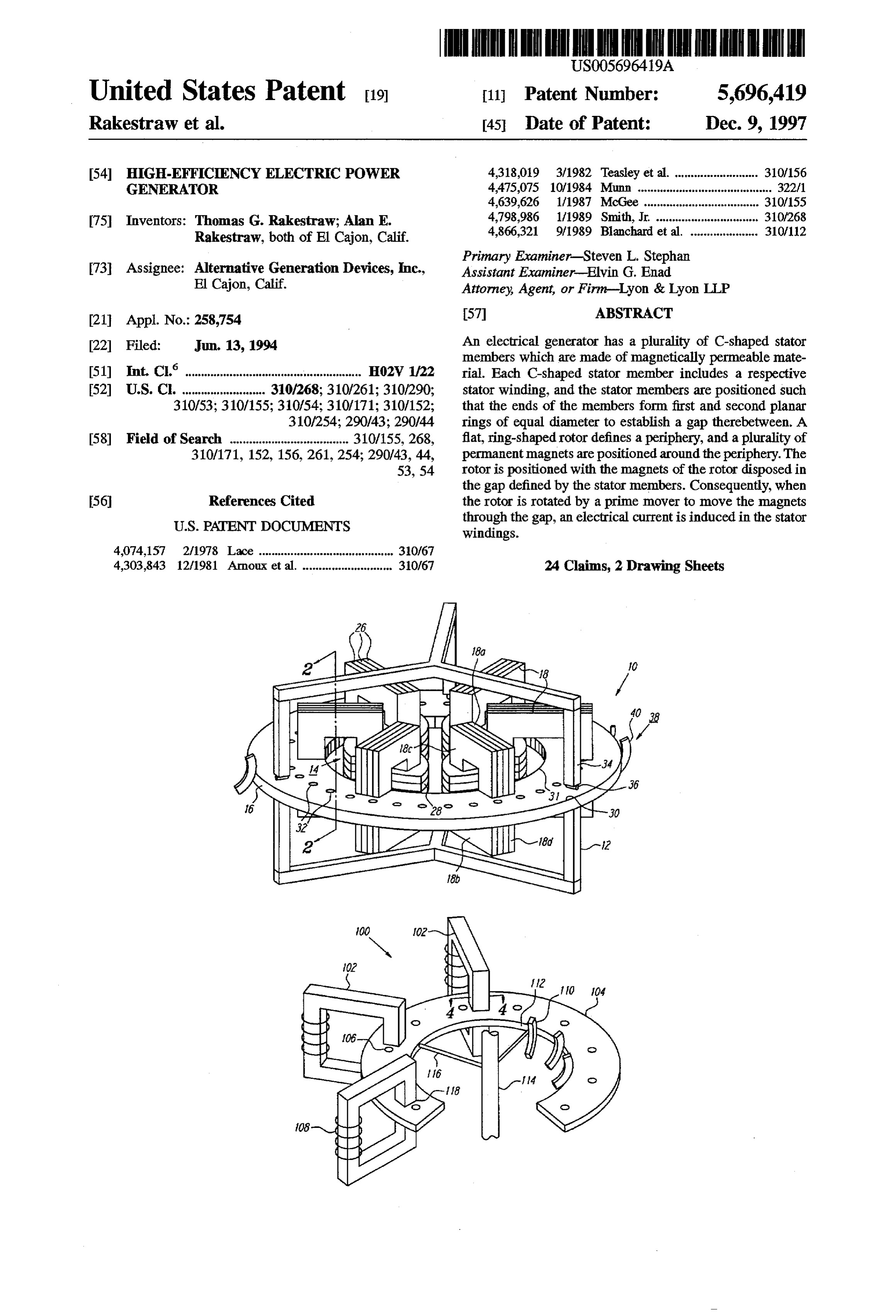
El Cajon, Calif. Attorney, Agent, or Firm-Lyon & Lyon LLP 21 Appl. No.: 258,754 57 ABSTRACT 22 Filed: Jun. 13, 1994 An electrical generator has a plurality of C-shaped stator members which are made of magnetically permeable mate 51 Int, C. HO2W A22 rial. Each C-shaped stator member includes a respective 52) U.S. C. ......................... 310/268; 310/261; 310/290; stator winding, and the stator members are positioned such 310/53; 310/155; 310/54; 310/171; 310/152; that the ends of the members form first and second planar 310/254; 290/43; 290/44 rings of equal diameter to establish a gap therebetween. A 58 Field of Search ..................................... 310/155,268, flat, ring-shaped rotor defines a periphery, and a plurality of 310/171, 152, 156, 261,254; 290/43, 44, permanent magnets are positioned around the periphery. The 53, 54 rotor is positioned with the magnets of the rotor disposed in the gap defined by the stator members. Consequently, when 56 References Cited the rotor is rotated by a prime mover to move the magnets
windings.
4074,157 2/1978 Lace .............. ... 310/67 4,303,843 12/1981 Arnoux et al. .... 30/67 24 Claims, 2 Drawing Sheets
Page 2
Drawing sheet — no readable text.
Page 3
Drawing sheet — no readable text.
Page 4
HIGH-EFFICIENCY ELECTRIC POWER by the C-shaped stator. As taught in McGee, the rotor has GENERATOR alternating regions of magnetically permeable and imper meable material disposed around the periphery of the rotor,
FIELD OF THE INVENTION to change the magnetic flux in the stator and thereby 5 generate an electrical current. In contrast to the present
The present invention relates generally to electrical invention, McGee specifically teaches away from mounting generators, and more particularly to high-efficiency electri the permanent magnets on the rotor. As recognized by the cal generators having a large number of applications. present invention, however, permanent magnets can be BACKGROUND mounted on a rotor to establish an efficient combination of 10 structure for generating electricity.
Many, if not most, existing electrical generators include a Accordingly, it is an object of the present invention to drum-shaped rotor mounted for rotational motion within a provide an electrical generator which is efficient. Another magnetic field which is generated by a surrounding station object of the present invention is to provide an electrical ary stator. The magnetic field ordinarily is generated by an generator which does not require rotating a bulky rotor or electric current which flows through wires, commonly 15 bulky armature windings. Still another object of the present referred to as “field windings”, that are positioned on the invention is to provide an electrical generator which is easy stator. Typically, one or more electrically conductive wires to use and cost-effective to manufacture. referred to as armature windings are wrapped around the rotor, and as the rotor is caused to rotate within the stator by SUMMARY OF THE INVENTION a prime mover (e.g., a turbine-driven shaft), the relative 20 An electric power generator includes a stator made of a motion of the armature windings within the magnetic field plurality of stator members, and the stator members are in produces an electrical output current in the armature wind turn made of material which is characterized by high mag ings. netic permeability. In accordance with the present invention, In such generators, electrical contacts are mounted on the 25 each stator member is formed with a back side element that rotor and complementary stationary contacts, often referred is wound with electrically conductive wire. Also, each stator to as "brushes" or "sliprings”, are mounted around the rotor. member is formed with opposed top and bottom elements As the rotor turns, the electrical contacts of the rotor move which are connected to the back side element and which past the brushes or slip rings, contacting the brushes/slip extend perpendicularly away from the back side element to rings as they do so to thereby provide a circuit for electricity 30 establish a gap between the top and bottom elements. to traverse from the armature to a load that is external to the A wheel-shaped rotor defines a periphery and has at least generator. one permanent magnet mounted thereon. As intended by the It will be appreciated that slip rings and brushes can present invention, the rotor is rotatably mounted such that become worn and abraded, and they accordingly require the magnet passes between successive gaps in the stator periodic maintenance and replacement. Furthermore, elec 35 when the rotor is rotated with respect to the stator. trical sparking is often generated as the armature contacts Preferably, the rotor is thin, flat, and ring-shaped. move past the brushes, creating a safety hazard. Moreover, In one presently preferred embodiment, a plurality of generator efficiency is degraded in such machines by the permanent magnets are mounted in a circular pattern on the electrical resistance of the brushes and by mechanical fric rotor. Additionally, each stator member is generally tion loss from the drag of the brushes on the rotor. C-shaped, and each stator member is made of a plurality of Additionally, the presence of the relatively heavy armature thin, flat, C-shaped stator elements, with each stator element windings on the rotor makes the rotor more difficult to rotate being held flush against its immediately adjacent stator than would otherwise be the case, further reducing the elements.
efficiency of the generator. To support the rotor, a plurality of bearings are juxtaposed To address some of the drawbacks noted above with 45 with the rotor and bear against the rotor. Furthermore, arotor conventional generators, a device known as the inductor driver is coupled to the rotor to cause the rotor to rotate. The alternator has been introduced. In the inductor alternator, rotor driver preferably includes at least one vane against permanent magnets are mounted on the stator, and the which fluid can be directed to cause the rotor to rotate. As armature windings are also located on the stator. envisioned by the present invention, the vane can be a Unfortunately, inductor alternators tend to be bulky and 50 turbine blade, windmill vane, or vehicle-mounted vane for inefficient. turning the rotor when wind is directed against the vane. Other generators have attempted to address the problems In one embodiment, the periphery of the rotor surrounds associated with inductor alternators noted above by estab the back side elements of the stator members. In another lishing the armature on the stator and mounting permanent embodiment, the periphery of the rotoris surrounded by the magnets on a drum-shaped rotor, thereby removing the need 55 back side elements of the stator members. for field windings. Unfortunately, however, voltage regula In another aspect of the present invention, an apparatus tion in such generators is difficult, and the magnet mounts for generating electricity includes a stator made of magneti cannot easily withstand high rotational speeds. Also, owing cally permeable material, and the stator defines an annular to the number of small magnets which must be bound gap. An electrically conductive winding is positioned in together on a large drum-shaped rotor which must in turn be electro-magnetic engagement with the stator. Additionally, a precisely positioned within a stator, assembly of such plurality of permanent magnets are disposed adjacent the devices is difficult at best. winding for generating a magnetic field, and a shaftless One solution to the problems noted above has been rotatable rotoris movably disposed relative to the stator such disclosed in U.S. Pat. No. 4639,626 to McGee. McGee that when the rotor is rotated relative to the stator an electric proposes mounting both the armature and field-establishing 65 current is generated in the winding.
permanent magnets on a stator having a C-shaped cross In yet another aspect of the present invention, a generator section, and then rotating a rotor through the gap established of electricity includes a magnetically permeable stator which
Page 5
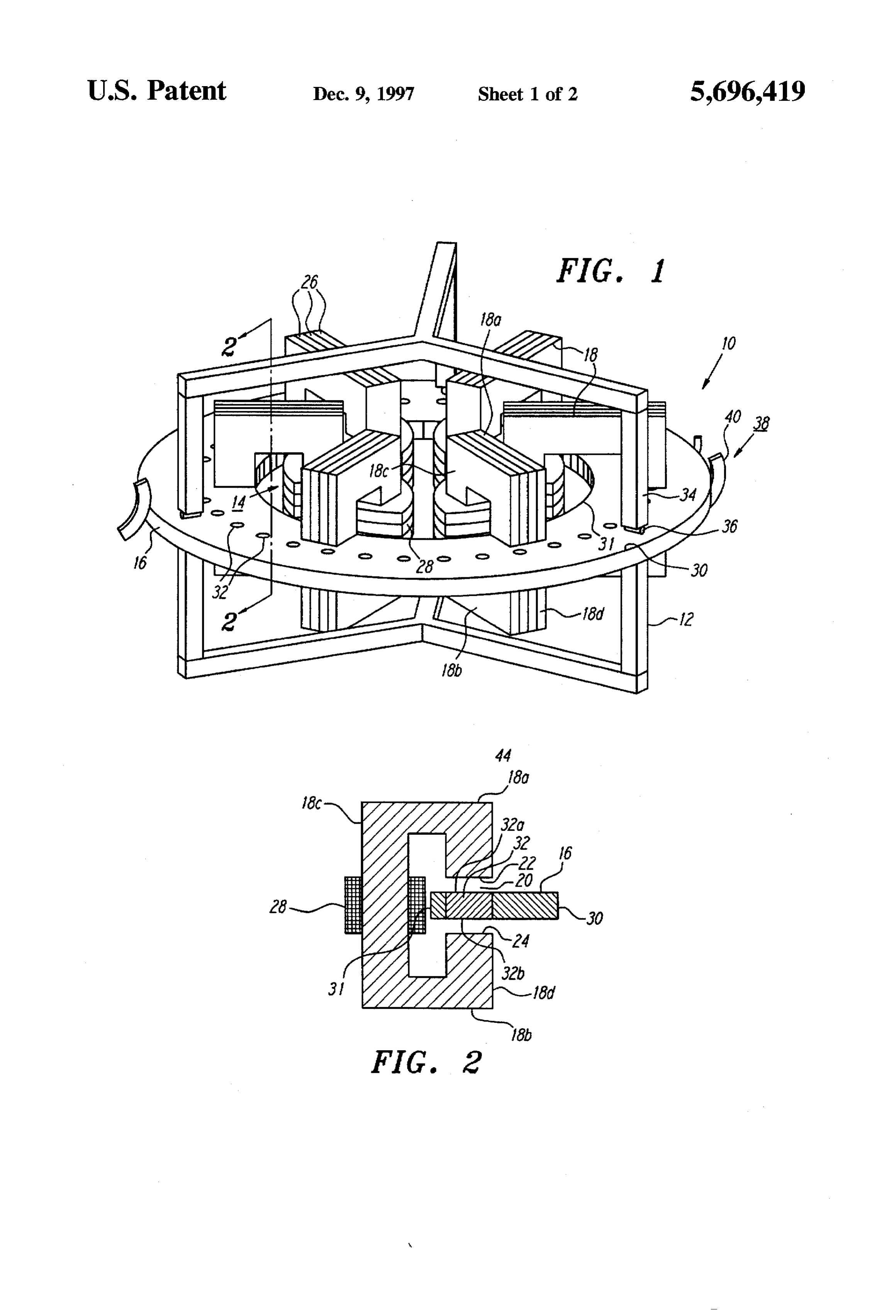
forms first and second planar rings of equal diameter. The plurality of thin, flat, generally C-shaped stator elements 26, rings define a central axis, and the rings are generally with each stator element 26 of a particular stator member 18 parallel and axially spaced from each other to establish a gap being held flush against its immediately adjacent stator therebetween. At least one stator winding is engaged with elements 26. The stator elements 26 are made of a material the stator. Moreover, a circularly-shaped rotor has alternat which is characterized by high magnetic permeability, e.g., ing regions of magnetized and unmagnetized material. O.
Importantly, the rotor is disposed for rotation about the FIGS. 1 and 2 also show that an electrically conductive central axis with the regions of magnetized and unmagne armature winding 28 is wrapped around a respective back tized material disposed generally on the periphery of the side element 18d. It is to be understood that the armature rotor for movement within and through the gap to thereby 10 windings 28 can be electrically connected in a predeter induce an electrical current in the stator winding. mined manner, e.g., series, parallel, delta, etc. to provide an The details of the present invention, both as to its structure electrical output having the desired phases, currents, and operation, can best be understood with reference to the voltages, and waveforms. The number of turns per armature accompanying drawings, in which like reference numerals winding 28 and the nature of the interconnections from refer to like parts, and in which: 15 winding 28 to winding 28 may be established to accommo date the desired electrical output characteristics. It will be
BRIEF DESCRIPTION OF THE DRAWINGS further understood that the stator elements 26 that establish FIG. 1 is a perspective view of the generator of the present a stator member 18 are held together by the armature invention, with portions broken away for clarity and with the 20 windings 28 of the respective suitor member 18. Further, wanes shown schematically; after the armature windings 28 are wound around the associated stator member 18, the stator member 18 can be
FIG. 2 is a cross-sectional view, as seen along the line shellaqued 2-2 in FIG. 1; to further hold the stator elements 26 together.
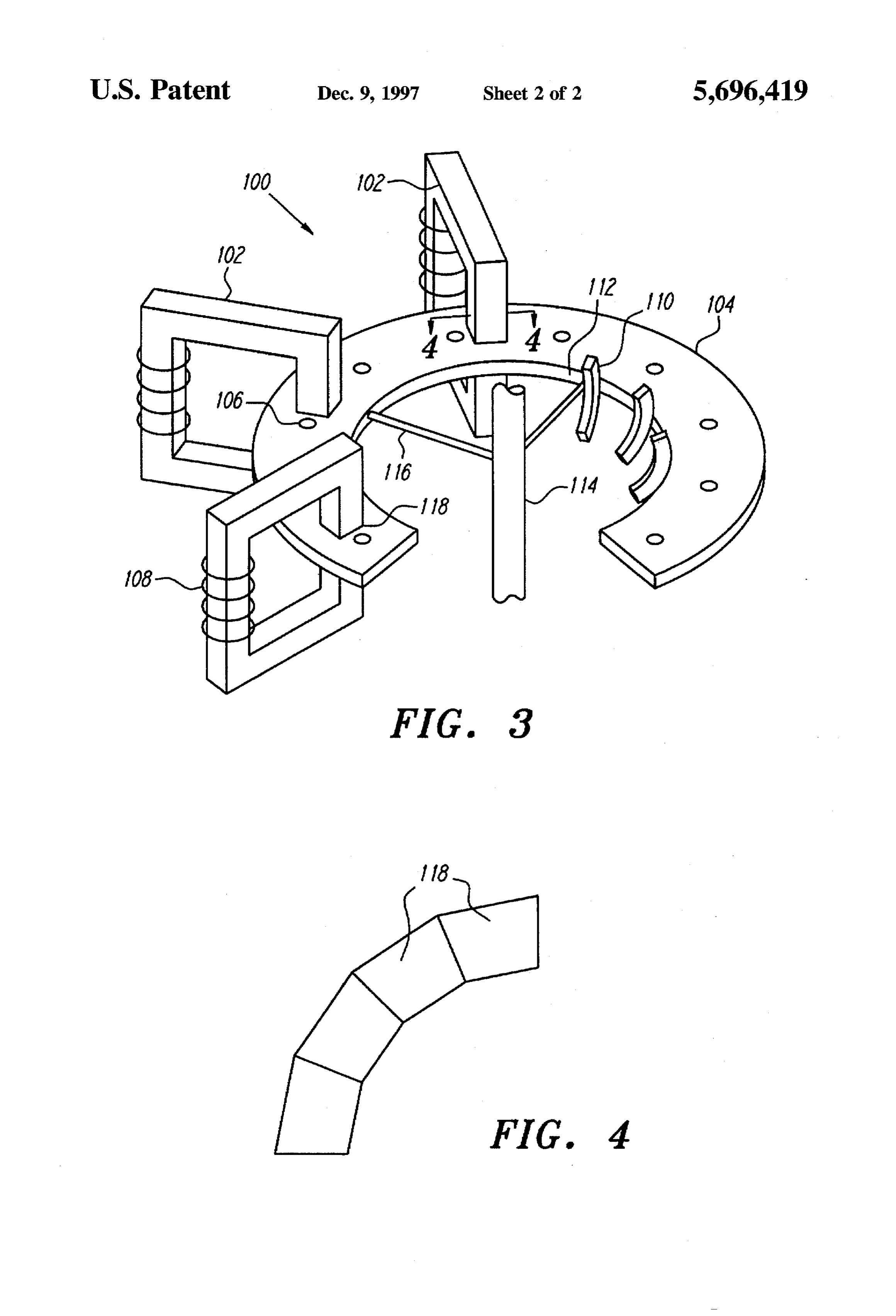
FIG. 3 is a perspective view of an alternate embodiment wheel-shaped, and is preferablyto FIGS. 1 and 2, the rotor 16 is of the generator of the present invention, with portions 25 Accordingly, the rotor 16 definesthin, an flat, and ring-shaped.
outer periphery 30 and broken away for clarity and with the vanes shown schemati an inner periphery 31, and, as shown in FIGS. 1 and 2, a cally; and plurality of cylindrically-shaped permanent magnets 32 are FIG. 4 is a cross-sectional view of the open ends of mounted on the rotor 16 in a circular pattern generally on or several stator members, as would be seen along the line 4-4 near the outer periphery 30 of the rotor 16. Preferably, the in FG, 3. 30 magnets 32 are made of a suitable high-strength permanent
DETALED DESCRIPTION OF THE magnetic material, such as rare earth cobalt or neodymium PREFERRED EMBODIMENTS ferrite, while the rotor 16 is made of a lightweight material characterized by low magnetic permeability, e.g., hard plas
Referring initially to FIG. 1, an electric power generator tic or aluminum.
is shown, generally designated 10. As shown, the generator 35, Each permanent magnet 32 has a north pole face 32a 10 includes a base 12 and a stator, generally designated 14, (FIG. 2) and an opposed south pole face 32b, and the north stationarily mounted on the base 12. A shaftless rotor 16 is pole faces 32a of the magnets 32 are oriented in the same rotatably mounted on the base 12, and the rotor 16 can turn direction as each other (i.e., upwardly in FIGS. 1 and 2). relative to the stator 14. Likewise, the south pole faces 32b of the magnets 32 are As shown in FIG. , the stator 14 includes a plurality of, oriented in the same direction as each other (i.e., down preferably six (6), stator members 18. It is to be understood, wardly in FIGS. 1 and 2).
however, that the stator 14 can include fewer or greater As can be appreciated in reference to FIG. 1, the radius of stator members 18. As shown, each stator member 18 is the circle defined by the magnets 32 is established such that configured generally like a block-style letter "C". 45 the magnets 32 pass between successive gaps 20 in the stator Accordingly, each stator member 18 has parallelepiped 14 when the rotor 16 is rotated with respect to the stator 14. shaped top and bottom elements 18a, 18b which are parallel As the skilled artisan will appreciate, when the rotor 16 is with each other, a parallelepiped-shaped back side element rotated to cause the magnets 32 to pass through the gaps 20 18c extending perpendicularly between the top and bottom of the stator members 18, electricity is generated in the elements 18a, 18b, and afront side element 18d having a gap 50 armature windings 28.
20 formed therein. Together, the individual gaps 20 of the In the presently preferred embodiment, the magnets 32 are stator members 18 define an annular gap. press-fit into receiving holes formed or machined in the rotor Stated differently, each from side element 18d is formed 16. As shown, each magnet 32 extends through the entire with a top surface 22 and a bottom surface 24 (FIG. 2), and width of the rotor 16, as measured axially, though they may as can be appreciated in cross-reference to FIGS. 1 and 2 the 55 extend more or less than the width of the rotor 16. In the front surfaces 22 together define a first planar ring. As can embodiment shown in FIG. 2, the north pole faces 32a and be further appreciated in reference to FIGS. 1 and 2, the south pole faces 32b of the magnets 32 are flush with the bottom surfaces 24 together define a second planar ring, and surface of the rotor 16. The shape, size, number, material, the first and second planar rings are parallel, are of equal and properties of the magnets 32 may vary depending on diameter, and are concentric (i.e., they share a common waveform and magnitude of electrical output desired, as axis). well as other design considerations. In the embodiment shown in FIG. 1, the open portion of The rotor 16 may be rotatably mounted on the base 12 by the "C" defined by each stator member 18 is oriented any suitable means, including the means shown in FIG.1. As outwardly. In other words, the rotor 16 surrounds the back shown, a plurality of bearing supports 34 are attached to or side elements 18c of the stator members 18. 65 formed integrally with the base 12, and each bearing support FIG. 1 additionally shows that in the presently preferred rotatably supports a respective round or cylindrical bearing embodiment, each stator member 18 is established by a roller 36. In reference to FIG. 1, bearing rollers 36 are
Page 6
S 6 provided on top of and below the rotor 16 and abut the rotor the present invention, the rotor 104 shown in FIG. 3, like the 16 to support the rotor 16. rotor 16 shown in FIG. 1, is a shaftless rotor in the sense that As the skilled artisan will appreciate, apart from the a rotor shaft is not required to permit operation of the particular means used to support the rotor 16, the rotor 16 is generator 100.
shaftless, and is driven, as disclosed below, by urging FIG. 3 shows that each stator member 102 includes a top against the rotor 16. Consequently, a mechanical advantage surface 118 which faces the rotor 104 and which is closely in turning the rotor 16 is gained vis-a-vis a shaft-driven includesspaced from the rotor 104. Also, each stator member 102 a bottom surface that is opposed to the top surface rotor. As a further consequence of the shaftless design of the (bottom surfaces rotor 16, operability of the generator 10 is possible at top surfaces 118 of not shown in FIG. 1). FIG.3 shows that the relatively low rotor 16 rotational speeds. Moreover, the drag 10 from each other, butthe stator members 102 are spaced apart experienced in turning the rotor 16 may not appreciably 102 alternatively can beshown as in FIG. 4, the stator members positioned close together around the increase with increasing rotational speeds. Additionally, any rotor 104 with their top surfaces 118 contiguous with each counter electromotive force (emf) generated by current in other. In such an embodiment, the bottom surfaces of the the armature windings 28 will tend to reduce power output, stator members 102 would also be contiguous. Stated but will have little, if any, effect on the drag experienced in differently, in the embodiment shown in FIG. 4, the
top rotating the rotor 16. Furthermore, output voltage of the surfaces 118 of the stator members 102 establish a first generator 10 tends to be relatively stable. Also, the generator continuous ring-shaped surface, while the bottom surfaces 10 can effectively generate electricity at relatively low (e.g., of the stator members 102 establish a second continuous 600 RPM) rotational speeds. ring-shaped surface.
Still referring to FIG. 1, a rotor driver, generally desig 20 To facilitate positioning the stator members 102 closely nated 38 is operably coupled to the rotor to the rotor 16 to together as shown in FIG. 4, the top surfaces 118 of the stator cause the rotor 16 to rotate. In one embodiment, the rotor members 102 can be wedge-shaped. In other words, as driver 38 includes a plurality of vanes 40. Fluid can be shown in FIG. 4, the top surfaces 118 can be trapezoidal directed against the vanes 40 to cause the rotor 16 to rotate. shaped, with the long base of each trapezoid oriented Accordingly, the rotor driver 40 can be a turbine or wind 25 outwardly and the short based positioned radially inwardly mill. Alternatively, the base 12 can be mounted on a vehicle, of the associated long base.
and wind can urge against the vanes 40 to cause the rotor 16 While the particular high-efficiency electric power gen to rotate. While FIG. 1 shows only three vanes 40, it is to be erator as herein shown and described in detail is fully understood that many more vanes 40 can be attached to the capable of attaining the above-described objects of the rotor 16 around the entire length of the outer periphery 30 of 30 invention, it is to be understood that it is the presently the rotor 16. preferred embodiment of the present invention and is thus As best shown in FIG. 2, the output voltage of the representative of the subject matter which is broadly con generator 10 can be controlled by varying a DC current in templated by the present invention, that the scope of the coils 44 which can be located anywhere on a respective one 35 present invention fully encompasses other embodiments of the stator members 18. Alternatively, voltage may be which may become obvious to those skilled in the art, and controlled by a group of switches (not shown) connecting a that the scope of the present invention is accordingly to be variable number of winding 28 turns directly to output limited by nothing other than the appended claims. terminals. As yet another alternative, a rectifier (not shown) What is claimed is:
may be operably connected to the output of the generator 10 1. An electric power generator, comprising: to control voltage. The DC current, opening and closing of a stator including a plurality of stator members made of the switches, or rectifier may be controlled using conven material characterized by high magnetic permeability, tional voltage regulator methods and devices. each stator member having a back side element wound FIG.3 shows an alternate embodiment of the generator of with electrically conductive wire and opposed top and the present invention, generally designated 100, which has a 45 bottom elements connected to the back side element plurality of "C"-shaped stator members 102, a rotor 104, and and extending perpendicularly away therefrom to a plurality of permanent magnets 106 mounted on the rotor establish a gap between the top and bottom elements; 104. The generator 100 shown in FIG. 3 is substantially a wheel-shaped shaftless rotor defining a periphery and identical to the generator 10 shown in FIG. 1, except that the having at least one permanent magnet mounted opening of the “C” established by each stator member 102 50 thereon, said rotor circumscribing a hollow circular is oriented inwardly, i.e., the periphery of the rotor 104 is region within which said stator members are at least surrounded by the closed sides of the stator members 102. partially positioned, wherein the rotor is rotatably Consequently, cooling of stator-mounted armature windings mounted such that the magnet passes between succes 108 is facilitated. sive gaps in the stator when the rotor is rotated with Additionally, a plurality of vanes 110 are mounted on an 55 respect to the stator; and inner periphery 112 of the rotor 104. Accordingly, fluid may a rotor, driver coupled directly to the periphery of the be directed through the annular rotor 104 against the vanes rotor said rotor driver comprising at least one vane 110 to cause the rotor 104 to rotate relative to the stator against which an external fluid force can be applied to members 102, thereby generating electricity in the armature cause the rotor to rotate.
windings 108. 60 2. The generator of claim 1, further comprising a plurality If desired, the rotor 104 may be connected to a central of permanent magnets mounted in a circular pattern on the support 114 via connecting arms 116 for supporting the rotor roto.
104. Unlike the drive shafts of conventional generators, 3. The generator of claim 2, wherein each stator member however, the central support 114 does not impart torque to is generally C-shaped, and each stator member is made of a the rotor 104, but is merely used as one means for supporting 65 plurality of thin, flat, C-shaped stator elements, each stator the rotor 104. Other means of supporting the rotor 104 may element positioned flush against its immediately adjacent be used in lieu of the central support 114. Thus, as intend by stator elements.
Page 7
4. The generator of claim 3, wherein the stator members 16. The apparatus of claim 15, further comprising a are electrically connected with each other in parallel. plurality of bearings juxtaposed with the rotor for supporting 5. The generator of claim 3, wherein the stator elements the rotor.
are electrically connected together in series. 17. The apparatus of claim 13, wherein said inner periph 6. The generator of claim 1, wherein the wheel-shaped 5 ery defines a circular plane, and wherein each stator member rotor is thin, flat, and ring-shaped. is generally C-shaped, said stator members being disposed 7. The generator of claim 6, further comprising a plurality in a radial pattern with respect to the center of said circular of bearings juxtaposed with the rotor for supporting the plane such that the backside element of each stator member roto.
passes through said circular plane and the annular gap of 8. The generator of claim 1, wherein the vane is a turbine O each stator member surrounds said rotor, blade.
9. The generator of claim 1, wherein the vane is a rotatably 18. The apparatus of claim 12, wherein said rotor is windmill vane extending outward from the periphery of said to a base.mounted between a plurality of bearings connected rotor and the external fluid force is air moving relative to the generator. 15 19. A generator of electricity, comprising: 10. The generator of claim 6, wherein the periphery of the a magnetically permeable stator forming first and second rotor surrounds the back side elements of the stator mem planar rings of equal diameter and defining a central bers. axis, the rings being generally parallel and axially 11. The generator of claim 1, wherein said rotor is spaced from each other to establish a gap therebetween: rotatably mounted between a plurality of bearings connected 20 at least one stator winding engaged with the stator; to a base.
12. An apparatus for generating electricity, comprising: a circularly-shaped shaftless rotor having alternating regions of magnetized and unmagnetized material, the a stator made of magnetically permeable material, the rotor disposed for rotation about the central axis and stator defining an annular gap; around the stator, with the regions of magnetized and
an electrically conductive winding in electro-magnetic unmagnetized material disposed generally on the engagement with the stator; periphery of the rotor for movement within and through a plurality of permanent magnets disposed adjacent the the gap to thereby induce an electrical current in the winding for generating a magnetic field, said plurality stator winding; and of permanent magnets mounted on a shaftless rotatable a rotor driver coupled directly to the periphery of the rotor movably disposed relative to the stator such that rotor, said rotor driver comprising at least one vane when the rotor is rotated relative to the stator an electric against which an external fluid force can be applied to current is generated in the winding, said rotor having a cause the rotor to rotate.
flat shape and central opening defining an inner periph 20. The generator of claim. 19, wherein the stator includes ery surrounding said stator; and 35 a plurality of stator members made of material characterized a rotor driver coupled directly to the periphery of the by high magnetic permeability, each stator member having rotor, said rotor driver comprising at least one vane a back side element wound with electrically conductive wire against which an external fluid force can be applied to and opposed top and bottom elements connected to the back cause the rotor to rotate. side element and extending perpendicularly away therefrom 13. The apparatus of claim 12, wherein the magnets are to establish the annular gap between the top and bottom mounted on the rotor in a circular pattern such that the elements.
magnets pass through the gap of the stator when the rotor is 21. The generator of claim 20, wherein each stator mem rotated, and wherein the stator includes a plurality of stator ber is generally C-shaped, and each stator member is made members made of material characterized by high magnetic of a plurality of thin, flat, C-shaped stator elements, each permeability, each stator member having a back side element 45 stator element positioned flush against its immediately adja wound with electrically conductive wire and opposed top cent stator elements.
and bottom elements connected to the back side element and 22. The generator of claim 19, wherein the rotor is thin, extending perpendicularly away therefrom to establish the flat, and ring-shaped.
annular gap between the top and bottom elements. 23. The generator of claim 20, wherein the rotor defines 14. The apparatus of claim 13, wherein each stator mem 50 an inner periphery, and the inner periphery of the rotor ber is generally C-shaped, and each stator member is made surrounds the back side elements of the stator members. of a plurality of thin, flat, C-shaped stator elements, each 24. The generator of claim. 19, wherein said rotor is stator element positioned flush against its immediately adja rotatably mounted between a plurality of bearings connected cent stator elements. to a base.
15. The apparatus of claim 14, wherein the rotor is thin, flat, and ring-shaped.
Provenance
- Collection
- Cited prior art
- Original PDF
- patentimages.storage.googleapis.com →
- Filed
- 1994-06-13
- Pages
- 7
- Method
- pdftotext (the PDF's own text layer) + pdftoppm 300dpi page scans
- Source
- Google Patents bibliographic record
- Granted
- 1997-12-09
- Inventors
- Thomas G. Rakestraw; Alan E. Rakestraw; Alternative Generation Devices Inc
- Transcribed from
- patentimages.storage.googleapis.com →