patent · US3746349
Mechanical seals and or thrust bearings
17 July 1973
Page 1 — bibliographic record
United States Patent (19) [11] 3,746,349 Smale et al.
54 MECHANICAL SEALS AND/OR THRUST 57 ABSTRACT
BEARINGS
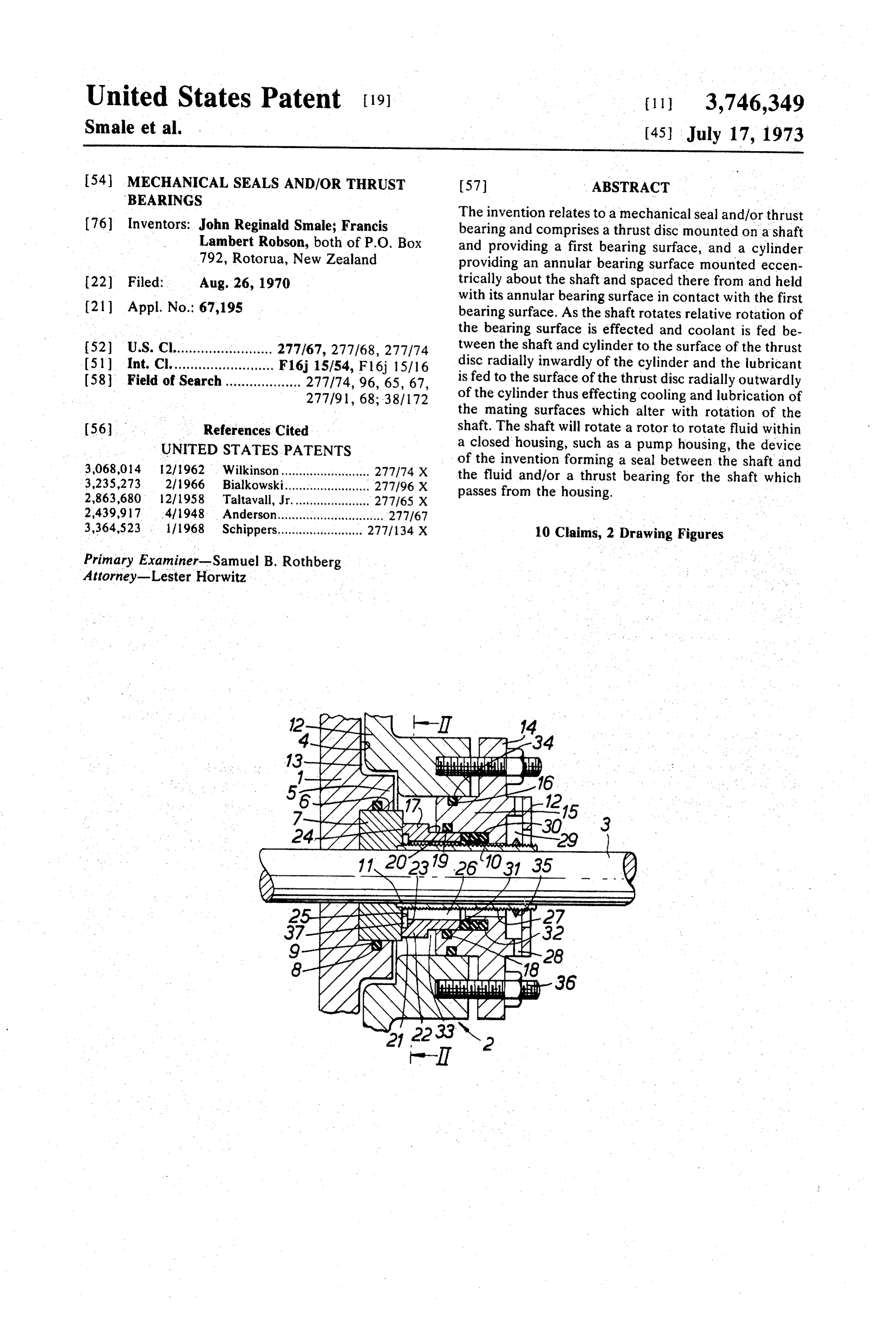
The invention relates to a mechanical seal and/or thrust 76) Inventors: John Reginald Smale; Francis bearing and comprises a thrust disc mounted on a shaft Lambert Robson, both of P.O. Box and providing a first bearing surface, and a cylinder 792, Rotorua, New Zealand providing an annular bearing surface mounted eccen 22 Filed: Aug. 26, 1970 trically about the shaft and spaced there from and held with its annular bearing surface in contact with the first (21) Appl. No.: 67,195 bearing surface. As the shaft rotates relative rotation of the bearing surface is effected and coolant is fed be 52 U.S. Cl......................... 277/67, 277/68, 277/74 tween the shaft and cylinder to the surface of the thrust (51) Int. Cl.......................... F16j 15/54, F16, 15/16 disc radially inwardly of the cylinder and the lubricant 58 Field of Search................... 277/74, 96, 65, 67, is fed to the surface of the thrust disc radially outwardly 277/91, 68; 387172 of the cylinder thus effecting cooling and lubrication of the mating surfaces which alter with rotation of the (56 References Cited shaft. The shaft will rotate a rotor to rotate fluid within UNITED STATES PATENTS a closed housing, such as a pump housing, the device 3,068,014 12/1962. Wilkinson......................... 277f74 X of the invention forming a seal between the shaft and 3,235,273 2/1966 Bialkowski........................ 277/96 X the fluid and/or a thrust bearing for the shaft which 2,863,680 12/1958 Taltavall, Jr.. 277/65 X passes from the housing.
2,439,917 4/1948 Anderson...... 277/67 3,364,523 1968 Schippers........................ 277/134 X 10 Claims, 2 Drawing Figures Primary Examiner-Samuel B. Rothberg
Attorney-Lester Horwitz
NNZ
REE
2 Z/ - - -- a see
ZZNZS
NYN
EAAA St.
Page 2
Drawing sheet — no readable text.
Page 3
MECHANICAL SEALS AND/OR THRUST coolant to the bearing surfaces inwardly of said mutu BEARINGS ally contacting portions of the bearing surfaces, whereby during rotation of said one bearing surface rel
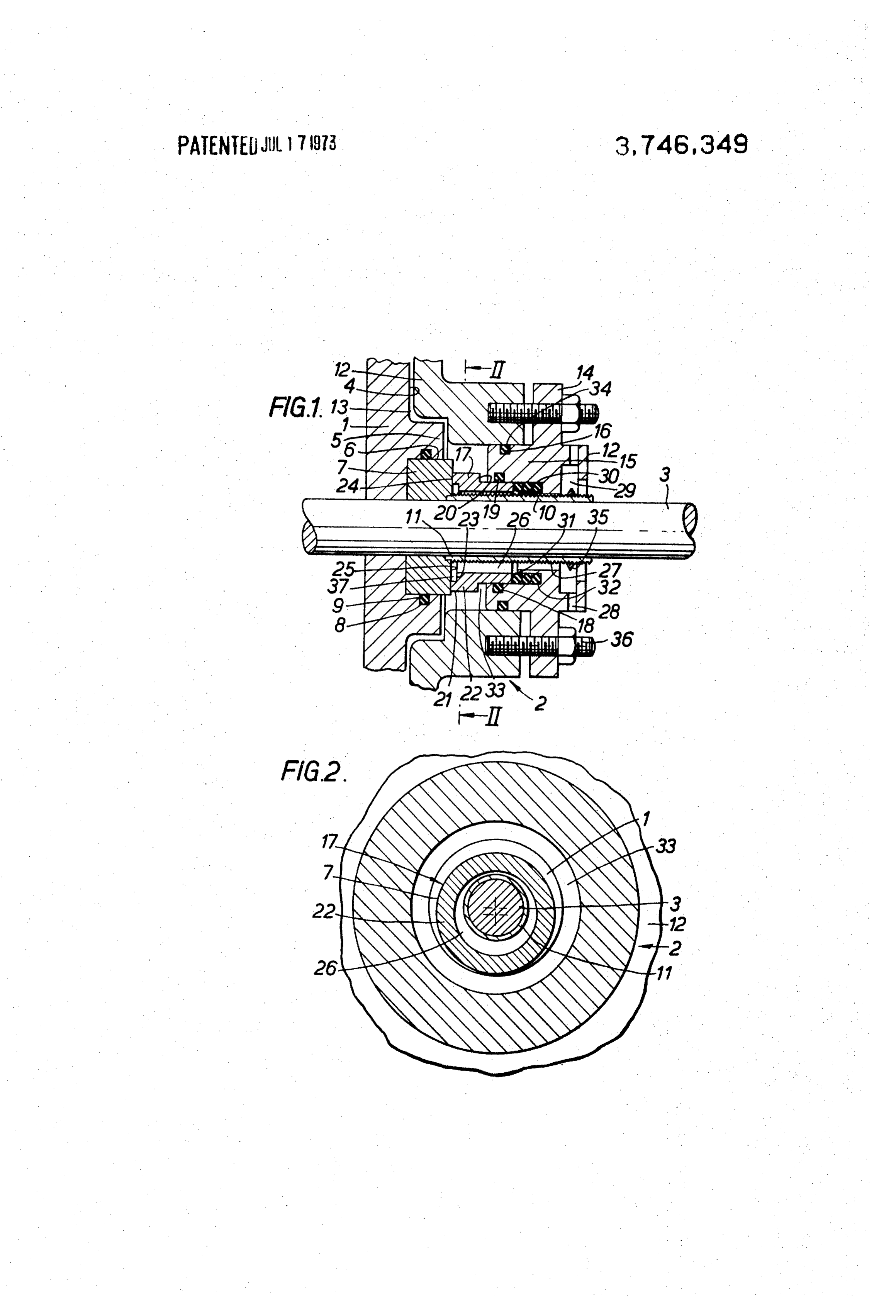
The present invention relates to mechanical seals ative to the other bearing surface the lubrication and and/or thrust bearings and in particular to the lubrica cooling of the bearing surfaces can be effected. tion and cooling thereof. The fluid in which the bearing surfaces are working With mechanical seals it is important to ensure that can act as the lubricant and air can be used as the cool the mating faces are lubricated and prevented from ant, communication being provided with the air outside making actual physical contact by either the liquid the machine of which the bearing surface forms a part. being handled or by other liquid especially introduced 10 In order that the invention may be more readily un for the purpose. A certain amount of physical contact derstood a preferred embodiment thereof is described with consequent production of frictional heat and wear below by way of example only and in conjunction with can take place, particularly when handling liquids of the accompanying drawings, in which: low surface tension, and when this occurs it is neces FIG. 1 is a sectional view through a thrust bearing or sary to have adequate provision for cooling the seal 15 mechanical seal of the present invention; and, faces. The present day use of seal face materials having FIG. 2 is a cross-sectional view along the line A-A extremely poor thermal conductivity makes cooling of FIG. 1.
eyen more necessary. In the particular embodiment shown in FIGS. 1 and The mechanical seal to operate correctly, performs 2 which can be incorporated in a machine or pump, a a similar function to thrust bearing, wherein a flow of 20 rotor 1 is mounted within a housing or stator 2 of a ma lubricant fluid is induced to flow into the inter-face re chine or pump, and liquid or gas is provided within the gion of the bearing and so prevent direct solid contact housing 2 whereby rotation of the rotor 1 causes pump of the face and counter-face. The problem with normal ing or radial movement of the liquid or gas from within thrust bearings is the maintaining of a satisfactory flow the housing 2. The rotor 1 is mounted on a shaft 3, one of cool lubricating fluid between the thrust bearing 25 face 4 namely the rear face of the rotor 1, being pro faces in opposition to the pressure therebetween tend vided with a central circular disc-like extension 5 ex ing to exclude such a flow. One main way of overcom tending therefrom and within which extension 5 there ing this problem in conventional concentric thrust is provided a central recess 6. A thrust disc 7 is bearings is by the provision of radial grooves either mounted within the recess 6 extending from the recess part-way or full-way across one of the thrust bearing 6 and at least one groove 8 is provided within the walls surfaces, but this has the disadvantage of upsetting the of the recess 6 within which a seal 9, such as an O-ring hydro-dynamic flow pattern in the areas of film-flow seal, may be accommodated to prevent flow of fluid be under the thrust pressure and severely limits the loads yond the seal 9 between the wall surface of the recess which may be carried. 6 and the thrust disc 7. The shaft 3 passes centrally of Another known way of overcoming the problem is 35 the thrust disc 7 and the rotor 1 to both of which it is the use of tilting-pad thrust bearings, however the dis fixed, whereby rotation of the rotor 1 and thrust disc 7 advantage of this arrangement is the relatively compli may be effected therewith. The shaft 3 is mounted cated and expensive constructions required. within a sleeve 10 fixedly inserted at its one end 11 It is therefore one object of the present invention to 40 within the thrust disc 7 and rotatable with the shaft 3. overcome these disadvantages by providing adequate A portion 12 of the housing or stator 2 extending to the cooling and lubrication of mechanical seals and/or rear of the rotor 1 has a shape substantially comple thrust bearings whereby a relatively large portion of the mentary with the rearward face 4 of the rotor 1 and contact area of the thrust bearing or sealing surfaces is spaced there from to provide a passage-way 13 be progressively exposed to lubricating fluid to draw in the tween the front face 14 and rear face 4 of the rotor 1 lubricating fluid into the inter-face area continuously 45 to allow the liquid or gas in which the rotor 1 is operat by normal hydro-dynamic forces without the provision ing to flow to contact the rearward face 4 of the rotor of grooves or other flow-disturbing surface irregular 1. An end plate 14 is provided for the housing 2 bolted ities. The provision of this lubrication ensures that the as at 36 or otherwise fixed thereto and through which actual contact area is continuously lubricated by the 50 the shaft 3 and surrounding sleeve 10 extends to be fluid in which they are operating. yond the housing 2 of the machine or pump. The end A further object of the invention is to provide a me plate 14 is provided with an inner annular extension 15 chanical seal or thrust bearing which because of the ab which extends within the housing 2 toward the rotor 1, sence of grooves, tilting areas or other flow-inducing the extension 15 preferably being provided with at least devices, permits the use of optimum conditions of face 55 one groove 16 on its outer surface within which a seal and counter-face surface finishes. 34, such as an O-ring seal may be accommodated to ef According to the present invention a lubricating and fect the sealing of the outer surface of the annular ex cooling apparatus for a mechanical seal and/or thrust tension 15 and the inner surface of the housing or sta bearing comprises a first annular bearing surface tor 2 with which it engages.
mounted in contact with an eccentrically of a second A hollow cylindrical bearing member 17 is provided bearing surface, the eccentricity of the bearing surface 60 engaged with its outer surface in contact with the inner is such that the centres of the two bearing surfaces are surface of the annular extension 15 of the end plate 14, out of line with each other by substantially half the face a groove 18 preferably being provided within the inner width of the narrower face member; one of said bearing surface of the annular extension 16 having a seal 19 surfaces being rotatable relative to the other bearing 65 such as an O-ring seal, accommodated therein to effect surface, means for enabling flow of lubricant to the sealing between the outer cylindrical surface of the thrust bearing surface outwardly of the mutually con bearing member 17 and the inner surface of the annu tacting portions thereof, and means enabling flow of lar extension 15. The outer diameter of the cylindrical
Page 4
bearing member 17 is increased near the end 21 lar thrust bearing surface 24 in contact with the thrust thereof remote from the end plate 14, a shoulder 20 bearing surface 25 of the thrust disc 7. being formed on the outer surface of the cylindrical Due to the space 13 provided between the rear face bearing member 17 by this increased diameter portion 4 of the rotor 1 and the inner surface of the part 12 of 22. The end 21 of the cylindrical bearing member 17 housing 2 the liquid being treated may enter the space has the same outer diameter but smaller inner diameter 33 encircling the cylindrical bearing member 17 and than the increased portion 22 thereof, a further shoul this thus contact the surface of the thrust disc 7 exposed to der 23 being formed on the inner surface therebetween lyingspace 33, namely the portion of thrust surface 25 radially outwardly beyond the outer diameter of to form a pocket or recess 37 which acts as a flow area 10 the cylindrical bearing member 17. The liquid or gas for coolant to enable access right to the mating faces within the space of the bearing surfaces 24, 25 at all times. The end face the inter-face area 33 acts as a lubricant and is drawn into 24 of the bearing member 17 remote from the end plate by normal hydro-dynamic between faces 24, 25 continuously 14 provides an annular bearing surface engageable with forces. With the eccentri the thrust bearing surface 25 of the thrust disc 7. Both 15 cally operating mating thrust bearing surfaces 24, 25 a of these bearing surfaces 24, 25 are uninterrupted, i.e., relatively large portion of the contact area of the thrust devoid of grooves or other flow-disturbing irregular disc 7 is progressively exposed to the lubricating fluid. ities, to thus ensure the establishing of a stable hydro Thus film of lubricant fluid is induced to flow into the inter-face region of the thrust bearing surfaces 24, 25 dynamic film between the face 24, 25.
The sleeve 10 on the shaft 3 is provided within the cy 20 and so prevent direct solid contact of the mating thrust lindrical bearing member 17 spaced therefrom, the bearing tinually surfaces 24, 25. Thus it is ensured that a con changing area of one of the mating faces of the space 26 so formed being of eccentric annular cross thrust bearing surfaces is at all times exposed to the section and this space 26 is in direct communication fluid being handled by the pump or machine. with the atmosphere outside the casing or stator 2 via an outlet passage-way or bore 27 provided within the 25 faces 24, 25 in particular when thecooling In order to effect simultaneous of these sur material used in the end plate 14 and outlet ports 28 within the plate. The thrust disc 7 and cylindrical bearing member 17 is of outlet passageway 27 has an enlarged portion forming poor thermal conductivity, direct communication be an annular chamber 29, the outlet ports 28 extending tween the air of the atmosphere outside the machine radially from this chamber. with the surface 25 of the thrust disc 7 within the cylin The cylindrical bearing member 17 is held with its 30 drical bearing member 17 via the passageways 26, 27 annular bearing surface 24 in contact with the thrust encircling the sleeve 10 and bores 28 within the end bearing surface 25 of the thrust disc 7 by biasing means plate 14 can be effected. In this way a continually engaging against its outer annular end 31, such as a se changing area of the mating faces of the thrust bearing ries of O-rings 30 made of an elastomer material and surfaces 24, 25 is at all times exposed to the air space which provides the necessary flexibility to ensure con 35 on the outside of the pump or machine. tinuous contact of these mating faces. The O-rings 30 If desired chilled air could be fed into passageway 27 are accommodated in a suitable recess 32 provided in via one of the outlets 28 and removed from the other. the end plate 14 and against which they bear. This is of particular advantage if the liquid being han The annular bearing surface 24 engages eccentrically dled by the machine is not allowed to come into con of the thrust bearing surface 25 of the thrust disc 7 at 40 tact with an alternative coolant such as water which tached to the rotor 1 and is of such internal and outer could be fed into the space within the cylindrical bear diameter as to lie within the outer diameter of the ing instead of air. Cooling water could be fed in thrust disc 7. through one of the ports 28 in the end plate 14 into the The stator or casing 2 encircling the annular exten annular chamber 29 where it may pass through the sion 15 of end plate 14 and the cylindrical bearing 45 outer passageway 27 encircling the sleeve and shaft and member 17 provides an annular space 33 encircling the then come into contact with the thrust bearing surfaces cylindrical bearing member 17 as shown in FIG. 1. The 24,25 and cool and to some extent lubricate the cylin space 33 is in communication with the space 13 be drical bearing member 17 and likewise the thrust disc tween the rear face 4 of the rotor 1 and the bearing sur 50 7. The water can be removed via the other outlet port face 25 of the thrust disc 7. The proportion and loca 28 provided in the end plate 14. As the cooling water tion of the area of surface 25 exposed to this space will or liquid coolant flows back toward the end plate 14 it vary according to the relative position of the annular is preferably pushed outwardly towards the outlet port eccentric bearing surface 24 of the cylindrical bearing 28 by a so called "slinger" 35 encircling the sleeve 10 member 17, with the thrust bearing surface 25 of the 55 within the enlarged annular chamber 29 by virtue of thrust disc 7. centrifugal force. This "slinger'35 is in the form of an As the shaft 3 is rotated, the rotor 1 and thrust disc annulus or ring preferably with tapered cross-section. 7 attached thereto are rotated therewith, the rotor act The sleeve 10 is preferably of suitable corrosion ing upon the liquid or gas being treated within the hous resisting material such as plastics material for example, ing 2, to rotate this fluid as required by the machine or 60 when the liquid or gas being treated is corrosive and is pump in which it is installed. At the same time the rota provided on its outer surface with a return screw tion of shaft 3 will cause relative rotational movement threaded 34 impressed therein so that the cooling liq between the thrust bearing surfaces 24, 25 whereby the uid fed into the space 26 surrounding the sleeve 10 is thrust bearing surface 25 of the thrust disc 7 will rotate assisted to move axially into the region adjacent the relative to the substantially stationary annular thrust 65 thrust bearing surfaces 24, 25.
bearing surface 24 of the cylindrical thrust member 17. By suitably proportioning the thrust bearing surfaces The biasing means 30 bearing against the outer end 31 24, 25 and by mounting the rotary thrust disc 7 and sta of the cylindrical thrust member 17 will hold the annu tionary cylindrical thrust member 17 eccentric to each.
Page 5
other by a predetermined relative amount it is possible cal bearing member substantially stationary relative to to achieve the desirable operating features, namely the the thrust disc and in contact with the thrust disc during provision of maximum sealing between the liquid being rotation of the shaft.
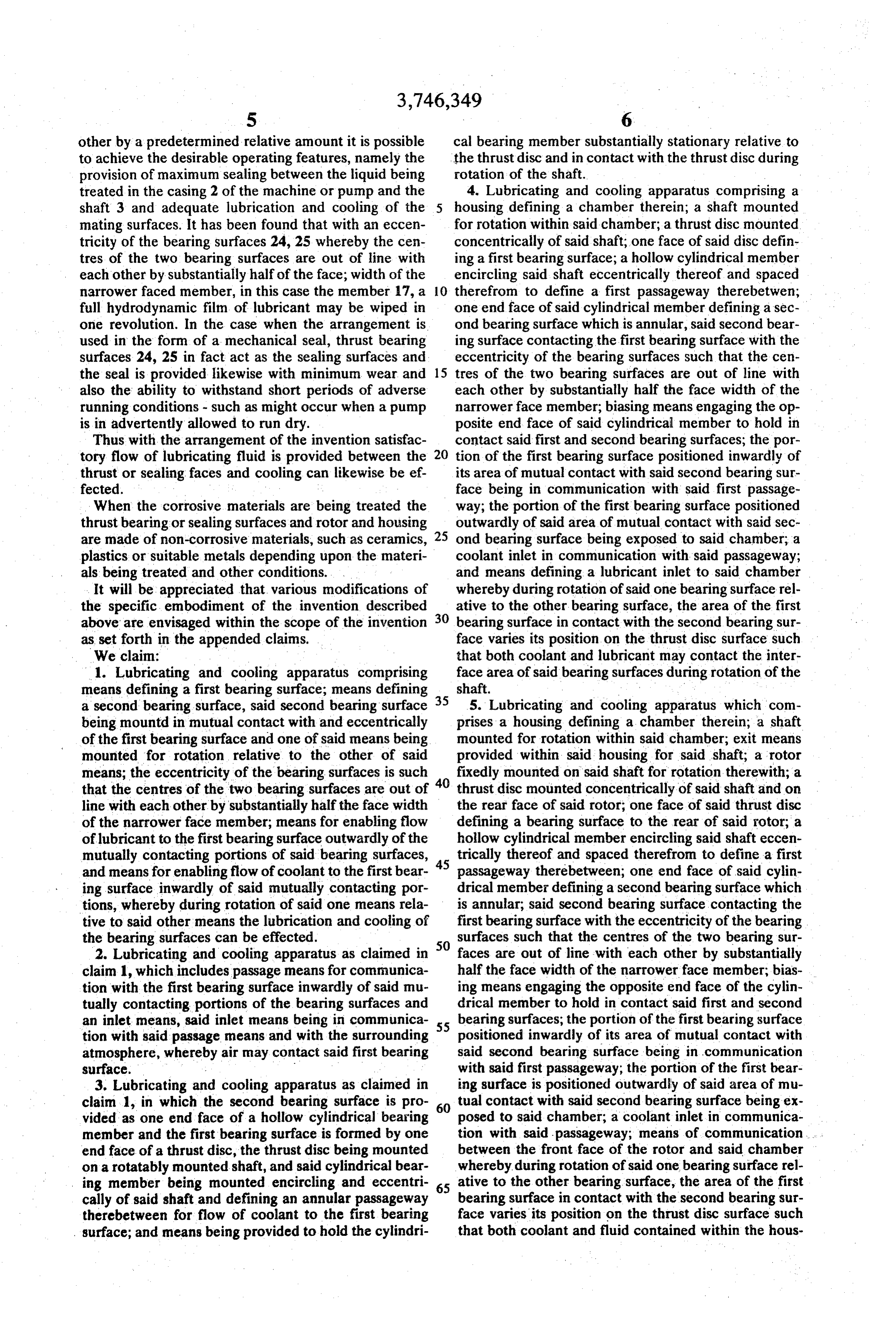
treated in the casing 2 of the machine or pump and the 4. Lubricating and cooling apparatus comprising a shaft 3 and adequate lubrication and cooling of the housing defining a chamber therein; a shaft mounted mating surfaces. It has been found that with an eccen for rotation within said chamber; a thrust disc mounted tricity of the bearing surfaces 24, 25 whereby the cen concentrically of said shaft; one face of said disc defin tres of the two bearing surfaces are out of line with ing a first bearing surface; a hollow cylindrical member each other by substantially half of the face; width of theencircling said shaft eccentrically thereof and spaced narrower faced member, in this case the member 17, a 10 therefrom to define a first passageway therebetwen; full hydrodynamic film of lubricant may be wiped in one end face of said cylindrical member defining a sec one revolution. In the case when the arrangement is ond bearing surface which is annular, said second bear used in the form of a mechanical seal, thrust bearing ing surface contacting the first bearing surface with the surfaces 24, 25 in fact act as the sealing surfaces and eccentricity of the bearing surfaces such that the cen the seal is provided likewise with minimum wear and 15 tres of the two bearing surfaces are out of line with also the ability to withstand short periods of adverse each other by substantially half the face width of the running conditions - such as might occur when a pump narrowerface member; biasing means engaging the op is in advertently allowed to run dry. posite end face of said cylindrical member to hold in Thus with the arrangement of the invention satisfac contact said first and second bearing surfaces; the por tory flow of lubricating fluid is provided between the 20 tion of the first bearing surface positioned inwardly of thrust or sealing faces and cooling can likewise beef its area of mutual contact with said second bearing sur fected. face being in communication with said first passage When the corrosive materials are being treated the way; the portion of the first bearing surface positioned thrust bearing or sealing surfaces and rotor and housing outwardly of said area of mutual contact with said sec are made of non-corrosive materials, such as ceramics, 25 ond bearing surface being exposed to said chamber; a plastics or suitable metals depending upon the materi coolant inlet in communication with said passageway; als being treated and other conditions. and means defining a lubricant inlet to said chamber It will be appreciated that various modifications of whereby during rotation of said one bearing surface rel the specific embodiment of the invention described 30 ative to the other bearing surface, the area of the first above are envisaged within the scope of the invention bearing surface in contact with the second bearing sur as set forth in the appended claims. face varies its position on the thrust disc surface such We claim: that both coolant and lubricant may contact the inter 1. Lubricating and cooling apparatus comprising face area of said bearing surfaces during rotation of the means defining a first bearing surface; means defining 35 shaft.
a second bearing surface, said second bearing surface 5. Lubricating and cooling apparatus which com being mountd in mutual contact with and eccentrically prises a housing defining a chamber therein; a shaft of the first bearing surface and one of said means being mounted for rotation within said chamber; exit means mounted for rotation relative to the other of said provided within said housing for said shaft; a rotor means; the eccentricity of the bearing surfaces is such 40 fixedly mounted on said shaft for rotation therewith; a that the centres of the two bearing surfaces are out of thrust disc mounted concentrically of said shaft and on line with each other by substantially half the face width the rear face of said rotor; one face of said thrust disc of the narrower face member; means for enabling flow defining a bearing surface to the rear of said rotor; a of lubricant to the first bearing surface outwardly of the hollow cylindrical member encircling said shaft eccen mutually contacting portions of said bearing surfaces, 45 trically thereof and spaced therefrom to define a first and means for enabling flow of coolant to the first bear passageway therebetween; one end face of said cylin ing surface inwardly of said mutually contacting por drical member defining a second bearing surface which tions, whereby during rotation of said one means rela is annular, said second bearing surface contacting the tive to said other means the lubrication and cooling of first bearing surface with the eccentricity of the bearing the bearing surfaces can be effected. surfaces such that the centres of the two bearing sur 2. Lubricating and cooling apparatus as claimed in 50 faces are out of line with each other by substantially claim 1, which includes passage means for communica half the face width of the narrower face member; bias tion with the first bearing surface inwardly of said mu ing means engaging the opposite end face of the cylin tually contacting portions of the bearing surfaces and drical member to hold in contact said first and second an inlet means, said inlet means being in communica 55 bearing surfaces; the portion of the first bearing surface tion with said passage means and with the surrounding positioned inwardly of its area of mutual contact with atmosphere, whereby air may contact said first bearing said second bearing surface being in communication surface. - with said first passageway; the portion of the first bear 3. Lubricating and cooling apparatus as claimed in ing surface is positioned outwardly of said area of mu claim 1, in which the second bearing surface is pro 60 tual contact with said second bearing surface being ex vided as one end face of a hollow cylindrical bearing posed to said chamber; a coolant inlet in communica member and the first bearing surface is formed by one tion with said passageway; means of communication end face of a thrust disc, the thrust disc being mountedbetween the front face of the rotor and said chamber on a rotatably mounted shaft, and said cylindrical bear whereby during rotation of said one bearing surface rel ing member being mounted encircling and eccentri 65 ative to the other bearing surface, the area of the first cally of said shaft and defining an annular passageway bearing surface in contact with the second bearing sur therebetween for flow of coolant to the first bearing face varies its position on the thrust disc surface such surface; and means being provided to hold the cylindri that both coolant and fluid contained within the hous
Page 6
ing and treated by rotation of said front face of the 10. A pump which comprises a housing defining a rotor may cool and lubricate the inter-face area of said chamber therein; a shaft passing into said housing for bearing surfaces during rotation of the shaft, said bear rotation therein; a rotor fixedly mounted on said shaft ing surfaces simultaneously providing a mechanical for rotation therewith; fluid means provided within said seal between said chamber and said exit means pro housing; exit means within said housing for said fluid; vided in the housing for said shaft. said rotor having a front face and a rear face; said front 6. Lubricating and cooling apparatus as claimed in face being effective to act upon the fluid within said claim 4 in which means are provided within the housing housing to pump said fluid from said housing through defining a recess within which a series of O-ring seals said exit means; the rear face of said rotor having a are housed; said O-ring seals engaging said opposite 10 thrust disc mounted thereon, said thrust disc being si end face of the cylindrical member to hold in contact multaneously mounted concentrically of said shaft; the said first and second bearing surface and simulta neously prevents substantial rotational movement of face a of said thrust disc remote from said rotor defining first bearing surface; a hollow cylinder mounted ec the cylindrical member relative to the thrust disc.
7. Lubricating and cooling apparatus as claimed in 15 an annular ofpassageway centrically said shaft and spaced therefrom to define therebetween; one end face of claim 4 in which the hollow cylindrical member is pro said hollow cylinder defining a second bearing surface vided with a stepped inner diameter in its end portion which is annular; the eccentricity of the bearing sur adjacent the thrust disc to define a pocket or recess in faces is such that the centres of the two bearing sur contact with the thrust disc to act as a flow area for coolant flowing to the first bearing surface. 20 faces are out of line with each other by substantially 8. Lubricating and cooling apparatus as claimed in ing half the face width of the narrower face member; bias claim 4 in which a sleeve is provided encircling and means holding the second bearing surface in con fixedly connected to the shaft and provided with a tact with the first bearing surface whereby said annular screw thread on its outer surface so formed as to tend passageway is in contact with the portion of the face of to return from said first bearing surface coolant flowing 25 the first disc positioned inwardly of the interface of said within said first passageway. bearing surface; means defining a coolant inlet in said 9. Lubricating and cooling apparatus as claimed in housing in communication with said annular passage claim 4, which includes means defining an inlet for way; the rear face of said rotor and said housing defin coolant in said housing; means defining an outlet for ing therebetween a passageway for fluid to the rear face coolant in said housing; means defining an annular pas 30 of said housing and to said one face of the thrust disc; sageway surrounding said shaft and communicating whereby during pumping action of said rotor a rela said inlet means and outlet means with said first pas tively large portion of the bearing surfaces are progres sageway; slinger means encircling and fixedly mounted sively exposed to coolant and to said fluid whereby the on said shaft to rotate therewith within said annular inter-face areas of the bearing surfaces are continu passageway to feed returning coolant to said outlet 35 ously cooled by coolant: and lubricated by said fluid. eas.
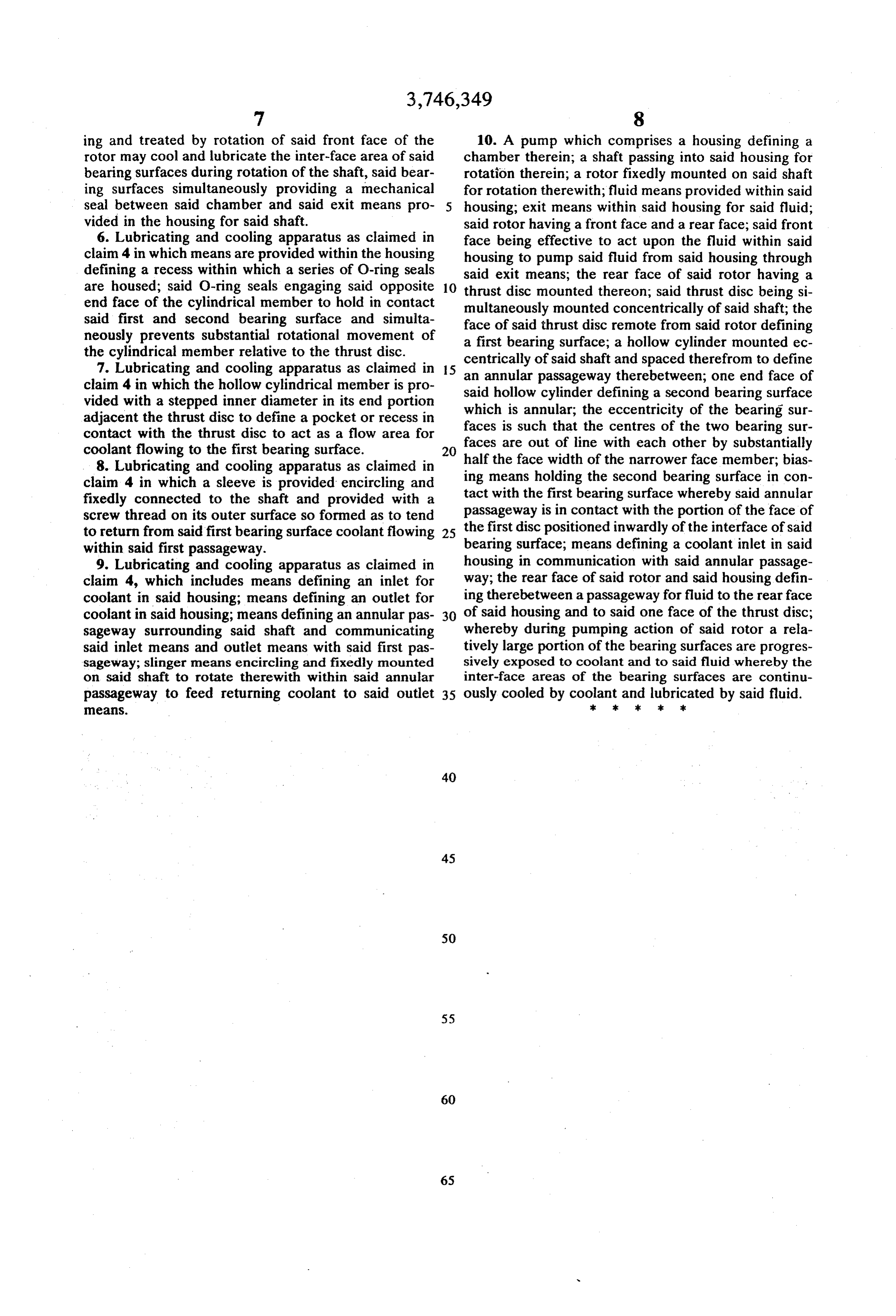
Provenance
- Collection
- Cited prior art
- Original PDF
- patentimages.storage.googleapis.com →
- Filed
- 1970-08-26
- Pages
- 6
- Method
- pdftotext (the PDF's own text layer) + pdftoppm 300dpi page scans
- Source
- Google Patents bibliographic record
- Granted
- 1973-07-17
- Inventors
- J Smale; F Robson
- Transcribed from
- patentimages.storage.googleapis.com →