patent · US4866321
Brushless electrical machine for use as motor or generator
12 September 1989
Page 1 — bibliographic record
United States Patent (19) 11 Patent Number: 4,866,321 Blanchard et al. 45 Date of Patent: Sep. 12, 1989 (54) BRUSHLESSELECTRICAL MACHINE FOR 4,315, 178 2/1982 Ban ................... ... 310/268 X USE AS MOTOR OR GENERATOR 4,336,475 6/1982 Morinaga et al. ... 310/198 4,357,550 1 1/1982 Miller ............... 310/43 (75) Inventors: Hubert J. Blanchard; Cornelius J. 4,358,693 11/1982 Palmer et al. ......................... 310/46 Fruge, both of Mamou, La. 4,477,745 10/1984 Lux ............... ... 310/268 X 4,605,874 8/1986 Whiteley ... 31.0/268 (73) Assignee: William C. Lamb, Lafayette, La. 4,634,912 1/1987 Heyraud.... ... 30/268 21 Appl. No.: 714,801 FOREIGN PATENT DOCUMENTS 22 Filed: Mar. 26, 1985 1080677 4/1960 Fed. Rep. of Germany ...... 310/156 (51) Int, C.'...................... H02K 21/12; HO2K 19/16 2006542 5/1979 United Kingdom ................ 310/112 52) U.S. C. .................................... 310/112; 310/126; OTHER PUBLICATIONS
(58) Field of Search ................. 310/43, 156, 268, 112, IEEE Transactions on Power Apparatus and Systems, 310/114, 124, 126 vol. PAS-99, No. 6, Nov./Dec. 1980.
References Cited
IEEE Transaction on Power Apparatus and Systems, (56) vol. PAS-101, No. 4, Apr. 1982.
Primary Examiner-Patrick R. Salce 2,437,142 3/1948 Welch ................................. 172/275 Assistant Examiner-Judson H. Jones : 3. Egan - -- - - - - - - - - as a 38 Attorney, Agent, or Firm-Arnold, White & Durkee 3,354,332 11/1967 Bonnefoy ............................ 310/268 57 ABSTRACT 3,543,066 11/1970 French ................................ 310/186 57 3,665,227 5/1972 Busch .................................... 310/46 A brushless electrical machine has a stator assembly 3,670,189 6/1972 Monroe ................................. 310/46 with spaced coils and a rotor assembly with spaced 3,686,521 8/ E. EBaudot 3. permanent magnets and with axial air gaps between the 3. 7.4 Ain't a 3103: assemblies. The magnets define rotatable flux-produc 39;257. 11/1975 Whiteley ............................. 310/156 ing modules and the coils are in positions adjacent to the 3,979,619 9/1976 Whiteley ............................. 310/268 3,999,092 12/1976 Whiteley ............................. 310/156 paths of travel of the magnets. The machine can be operated as a low speed, high torque motor or as a low 4,127,785 11/1978 Noguchi................................ 310/89 speed, high power output generator with output char 3. 2/1980 Oney ................................... 9/2 acteristics proportional to the number of axially inter E. As yet al. .................. 3A leaved stator and rotor assemblies.
4,297,604 10/1981 Tawse. . 31.0/268 X 4,315,177 2/1982 Ban ................................. 310/268 X 16 Claims, 4 Drawing Sheets
nate
FEREP
ZNZ
EF- IES
Page 2
Drawing sheet — no readable text.
Page 3
Drawing sheet — no readable text.
Page 4
Drawing sheet — no readable text.
Page 5
Drawing sheet — no readable text.
Page 6
permanent magnet discs. There are axial air gaps be
BRUSHLESSELECTRICAL MACHINE FOR USE tween the stators and the rotors. The machine is modu AS MOTOR OR GENERATOR lar in construction in that it is an assembly of stators held together by rods or equivalent means. The ma
This invention pertains generally to an axial air gap, 5 chine is also low in mass in that the rotors and stators brushless electric machine having alternate stators and are both made of strong, lightweight, synthetic, dielec rotors. Each stator has a plurality of bobbin-type coils tric materials-preferably polycarbonate resins. Both distributed about its periphery. Each rotor has a plural the stators and the rotors are basically disk-like in ap ity of permanent magnet discs about its periphery which pearance.
rotate past the coils of adjacent stators. The machines O The bobbin coils and the permanent magnets are may be used as motors or generators. They are espe spaced around the peripheries of the stators and rotors, cially characterized by their light weight and structural respectively. Rotation of the rotors causes the magnets flexibility. to pass by the coils in rapid sequence. The number of BACKGROUND OF THE INVENTION coils in relation to the number of magnets should be in 15 a five-to-eight ratio. The magnets in all of the rotors
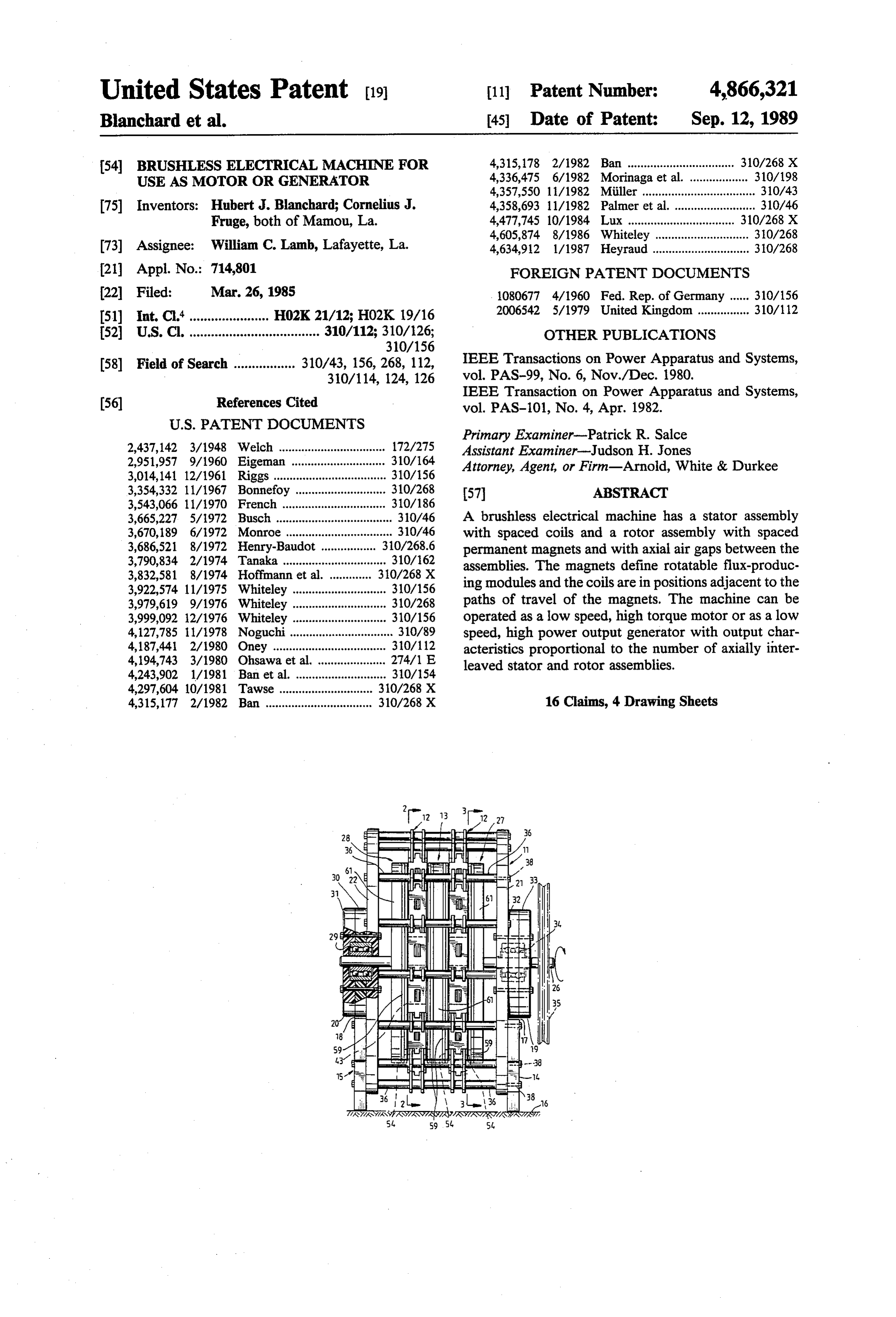
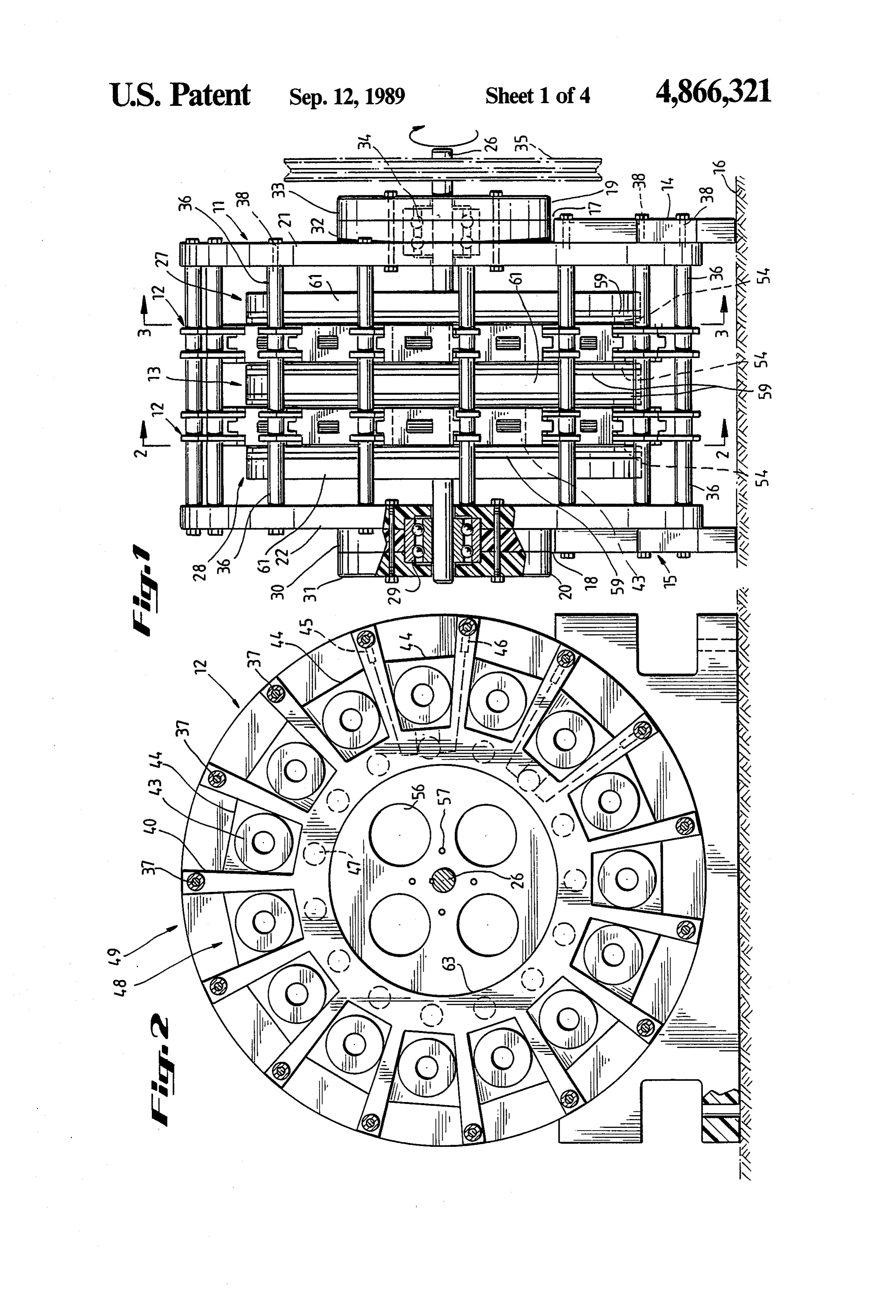
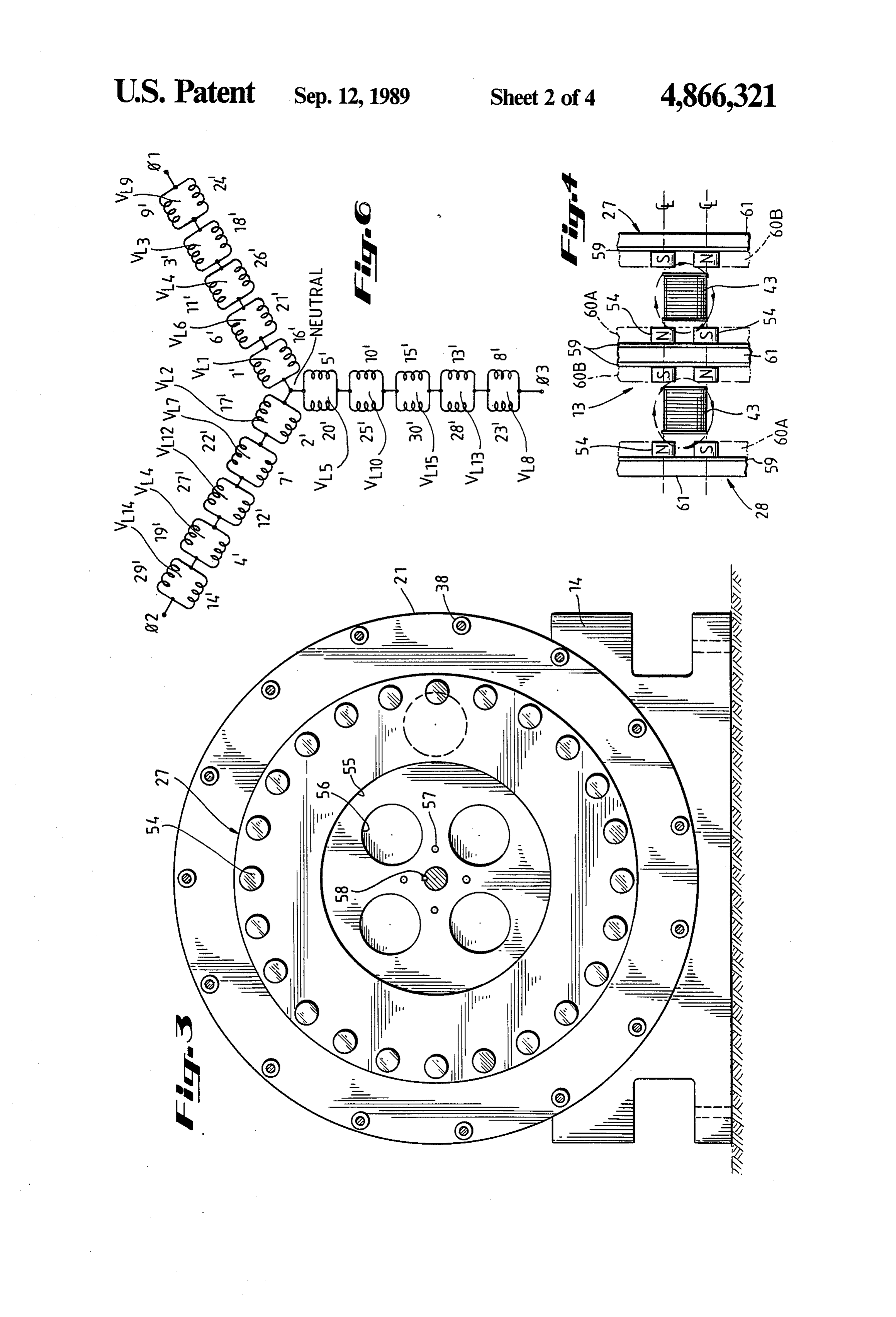
An industrial need exists for a low cost, high torque should be in axial alignment as should be the coils in all to-weight ratio, brushless electrical motor capable of of the stators. The coils are mounted in the stators in a operating at relatively low speeds, typically under 800 manner to be accessed and replaced. rpm. Such motors, when operated as vehicle traction IN THE DRAWINGS motors for example, can eliminate the need for both mechanical transmissions and differentials. The motors FIG. 1 is a side view, in partial section, of an embodi also have application in servo systems used in robotics ment of the invention with two sets of stationary stator and other motion control devices which are gear lim windings, two end-piece rotating magnetic rotors and ited in design. one double-sided magnetic rotor; A need also exists for a low cost, high power electri 25 FIG. 2 is a section taken along section lines 2-2 of cal generator capable of operating at low speeds, typi FIG. 1, illustrating the layout of the bobbin coils; cally under 300 rpm. Such generators may be directly FIG. 3 is a section taken along section lines 3-3 of wind-driven by large propellers; they may also be di FIG. 1 illustrating the layout of the magnetic rotors and rectly driven by water wheels or turbines in streams or their rotating magnets;
dams. It is also contemplated these generators will be FIG. 4 is a partial section of the inter-leaved bobbin able to greatly reduce the need for mechanical gearing, coils and permanent magnets illustrating the flow of which in typical wind power generation systems can magnetic flux lines;
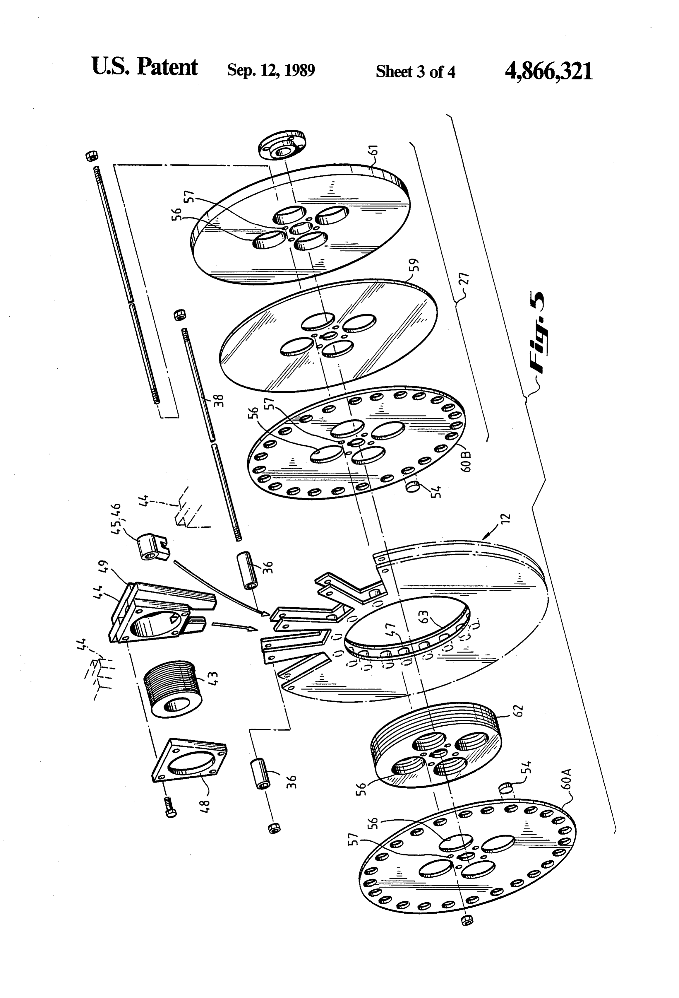
cost more than the generator. Some of these require FIG. 5 is an exploded view of a stator assembly be high efficiency conversion of motive power to electri tween an end-piece rotor and part of another rotor; cal power. Rather, the initial cost and the cost of main 35 FIG. 6 is a winding connection diagram for a three tenance become the more important factors. phase machine.
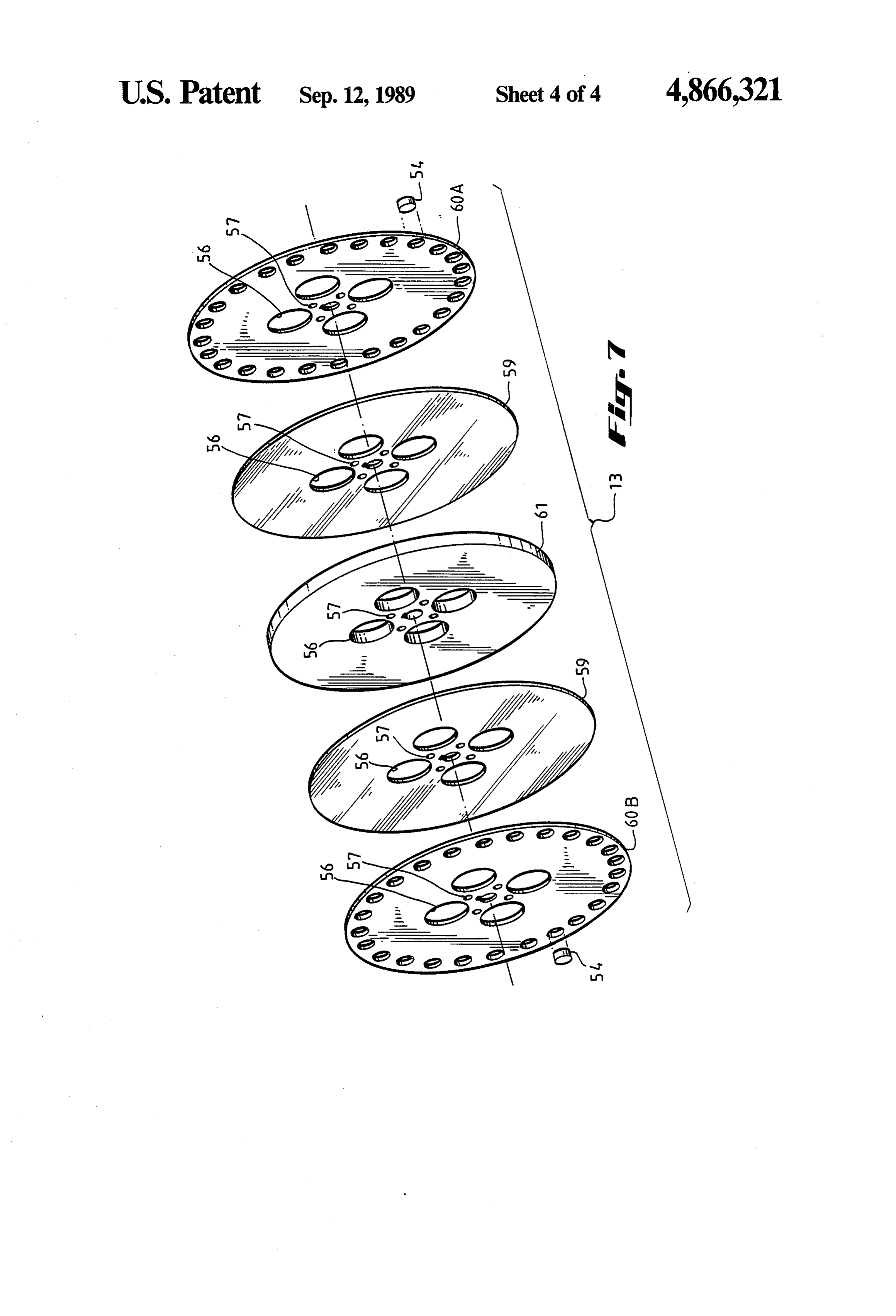
Brushless design of motors requires that stator wind FIG. 7 is an exploded view of a double-sided central ings be mounted in a stationary fashion and that rotors rotor 13.
be fastened to a shaft for rotary motion. In the past, the A preferred embodiment of the invention is broadly stator assembly of a brushless electrical motor has been denoted by the numeral 11 in FIG. 1. The machine mounted inside a housing or yoke. The housing or yoke shown there can form either a motor or a generator; serves no energy conversion function, but it maintains however, for purposes of present illustration, it will be stator alignment and concentricity with the rotor shaft. referred to as a motor.
Elimination of most of the housing would help to realize The machine in FIG. 1 is simple in that it comprises increased torque-to-weight ratios. 45 two stators and three rotors, one of the rotors being a Magnets deliver usable flux in relation to the operat double-sided rotor. It will be noted, however, that ing pointBD of the magnets. Magnetic circuits that have larger machines can be readily made by adding addi flux paths which are always aiding in series with the tional stators and interposing them between additional individual magnet polarities provide a higher operating double-sided magnetic rotors. The addition of an addi point BD than circuits which cause the magnets to be in 50 tional stator and a double-sided magnetic rotor may be opposition or which have magnetic flux paths with high referred to as the addition of a stack. The addition of reluctance. Further, the greater the flux density per unit stacks results in a machine which increases in length mass of magnet, the greater the torque-to-weight ratio end-to-end. The addition of stacks also serves to in will be for the entire machine, other parameters remain crease the power generated in a generator and the ing the same. 55 horsepower rating in a motor. SUMMARY OF THE INVENTION Motor 11 comprises end supports 14 and 15 with flat bottoms which bear on surface 16. The tops of supports
It is a general object of the invention to provide an 14 and 15 have semicircular recesses to fit against the electrical machine which can serve as a motor or a shaft-bearing housings 19 and 20, respectively. Housing generator. The machine is characterized by high tor 19 comprises bearing support members 32 and 33, and que/mass ratios, simple but rugged construction, and housing 20 comprises bearing support members 30 and ease of repair. The machine is versatile in that it is easy 31.
to assemble and disassemble, and its capacity is readily End supports 14 and 15 are bolted to motor housing changed. It can operate at relatively low speeds, and it end members 21 and 22. Motor housing end members 21 is especially suited for use in remote areas. 65 and 22 are preferably circular in configuration and of The present machine is brushless and has a stator the same diameter as stators 12. Motor housing end which has a plurality of coils wound on bobbin-like members 21 and 22 are also preferably constructed of cores. The machine also has a rotor with a plurality of polycarbonate plastic; however, any material having
Page 7
structural rigidity and dielectric properties similar to or tionally each bobbin insertion piece is restrained be greater than polycarbonates may also be used. One such tween two wedge-shaped arms. Thus, bobbin insertion type of polycarbonate material is Lexan manufactured piece 44 in FIG. 2 is locked between arms 45 and 46. by General Electric. Arms 46 are held in place by through-bolts 38. Addi Rotor shaft 26 penetrates the entire machine assembly tionally, bobbin 43 and bobbin insertion piece 44 are 11, including motor housing end members 21 and 22, restrained in the longitudinal direction by stator walls stationary stator members 12, end piece rotating mag 48 and 49 (illustrated in FIG. 5). netic rotors 27 and 28 and double-sided magnetic rotor Again referring to FIG. 2, fifteen bobbin coil mem member 13. Shaft 26 is supported at one end by bearing bers 43 are circumferentially disposed about stator 12. It 29 enclosed in bearing support members 30 and 31. In a 10 can be appreciated from the foregoing disclosure that similar manner bearing support members 32 and 33 for larger machines with larger diameter stators 12, support bearing 34. Bearing support members 32 and 33 more bobbin coil members 43 may be accommodated. are circular in the preferred embodiment; however, this The modular nature of the present invention enables configuration is not critical. Bearing support members the ready removal and replacement of bobbin coils 43 30, 31, 32 and 33 are preferably made of polycarbonate 15 without complete disassembly of the machine. This is plastic because of its strength and light weight; how accomplished by removal of the two through-bolts 38 ever, any material with similar structural and dielectric adjacent the bobbin insertion piece 44 of the bobbin coil properties may be utilized. Bearing support members 32 43 to be replaced. Once the through-bolts 38 have been and 33 are bolted to motor housing end member 21. In removed, the bobbin insertion piece blocking spacers 45 a similar manner bearing support members 30 and 31 are 20 and 46 are withdrawn radially. Once the bobbin inser bolted to motor housing end-member 22. tion piece blocking spacers 45 and 46 have been re The shaft 26 is rigidly connected to end rotors 27 and moved, the bobbin insertion piece 44 may be withdraw 28 and double-sided central rotor 13. Shaft 26 is free to n-also in a radial direction. After the bobbin insertion rotate relative to stators 12. This physical arrangement piece 44 has been withdrawn from the machine, the in a motor configuration permits the rotors 27, 28 and 13 25 bobbin coil 43 may be removed in a longitudinal direc to deliver rotational energy to shaft 26 with a transla tion. A new bobbin coil member 43 may then be in tion of this energy to pulley 35 which is conveniently serted, and the above-described steps repeated in re belt-coupled to the load to be driven. Alternatively, verse order. Thus, a single bobbin coil may be replaced pulley 35 may be removed and shaft 26 direct coupled without total disassembly of the machine. to a load, either directly or through a transmission. 30 Referring next to FIG. 3, a sectional view of FIG. 1 In a generator configuration, power is delivered to taken along section lines 3-3 is illustrated. For refer shaft 26 either directly or as through pulley 35. The ence purposes, support member 14 is shown in the back rotating forces are consequently delivered to end rotors ground as well as motor housing end member 21. Also 27 and 28 and double-sided magnetic rotor members 13. shown for reference purposes are through-bolts 38 and This rotating force results in a rotating magnetic field 35 bolt holes 37 circumferentially spaced about housing which is transferred by transformer action to stators 12. end member 21. End rotor 27 is illustrated with rare The variations in magnetic flux in the coils of stators 12 earth magnets 54 circumferentially spaced about the result in electrical energy delivered to the generator rotor. Also illustrated is rotor spacer 55. Rotor spacer terminals. 55 has a plurality of longitudinal holes 56 which aid in Referring to FIG. 1, end rotors 27 and 28 and double the ventilation of the machine as well as minimize its sided magnetic rotor member 13 are circular in configu weight. Rotor spacer 55 has a plurality of assembly ration with an outside diameter less than motor housing holes 57 as well as a shaft hole'58 to accommodate shaft end members 21 and 22 and stators 12. The outside 26 which penetrates the machine longitudinally. Rotor diameters of motor housing end members 21 and 22 are spacer 55 is preferably constructed of polycarbonate the same as the outside diameter of stators 12. The 45 resins; however, any material with similar dielectric and smaller diameters of the rotors 27, 28 and 13 permit the structural properties may be used. shaft 26 and rotating structures to rotate without inter The rare earth magnets 54 are circular in configura fering with spacers 36. tion. This configuration is less expensive to manufacture Spacers 36 are disposed about the circumference of and produces a sharper flux change in the bobbin coils the motor 11 in a circular configuration about end hous 50 43, thereby producing more power for a generator and ing members 21 and 22 and stators 12. Referring to FIG. delivering more torque in a motor. 2, the positioning of spacers 36 around the circumfer Referring to FIG. 3, twenty-four magnets are illus ence of stator 12 is designated by accurately spaced trated about the circumference of end piece rotor 27. spacer holes 37. Each spacer member 36 is a hollow Adjacent magnets on the same side of any given rotor tubular member designed to accommodate through 55 are opposite in polarity. Similarly, magnets which are in bolts 38. Through-bolts 38 are parallel to the axis of the axial alignment with one another, and which are back machine (parallel to shaft 26), and are circumferentially to-back on the same rotor or face one another on adja disposed about housing end members 21 and 22 and cent rotors, are also opposite in polarity. The machine stator 12. Through-bolts 38 in essence hold the machine disclosed herein is designed to operate at speeds from together. Additionally, through-bolts 38 hold spacers 300 RPM to 800 RPM. The machine's synchronous 36 in position by restraining any displacement in a radial speed at 60 Hertz is 300 RPM for the 24 pole machine or longitudinal direction. described herein. However, when operated as a genera Referring to FIG. 2, an elevational view of stator 12 tor, the machine generates 60 Hz electric power at 300 is illustrated. This view is taken along section lines 2-2 RPM.
of FIG. 1. Fifteen bobbin coils 43 are longitudinally 65 It has been discovered that the preferable coil to inserted into separate bobbin insertion pieces 44. Each magnet ratio is five to eight (5:8). This ratio has been bobbin insertion piece 44 is wedge-shaped and is re found to be more efficient and balanced than other strained in its proper axial position by a post 47. Addi ratios. Specific examples of satisfactory machine de
Page 8
signs include coil to magnet ratios of 5 to 8, 15 to 24, 30 Referring next to FIG. 5, an exploded view of a sec to 48, 45 to 72 and so on. The ratio of 15 to 24 in the tion of the machine is illustrated. End rotor 27 con prototype machine is deemed a limiting configuration prises an assembly of magnet embed plate 60B, soft steel only by the diameter of the machine. Thus, as the ma plate 59 and spacer 55. Magnet embed plate 60 and chine diameter is increased the number of bobbin coils spacer 55 are constructed of polycarbonate plastic in and magnets may be increased. Similarly as the diame the preferred embodiment. The purpose of spacer 55 is ter of the machine is decreased, the number of bobbin to increase the spacing between steel plate 59 and other coils 43 and magnets 54 may be decreased. However, ferrous materials, thereby minimizing interference with the ratio of five to eight should be maintained. the magnetic flux linkages. The soft steel plate 59, The object of a five to eight, coil to magnet ratio is to 10 which serves as a return path for the magnetic flux permit an equal number of coils on each one of three 60B linkages, is sandwiched between magnet embed plate electrical phases to "fire' at the same time. The electri the rare and spacer 55. The magnet embed plate 60 retains cal “firing” of the coils at the same time is important to may be epoxiedearth magnets 54. The rare earth magnets 54 reduce the vibration of the machine and to have equally 15 or glued into the plate 60. Rotor 28 in displaced voltage vectors. It is also important that the rotating magnetic rotorin27;
FIG. 1 is constructed a similar manner as end piece physical construction of the machine be such that the and magnet embed plate 60 however, the steel plate 59 magnets 54 are equally spaced about the circumference side of spacer member 55 in order to haveonthethemagnet are located opposite
of the end rotors 27 and 28 as well as the double sided rotor 13. In a similar manner, it is important that bobbin embedded in embed plate 60 adjacent the bobbin coils
coil members 43 be equally spaced about the circumfer A double-sided magnetic rotor member 13 is con ence of stators 12.
structed similar to end piece rotor 27; however, a soft
Referring next to FIG. 4, the arrangement of the rare steel plate 59 is located on either side and adjacent to earth magnets 54 with respect to the bobbin coils 43 is spacer member 55. In a similar manner a magnetic further illustrated. As shown there, the coils 43 of two 25 embed plate adjacent stators are being swept by magnets 54 of three the soft steel60plate is located on either side and adjacent to 59. This configuration results in a rotors 27, 28 and 13. The magnetic flux lines flow be double-sided magnetic rotor, thus enabling the rare tween the north and south magnets 54 and utilize soft earth magnets 54 to be positioned adjacent to the sta steel plates 59 on the axially outer surfaces of rotors 27 tionary stator members 12 and the bobbin coils 43 on and 28. In a similar manner a soft steel plate 59 is sand 30 each stationary stator member 12. wiched in between the two sides of double-sided rotor Ventilation holes 56 are found on spacer 55, soft steel 13. This configuration permits flux lines to travel be plate 59, magnet embed plates 60 and stator spacer 62. tween adjacent north and south magnetic poles on the In a similar manner assembly holes 57 are found on same rotor, or on adjacent rotors, utilizing the soft steel spacer member 55, soft steel plate 59, magnet embed plates 59 as return paths. Thus, flux lines flow from one 35 plates 60 and stator spacer 62. Thus, the overall rotating south magnet through a plate 59 to the next north mag assembly is held together as a unitary assembly by using net located on a common rotor. The flux lines thereafter through-bolts extending through the holes 57 in all flow from one north magnet of this rotor to the south spacers 55, all steel plates 59, all magnet embed plates 60 magnet of the adjacent rotor and thence through the and all stator spacers 62. The length of stator spacer 62 return path formed by the soft steel sheet 59 of the latter is sized to minimize the axial air gap between the bobbin rotor. As stated earlier, the centerlines of all magnets 54 coils 43 and the rare earth magnets 54. Thus, as the are aligned along common longitudinal axes from one through-bolts are positioned through assembly holes 57 rotor to next. This configuration permits the flux lin and the entire assembly is bolted and compressed to gages to travel between north pole and south poles at gether, the air gaps between the magnets and the bobbin the maximum operating point B.D. 45 coils can be assured.
As will be apparent in FIG. 4, the magnetic flux lines The stator spacer 62 has an outside diameter which is are interrupted by bobbin coils 43 as the rotating mag sufficiently smaller than the inside diameter 63 of stator nets 54 on rotors 27, 28 and 13 spin. In a generator, the 12 to enable stator spacer 62 to rotate inside stator 12. interruption results in the transformation of similar Referring next to FIG. 6, a connection diagram for magnetic flux in the coil. The magnetic flux induced in 50 the coils on each stator is illustrated. This diagram de the coil thereby causes a current to flow in the bobbin livers equally displaced voltage vectors in a balanced coil winding which translates to electrical energy. three-phase system. While a wye-connection is de In a motor configuration of the machine, electric scribed herein and shown in FIG. 6, a delta connection power is applied to the bobbin coils which induces of the phases may be accomplished since six leads are magnetic flux linkages in the coils. These linkages in the 55 wired to the exterior of the machine. Thus by providing coil then repel the magnetic flux linkages of the rare jumpers on the exterior of the machine either a wye or earth magnets, and this repulsion causes a rotational delta connection configuration may be achieved. This is movement of the rotors 27, 28 and 13. accomplished by wiring adjacent bobbin coils 43-i.e., It will be noted that the motor configuration of the adjacent coils along the same longitudinal axis in paral present machine has no starting winding. The machine lel. Thus, for a first phase bobbin coils 1' and 16, 6' and is therefore incapable of starting with full voltage ap 21", 11’ and 26, 3' and 18", and 9' and 24' are respec plied to the coils when used in a motor configuration. tively wired in parallel as shown in FIG. 6. Other adja Accordingly, the machine, when used in the motor cent coils are similarly wired in parallel for the other configuration, should be started and accelerated by two phases. This overall configuration results in voltage using a starting motor on the shaft of the machine, or by 65 vectors VLl, VL6, and VL11, shown in FIG. 6 adding up using a ramp-voltage to slowly ramp the machine from vectorally without any displacement vector for phase 1. no rotation to rated rotational speed, or by equivalent The voltage vectors VL3 and VL9 add up vectorally 3S with the displacement vectors cancelling each other.
Page 9
In a analogous manner voltage vectors VL2, VL7, magnets. However, the use of neodymium-iron-boron VL12, VL4, and VL4 vectorally add to produce a volt magnets is not considered a limiting factor. age vector for phase 2. Further, voltage vectors VL5, In the preferred embodiment the use of tape-wound VL10, VL15, VL13, and VL8 vectorally add to produce a transformer iron, such as Metglass, as manufacturered voltage vector for phase 3. by Allied Chemical or 3% silicon iron, is envisioned by Equally displaced voltage vectors are achieved by the inventors as the preferred material for the bobbin wiring coils 1’, 6' and 11 in series because they corre cores. However, the use of 3% silicon iron is not consid spond physically and electrically to a zero or 180 elec ered a limiting factor.
trical degree reference. Coils 2', 7 and 12' are wired in Further modifications and alternative embodiments series because they correspond physically and electri O the inventive apparatus and method will be apparent cally to an electrical angle of 72 degrees leading; and of to those skilled in the art having the benefit of this dis coils 5, 10' and 15' are wired in series because they closure.
correspond physically and electrically to an electrical describedAccordingly, this description and the methods herein are to be construed as illustrative only angle of 72 degrees lagging.
The voltage vectors 3' and 9 respectively have an 15 and for the purpose of teaching those skilled in the art electrical angle of 36 degrees lagging and 35 degrees the manner of carrying out the invention. Equivalent leading, therefore cancelling the displacement vector. components and materials may be substituted for those Similarly, voltage vectors 4 and 14 each have an elec specifically illustrated and described herein, and certain trical angle of 36 degrees leading. features of the invention may be utilized independently Similarly, voltage vectors 13' and 8' respectively of the use of other features. All this will be apparent to have a lagging angle of 35 degrees those who are skilled in the art having the benefit of this In phase 2, coils 2', 7", and 12" add up vectorally disclosure.
without a displacement component to a total vector We claim:
which is 72 degrees leading. Coils 4 and 14 are addition 1. An axial air gap electrical machine suitable for use ally added vectorally to the phase 2 vector. Since coils 25 as an electrical motor or generator comprising: 4 and 14 are leading by 36 electrical degrees, they effec (a) a support and motor frame with two end plates; tively "pull down' the vector sum, thus the phase 2 (b) a rotor shaft journaled at each end plate in said vector composed of coils 2,7", 12', 4', and 14 produce frame;
a near perfect 60 degrees total vector angle. The same (c) at least two stators uniformly spaced on said shaft vector summing process takes place in phase 3 however 30 between the end plates and supported by said frame coils 5, 10, 15, 13' and 8' are added vectorally to around said shaft; each said stator having modular achieve a vector sun which is a near perfect 60 degrees wire wound coils uniformly spaced about the outer lagging. By inverting the leads of phase 1 (thus a 180 circumference of said stator; degree phase reversal for phase 1) three balanced phases (d) at least one two-sided rotor mounted on said shaft are achieved. These three balanced phases may be 35 between said stators said rotor having two magnet wired in either a wye configuration as shown in FIG. 6 embed plates each said embed plate having a plu or alternately in a delta configuration. rality of permanent magnetic-discs uniformly It is to be understood that the electrical coils on adja spaced around the circumference of each said side cent stators which aligned with and adjacent to the of said plate with successive magnets having poles above-described coils have similar electrical angles. of opposite polarity facing toward said coils, said Thus, the sets of coils complement and aid the vectors embed plates separated by two magnetic flux re and voltages generated by the above-described coils 1 through 15'. turn plates and a non-ferrous spacer plate interdis It is to be understood that the key in achieving posed between the flux return plates; equally displaced voltage vectors is the use of a 72 45 (e) a separate end rotor at each end of said shaft said degree lagging angle for coils 5, 10", and 15' and the use rotor interdisposed between the motor end plate of the lagging 36-degree angle for coils 8', and 13' aid in and the stator adjacent said end plate, said rotor the summing of a voltage vector with an electrical dis having one magnet embed plate, a flux return plate placement of approximately 120 degrees from phase 1. and a plurality of permanent magnetic-discs uni Additionally, the use of a 72 degree leading angle for 50 formly spaced around the circumference of the coils 2, 7" and 12 and the use of the leading 36 degree rotor and positioned to face toward said adjacent angle for coils 4 and 14 aid in the summing of a voltage stator, successive magnets having poles of opposite vector with an electrical displacement of 120 degrees polarity facing said coils, said flux return plates from phase 1 as well as 120 degrees from phase 3. adjacent to the magnet embed plate and side oppo The following is the operating test data. With the 55 site the coils; and machine operating as a generator and turning at 300 (f) a plurality of dielectric spacers spaced along said RPM and winding Wye Connected: shaft to space said rotors and said stators. 2. The electrical machine set forth in claim 1 wherein
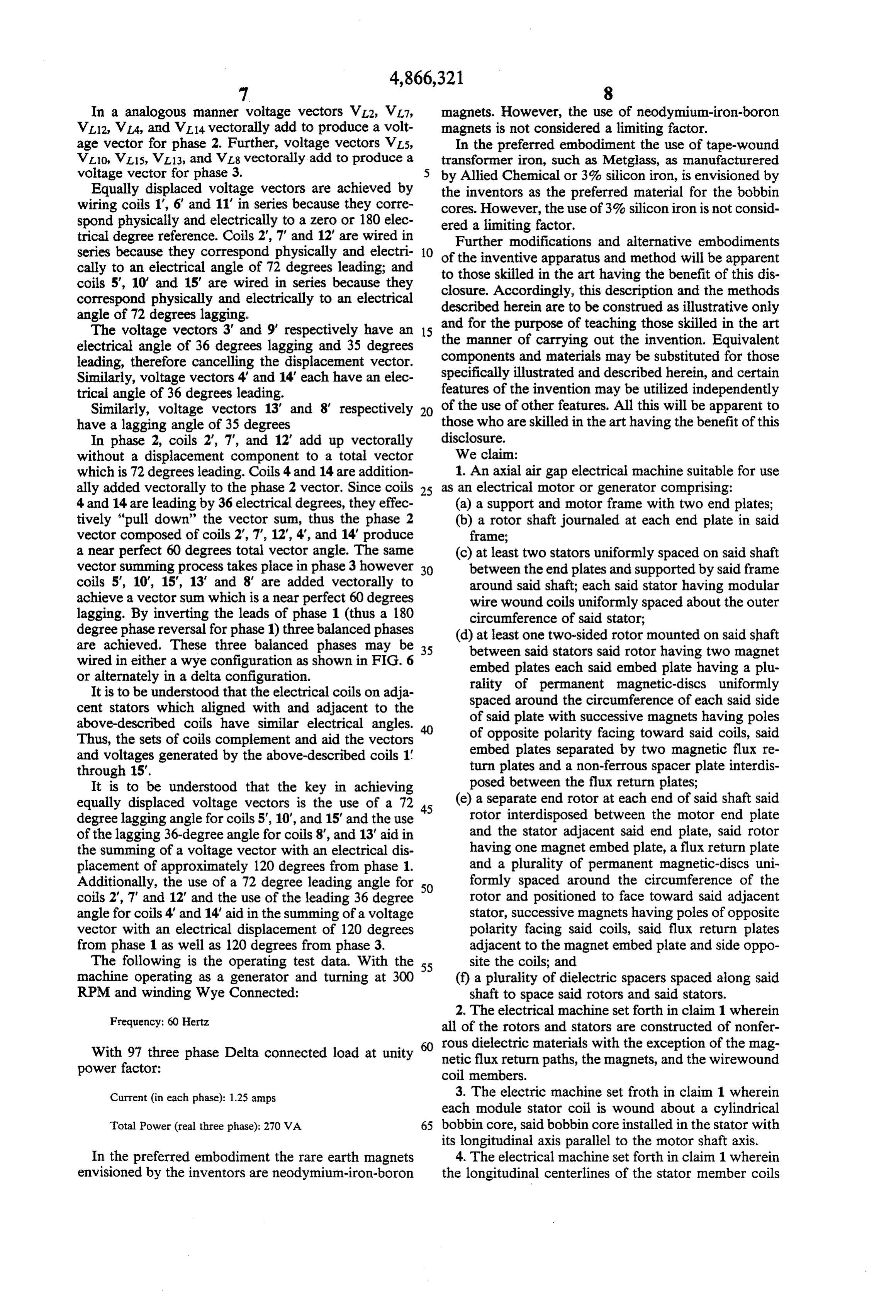
Frequency: 60 Hertz all of the rotors and stators are constructed of nonfer With 97 three phase Delta connected load at unity rous dielectric materials with the exception of the mag power factor: netic flux return paths, the magnets, and the wirewound coil members.
Current (in each phase): 1.25 amps 3. The electric machine set froth in claim 1 wherein each module stator coil is wound about a cylindrical
Total Power (real three phase): 270 VA 65 bobbin core, said bobbin core installed in the stator with its longitudinal axis parallel to the motor shaft axis.
In the preferred embodiment the rare earth magnets 4. The electrical machine set forth in claim 1 wherein envisioned by the inventors are neodymium-iron-boron the longitudinal centerlines of the stator member coils
Page 10
and the longitudinal centerline of the magnets are al stator and facing toward said magnets, the ratio of ligned. said coils to said magnets being 5 to 8; and 5. The electrical machine set forth in claim 1 wherein (f) a plurality of dielectric spacers spaced along said the rare earth magnet members are cylindrical in shape 5 rotatable shaft to space said rotor and said stators. with a diameter greater than the length. 11. An electrical machine as set forth in claim 10 in 6. The electrical machine set forth in claim 1 wherein which each dielectric rotor and stator is made of a syn there are fifteen (15) coils on each stator member, uni thetic polymer.
12. An electrical machine as set forth in claim 10 in formly spaced about the circumference of the stator, which each dielectric rotor and stator is made of a poly and wherein there are twenty-four (24) rare earth mag 10 carbonate.
nets on each rotor uniformly spaced about the circum 13. An axial air-gap three phase electrical machine of ference of the rotor. modular design for use as a motor or a generator com 7. The electrical machine set forth in claim 1 wherein prising:
there are five (5) stator coils on each stator member for (a) two axially spaced end supports; each eight (8) rare earth magnets on each rotor member. 15 (b) a rotatable shaft journaled at each end in said end 8. The electrical machine set forth in claim 1 wherein Supports;
adjacent coils or a stator member are wired in parallel, (c) a plurality of dielectric disk-like stators spaced and each parallel combination is wired in series and axially along said shaft and transverse to said shaft; interconnected to form a wye or delta electrical config (d) a plurality of dielectric, disk-like rotors axially uration, in a manner to achieve equally displaced volt 20 spaced along and mounted on said shaft, said rotors age vectors 120 degrees apart; the equally displaced being interleaved with said stators to rotate with voltage vectors produced by vectorally adding the said shaft relative to said stators; vectors in phase with each other and vectorally adding (e) at least one connecting member extending be vectors with out-of-phase (complement) components to tween said end supports to assemble and support cancel such (unwanted and) out-of-phase (voltage) 25 said stators while enabling said shaft and said rotors components and thus produce the desired voltage vec to rotate relative to said stators; tor angle. (f) a plurality of removable and retrievable bobbin 9. The machine set forth in claim 8 where the primary type wound conductor coils mounted in each said components of phase 1 are in phase and at zero degrees 30 stator in spaced relation around said stator; (g) a plurality of permanent magnets mounted on electrical angle, the primary components of phase 2 each said rotor in accurately an equally spaced voltage vector are 72 electrical degrees leading, and the relation around said rotor to sweep past the coils of primary voltage vectors of phase 3 are 72 electrical an adjacent stator upon rotation of said shaft, adja degrees lagging; and wherein the secondary voltage - cent said magnets on each said rotor arranged to vectors added to cancel unwanted components are 36 35 face poles of opposite polarities toward the coils of electrical degrees lagging and 36 electrical degrees the adjacent stator;
leading. (h) each coil of each stator being in axial alignment 10. A modular type three phase electrical machine with a coil of each other stator and each magnet of suitable for use as a motor or generator comprising: each rotor being in axial alignment with a magnet (a) a rotatable shaft; of each other rotor, the number of coils on each (b) at least one circular disk-like dielectric rotor stator to the number of magnets on each rotor mounted on said shaft; being in the ratio of 5 to 8; (c) at least two separate circular disk-like dielectric (i) a magnetic flux conductor member attached to the stators mounted around said shaft adjacent and 45 side of each said rotor away from its adjacent said axially spaced from and on each side of said rotor, stator to provide a flux return path for the magnets said stators also connected to each other by at least on said rotor; and one rod; (j) dielectric spacer members along said shaft to main (d) a plurality of permanent magnets mounted around tain axial spacings between said stators and said Otors.
the periphery of each side of said rotor uniformly 50 14. The electrical machine of claim 13 in which the spaced around the circumference of the rotor and rotor between each pair of adjacent stators is a double facing toward said adjacent stator, successive mag sided nets in said periphery having poles of opposite spacer rotor comprising two rotors and a dielectric between said rotors.
polarities facing toward said coils to sweep past the 15. The electrical machines of claim 13 in which the coils of the stator, each said side of said stator also 55 dielectric components are made of a polycarbonate. having a magnetic flux return path for the perma 16. An electrical machine as set forth in claim 13 in ment magnet associated with the side; which each said rotor has 24 magnets and each said (e) a plurality of removable and retrievable bobbin stator has 15 coils.
type coils mounted around the periphery of said k : s k t
Page 11
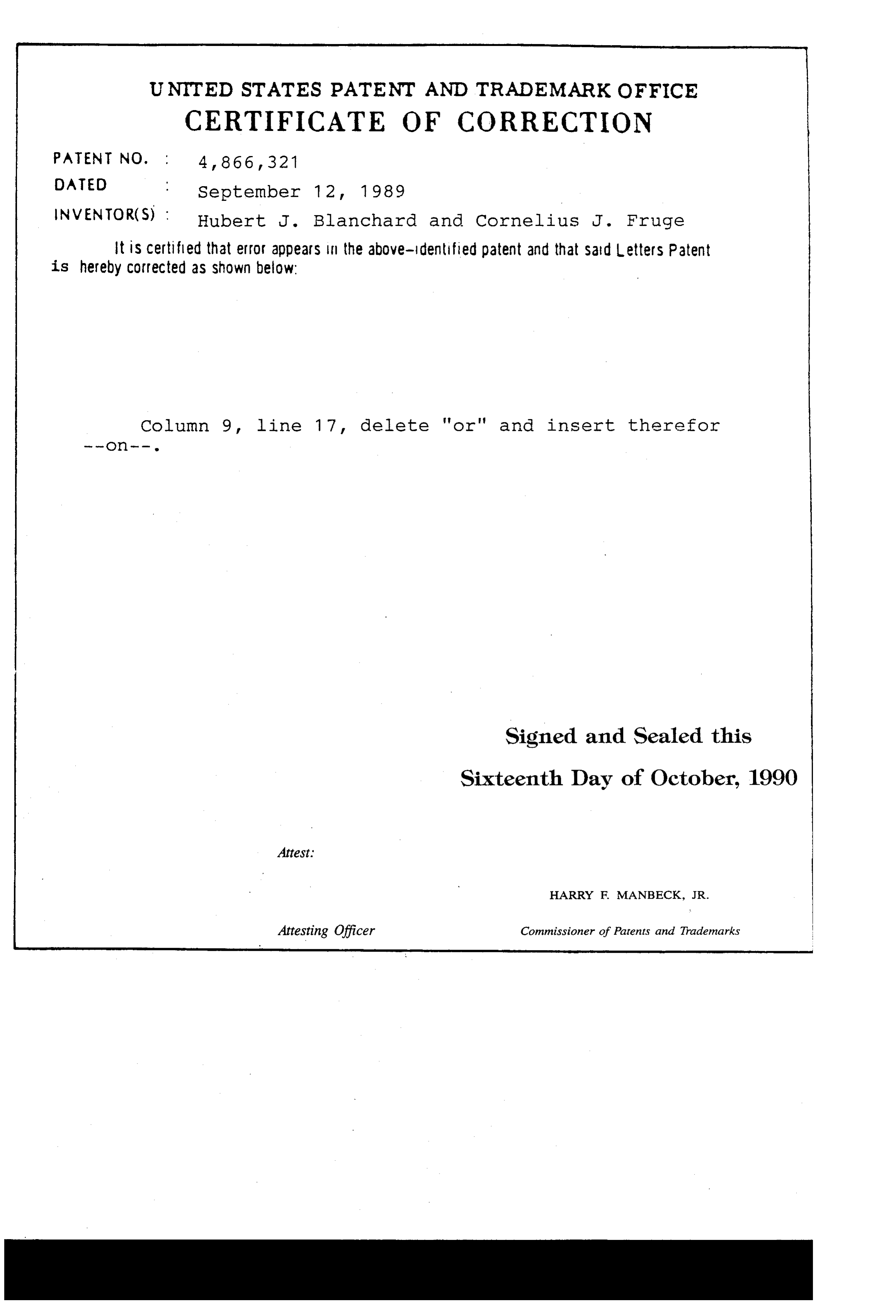
UNITED STATES PATENT AND TRADEMARK OFFICE
CERTIFICATE OF CORRECTION
NVENTOR(S) : Hubert J. Blanchard and Cornelius J. Fruge It is certified that error appears in the above-identified patent and that said Letters Patent is hereby Corrected as shown below:
Column 9, line 17, delete 'or' and insert therefor
Signed and Sealed this
Sixteenth Day of October, 1990
HARRY F. MANBECK, JR.
Attesting Officer Commissioner of Patents and Trademarks
Provenance
- Collection
- Cited prior art
- Original PDF
- patentimages.storage.googleapis.com →
- Filed
- 1985-03-26
- Pages
- 11
- Method
- pdftotext (the PDF's own text layer) + pdftoppm 300dpi page scans
- Source
- Google Patents bibliographic record
- Granted
- 1989-09-12
- Inventors
- Hubert J. Blanchard; Cornelius J. Fruge; LAMB WILLIAM C A CORP OF LA; SYNCHRO-MAGNETIC ENERGY Ltd LOUISIANA A LOUISIANA CORP
- Transcribed from
- patentimages.storage.googleapis.com →