patent · US3789252
Two-part stator for large rotating electrical machines
29 January 1974
Page 1 — bibliographic record
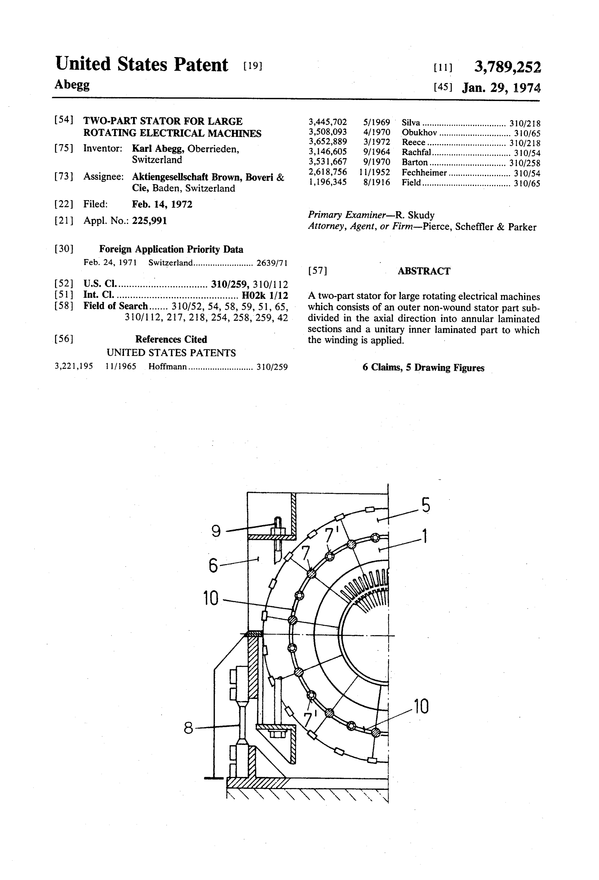
United States Patent (19) [11] 3,789,252 Abegg (45) Jan. 29, 1974 (54) TWO-PART STATOR FOR LARGE 3,445,702 5/1969 Silva................................... 310/218 ROTATING ELECTRICAL MACHINES 3,508,093 4/1970 Obukhov.............................. 310/65 3,652,889 3/1972 Reece................................. 310/218 75) Inventor: Karl Abegg, Oberrieden, 3,146,605 9/1964 Rachfall................................. 310/54 Switzerland 3,531,667 9/1970 Barton................................ 310/258 73) Assignee: Aktiengesellschaft Brown, Boveri & 2,618,756 1/1952 Fechheimer.......................... 310/54 1,196,345 8/1916 Field..................................... 310/65
Cie, Baden, Switzerland
(21) Appl. No.: 225,991 Primary Examiner-R. Skudy
Attorney, Agent, or Firm-Pierce, Scheffler & Parker 30 Foreign Application Priority Data
511 Int. Cl. ............................................. H02k 1/12 A two-part stator for large rotating electrical machines 58 Field of Search....... 310/52, 54,58, 59, 51, 65, which consists of an outer non-wound stator part sub 310/112, 217, 218, 254, 258, 259, 42 divided in the axial direction into annular laminated sections and a unitary inner laminated part to which 56) References Cited the winding is applied.
UNITED STATES PATENTS
3,221,195 1 1/1965 Hoffmann........................... 310/259 6 Claims, 5 Drawing Figures
NRN
ZZZYZZYZZY
Page 2
Drawing sheet — no readable text.
Page 3
Drawing sheet — no readable text.
Page 4
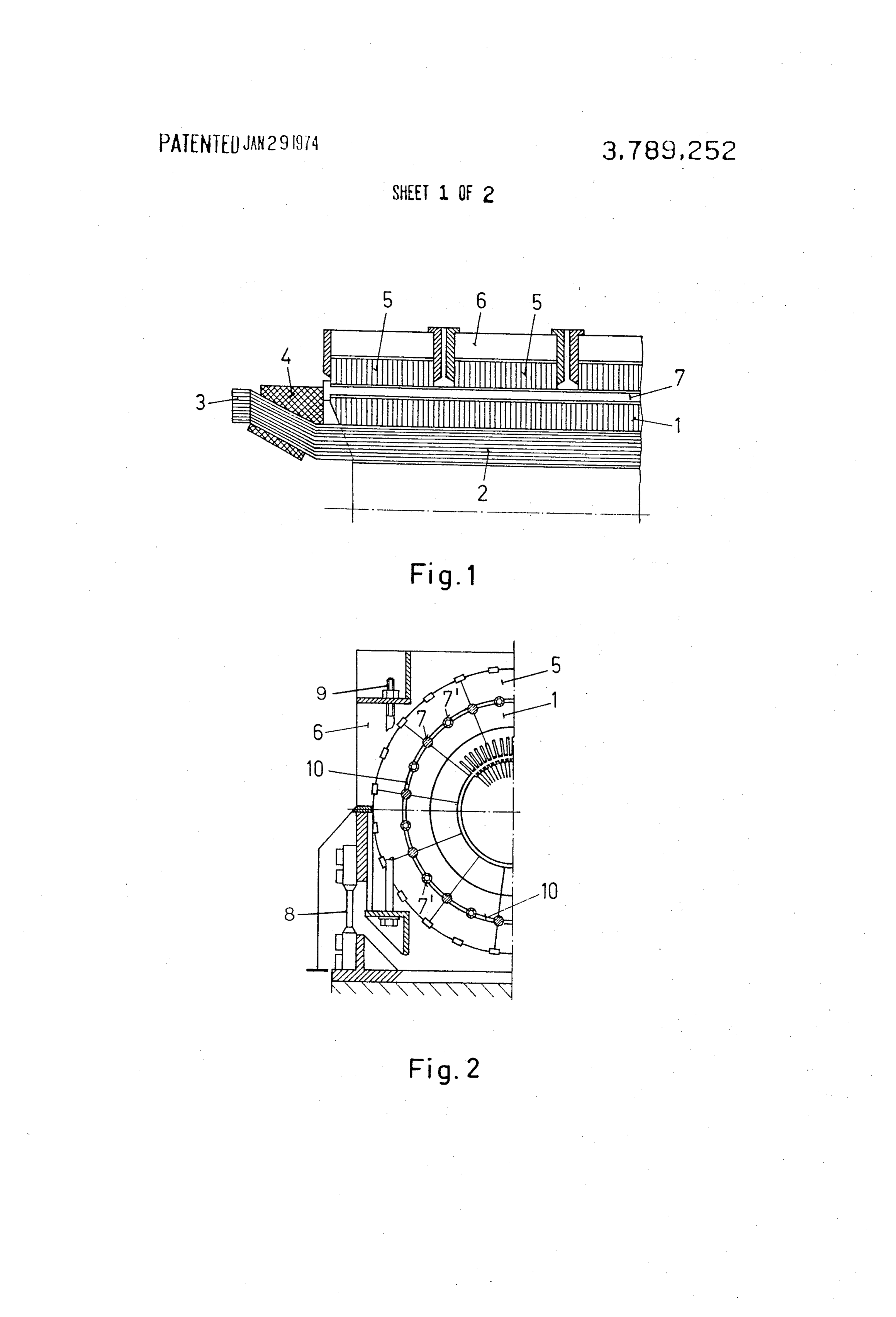
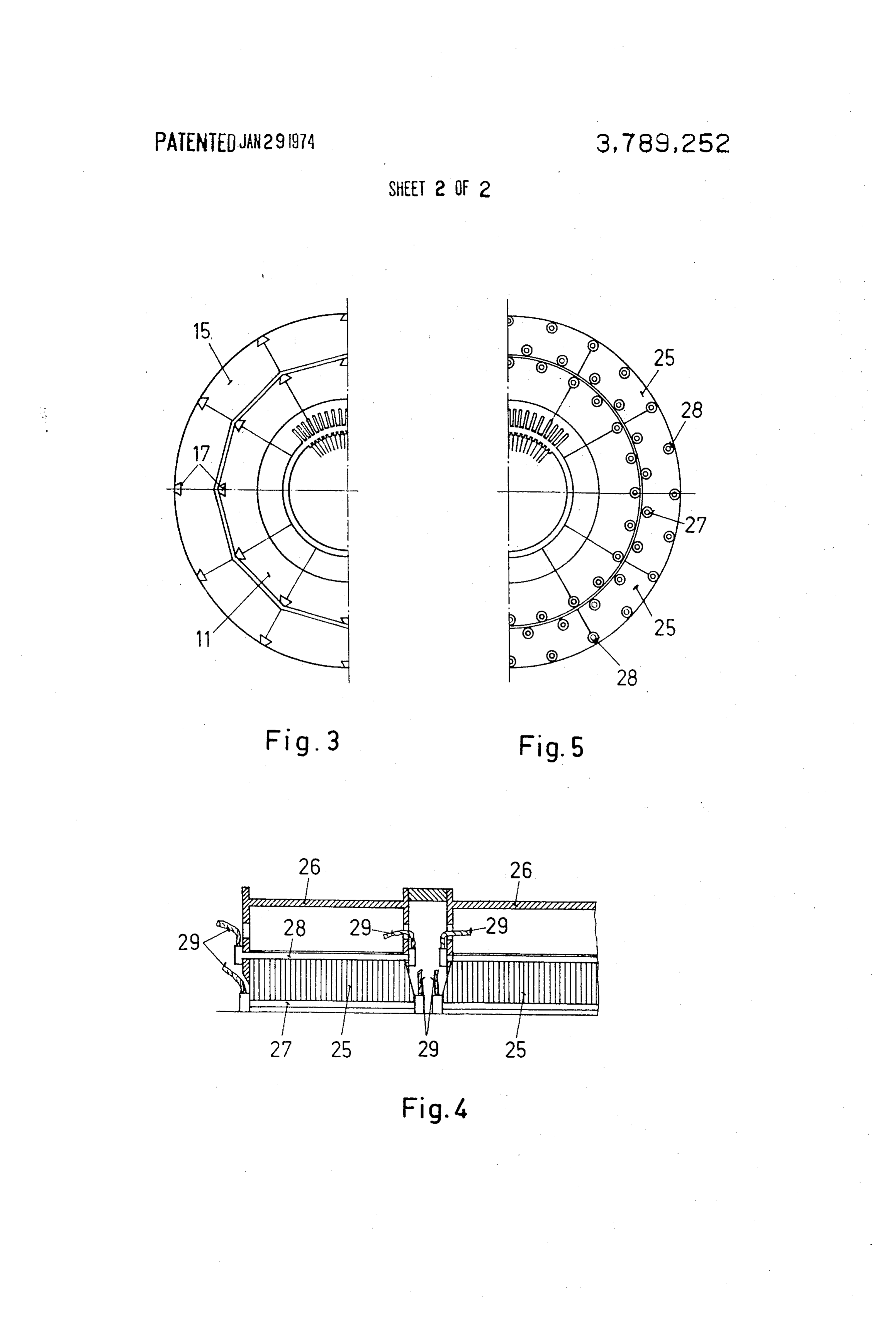
TWO-PART STATOR FOR LARGE ROTATING FIG. 4 alongitudinal sectional view of part of a stator ELECTRICAL MACHINES in accordance with a further embodiment of the inven tion,
The invention concerns the construction of a two FIG. 5 across-sectional view of the stator according part stator for large rotating electrical machines. to FIG. 4.
The exponentially increasing power demand necessi In the embodiment of the invention shown in FIGS. tates the provision of 2 and 4 pole generators, the out 1 and 2, the inner stator consists of a single laminated put of which is increased by a better utilisation of the unitary body 1 provided with teeth for carrying 3 of material and more efficient cooling systems. This is ac which are held by supports 4. The outer stator which companied by a constant increase in the dimensions of 10 surrounds the inner stator and is spaced therefrom is the machines and their transportation weight. divided in the axial direction into a number of annular Although large power stations are generally located laminated parts 5 which are arranged in a correspond at the coast or near navigable rivers, weight restrictions ingly subdivided stator casing 6. These annular parts 5 frequently cause difficulties in connection with the can furthermore be divided in the circumferential di transportation of the heavy machine parts, particularly 15 rection into segments. The laminated parts 5 of the the generator stators. In such cases it is possible to as outer stator and the laminated body 1 of the inner sta semble the stator in the power station, this being the tor are held together by means of press bolts 7 which usual procedure with large hydraulic power stations. are so arranged that they are in engagement with the Such a solution, however, prevents the manufacturer laminated elements of both stator parts and thus also from undertaking any acceptance tests in the factory, 20 prevent a relative rotation between the inner and outer unless additional risks due to intermediate erections stator. Forces acting on the inner stator can be trans are taken into account, whilst in the case of large ther mitted to the foundation either directly or by way of mo-nuclear power stations where the erection pro spring elements 8 located on the casing 6 of the outer grammes are already very complicated additional diffi 25 stator. The upper part of the stator casing 6 is con culties are encountered. nected to the lower part of the casing by means of ten In connection with smaller electrical machines, it is sion bolts 9. The intermediate space between the inner known to manufacture the stator core in the form of and outer stator can be filled at least partly with insulat two cylindrical laminated bodies of which one can be ing material.
inserted into the other, whereby one body carries the 30 A cooling medium can also flow through the interme stator winding and both bodies are joined together by diate space between the inner and outer stator whereby means of a metallic adhesive material. an improved cooling of the stator laminations is This kind of stator construction is, however, not suit achieved. It is also possible to construct at least some able for high power generators with a small number of of the press bolts 7 in the form of cooling tubes which poles, a stator length of about 10 metres and a stator 35 are made of non-magnetic material and through which diameter exceeding 2 metres, because the outer stator a liquid coolant, for instance water, flows. These cool body then becomes so large that it cannot be trans ing tubes, indicated in FIG. 2 by 7', are insulated from the inner and outer stator.
ported.
The object of the invention is to provide a two-part FIG. 3 shows a cross-sectional view of a stator where stator for large rotating electrical machines which con 40 inner periphery the of the outer stator 15 and the outer sists of an outer laminated body (outer stator) and an periphery of inner stator 11 have polygonal contours. inner laminated body (inner stator) which carries the In this way it is possible to obtain a very simple connec winding, whereby the transportation weights are kept tion between the two stator parts 15 and 11 where a rel ative rotation of these parts is impossible. The press within admissible limits and at the same time it is possi bolts ble to perform acceptance tests in the manufacturer's by numeral 45 for the stator laminations are indicated in the FIG.
workshops without taking any risks or causing addi 17.
A further embodiment tional costs in the power station. In accordance with ing to the invention is shown of the two-part stator accord in longitudinal and cross the invention this is achieved in that the outer stator is section in FIGS. 4 and 5 respectively. subdivided in the axial direction into several annular The outer stator laminated parts and the inner stator is in one piece. 25 is again subdivided in the axial direction into several laminated parts 25 which are provided
A further advantage in connection with the construc axial press bolts 27, 28 having any desirable contour. with hollow tion according to the invention is that the lifting capac ity of the cranes in the power station can be chosen for Theseand press bolts are connected by means of supply discharge pipes 29 to a liquid cooling system and the usual transportation weights and do not have to the cooling liquid flows through the stator casing 26.
take into account the maximum weight of the generator The ends of adjacent stator. Also complicated and expensive hoisting equip laminated parts 25 are provided ment such as is required for the stator erection in with press plates which consist of magnetic laminations power stations having a limited crane capacity can be which are glued together and bevelled in such a manner avoided. that the width of the press plates decreases from the in Several constructional forms of the invention are 60 side to the outside of the outer stator 25. In this way it now explained by means of the accompanying drawings the is possible to obtain a good magnetic coupling between where inner and outer stator and the pipes for the cooling liquid
FIG. 1 shows part of a stator in longitudinal section, that therecan be located between the laminated parts, so is only a minimum reduction in the width of
FIG. 2 a cross-sectional view of the stator according 65 the iron. The to FIG. 1, necessary connection between the outer FIG. 3 a cross-sectional view of a stator in accor and inner stator which must not allow any relative rota tion between these parts, can for example be achieved dance with another embodiment of the invention, by gluing the parts together by means of a thin layer of
Page 5
insulation combined with a synthetic resin, or by means with teeth for carrying a stator winding, said outer sta of an arrangement analogous to that illustrated in FIG. tor member being subdivided in the axial direction into 3. annular laminated parts and the inner stator member The two-part stator construction according to the in being undivided in the axial direction, and bolt means vention has a number of important advantages. Both for connecting together the inner and outer stators in stator parts are so firmly connected together that vibra spaced relation and to compress the laminated body of tions of the laminations during normal operation can the inner stator, thereby enabling the outer stator to be not attain dangerous amplitudes and the torque which occurs during normal operation or the case of a short assembled on the inner stator at the installation site. 2. A two-part stator as claimed in claim 1 wherein circuit can be absorbed. By means of the use of grain 10 said bolt means comprise press bolts. oriented laminations in the inner and outer stator, it is 3. Two-part stator as in claim 2, characterised in that possible to obtain optimal results as regards the size the press bolts consist of tubes through which a cooling and weight of the stator, so that the inner part of the medium is caused to flow.
stator together with its winding can be tested, trans ported, and installed as a single unit. After the inner 5 4. Two-part stator as in claim 1, characterised that a stator has been tested in the manufacturer's factory, it cooling medium flows through the axial intermediate can be transported without any difficulty, just like the space between the inner and outer stator. rotor of machine, by means of the usual available trans 5. Two-part stator as in claim 1, characterised in that port equipment. Furthermore it is possible to cool the the axial intermediate space between the inner and stator in a very efficient manner. 20 outer stator is at least partly filled with an insulating claim: material.
1. A two-part stator for large diameter rotating elec 6. Two-part stator as in claim 5, characterised in that trical machines consisting of an outer laminated non the inner stator is joined to the outer stator by means toothed stator member, an inner laminated stator mem of a synthetic resin.
ber spaced from said outer stator member and provided 25 sk ck k ck k
Provenance
- Collection
- Cited prior art
- Original PDF
- patentimages.storage.googleapis.com →
- Filed
- 1972-02-14
- Pages
- 5
- Method
- pdftotext (the PDF's own text layer) + pdftoppm 300dpi page scans
- Source
- Google Patents bibliographic record
- Granted
- 1974-01-29
- Inventors
- K Abegg; Bbc Brown Boveri & Cie
- Transcribed from
- patentimages.storage.googleapis.com →