patent · US5609184
Regulating device
11 March 1997
Page 1 — bibliographic record
United States Patent (19) 11 Patent Number: 5,609,184.
Apel et al. 45) Date of Patent: Mar 11,9 1997
54 REGULATING DEVICE 4,694,390 9/1987 Lee.......................................... 137/554 4,967,792 11/1990 Magee ..................................... 137/554 (75) Inventors: Peter Apel, Suedkirchen; Marion 5,148,106 9/1992 Ozawa .......... ... 324/207:21 Hauschopp; Klaus Wilczek, both of 5,257,014 10/1993 Zimmermann .......................... 137/554 Werne, all of Germany FOREIGN PATENT DOCUMENTS 73) Assignee: AB Elektronik GmbH, Werne, 4021691 1/1992 Germany. Germany 2275030 9/1990 Japan.
(21) Appl. No.: 491951 Primary Examiner A. Michael Chambers 22, PCT Filed: Nov. 18, 1994 Attorney, Agent, or Firm-Furgang & Milde, LLP 86 PCT No.: PCT/EP94/03825 (57) ABSTRACT S371 Date: Sep. 20, 1995 The proposed device is intended for use in motor vehicles 9 and permits a high level of accuracy in measurement and S 102(e) Date: Sep. 20, 1995 simple and cost-effective manufacture. It comprises a shaft component (12) arranged adjustably in a housing element 87). PCT Pub. No.: WO95/14911 (21) and a rotating unit (20') of a rotation angle sensor (2) PCT Pub. Date:Jun. 1, 1995 which can move in relation to the fixed unit (20). The stator element (21) consists of two rounded cusp-shaped subcom 30 Foreign Application Priority Data ponents held with a bracing unit and secured in a stator Nov. 20, 1993 (DE) Germany ............................ 93.17797 U mount (23). There is a clearance recess between the sub components of the stator element. The rotating unit (20') is 51) Int. Cl. ... F16K 31/02 a ring-shaped magnet element (24) held by a magnet holder 52 U.S. Cl. ............... 137/554; 251/129.04; 251/129.11; (26,27) connected to the shaft element (12); this arrange 251/368 ment allows the magnet element (24) to move around the (58) Field of Search ..................................... 137/554, 553; stator element subcomponents leaving an air gap (25). The 251/368, 129.04, 129.11 housing element (13) can be constructed in many parts. The stator mount (23) and parts of the multiple-component (56) References Cited housing element (13) can be moulded from an electrically conducting long-fibre granulate with 1%-10% by volume
3,602.254 8/1971 Fawkes .................. 137/554 shielding against electromagnetic influences. 4,316,254 2/1982 Levin et al. ... 324/72.5 4,601,211 7/1986 Whistler .................................. 137/554 17 Claims, 6 Drawing Sheets
SNSYNYS
2 NSM
Page 2
Drawing sheet — no readable text.
Page 3
Drawing sheet — no readable text.
Page 4
Drawing sheet — no readable text.
Page 5
Drawing sheet — no readable text.
Page 6
Drawing sheet — no readable text.
Page 7
Drawing sheet — no readable text.
Page 8
REGULATING DEVICE The stator-tensioning subassembly ensures that the stator will be positioned precisely in its holder and will not need
BACKGROUND OF THE INVENTION
to be adjusted to the rotating components. Again, the stator tensioning subassembly represents a simple means of pre
The present invention relates to a regulating device. venting rotation and displacement on the part of the stator components, which will remain stationary enough to provide
A magnetic probe is known from the published Interna precise and reproducible results.
tional Patent Application No. WO92/10722. It comprises a It is of advantage for the stator components to have at last magnet that surrounds a rotating shaft and a stator associated one approximately 45 bezel and at least one accommodat with the magnet. The stator is secured to a housing by a 10 ing bore for a tensioning pin to extend through. The bezels holder. A Hall sensor and an exciter coil face each other in a recess in the stator. affect the magnetic flux and increase the precision of the angle-of-rotation sensor. The stator components can com
Although this probe has been proven, it needed to be prise stamped-out blanks of specially treated, "textured', further developed for use in motor vehicles. sheet metal stacked into packages. The stator components An overall throttle-valve assembly is known from the 15 are designed in particular to prevent magnetization losses in German Patent No. 4,021,691 A1. It comprises a housing the stator from contaminating the results.
accommodating a throttle valve that spins on a shaft. It is also of advantage for the stator-tensioning subassem Attached to the shaft are a potentiometer and a transmission. bly to comprise an essentially round stator-tensioning plate The transmission is powered by an electric motor. A regu and at least one stator-tensioning pin for each stator. The lating device compares signals representing engine speed, plate rests on the stator and is secured to the base of the for example, and intercepted by the potentiometer and stator holder by the pins extending through the stator com regulates the throttle valve by way of the motor. ponents. The resulting tension maintains the blanks of sheet There is a drawback in that, since the mechanisms and metal in each stator precisely stacked and secured to the base regulating device are accommodated in a housing, the whole of the stator holder. The stator-tensioning pins have two valve must be removed and replaced in the event of a 25 functions. First, they prevent lateral displacement on the part malfunction. It is too expensive to repair the defective of the individual blanks. Second, they maintain the tightness components, so that the whole useless valve must be dis of the overall stack and prevent the blanks from rotating. carded. Another drawback is that the potentiometer is not This objective is attained in particular in that the stator precise enough. tensioning plate and the stator-tensioning pins and their 30 attachment to the base of the stator holder are of thermo
SUMMARY OF THE INVENTION plastic. It is preferable for the plastic to be injection-molded. This approach exploits the plastic's properties of ductility,
The object of the present invention is accordingly to so elasticity, and permanence. Such particular stresses as improve a regulating device that operates magnetically in 35 impact, heat, moisture, etc. will have no affect on the conjunction with a angle-of-rotation sensor that (1) they can stator-tensioning subassembly's tensioning and securing be used in motor vehicles, (2) they are very precise, and (3) capacities.
they can be manufactured easily and cost-effectively. It is also of advantage for the clearance between the stator This object as well as other objects which will become components to accommodate an electromagnetic compo apparent from the discussion that follows, are achieved in 40 nent, a Hall sensor for example. This approach ensures accordance with the present invention, by providing a shaft extremely precise results. The results will also be especially component arranged adjustably in a housing element and a precise when the stator comprises two components shaped rotating unit of a rotation angle sensor which can move in like segments of an orange and with clearance between relation to the fixed unit. The stator element preferably them. Such components will render the magnetic flux linear. consists of two rounded cusp-shaped subcomponents held 45 It is preferable to pack the clearance with resin to prevent the with a bracing unit and secured in a stator mount. A Hall sensor from oscillating. It is of course also possible to clearance recess is provided between the subcomponents of pack the clearance with any other material that has similar the stator element. The rotating unit is a ring-shaped magnet or identical properties.
element held by a magnet holder connected to the shaft The magnet-holder subassembly preferably comprises a element; this arrangement allows the magnet element to 50 hollow cylindrical magnet holder and a spacing disk. The move around the stator element subcomponents leaving an spacing disk is attached to the shaft and can be introduced air gap. into and secured in the magnet holder. The magnet holder, The particular advantages obtainable in accordance with the spacing disk, and the magnet accordingly constitute a the present invention are that the magnet can be secured rotor, itself attached to the shaft. The rotor is protected by directly to the shaft by the magnet holder and the stator and 55 and can move freely inside the stator holder. electromagnetic components directly to the housing that It is also of advantage for the annular magnet to be a houses the overall throttle-valve assembly or a similar hollow cylinder that can be introduced into and secured in structure by the stator holder. It is accordingly possible to the magnet holder. This system makes it possible for the manufacture these subassemblies independent of the overall rotating components of the angle-of-rotation sensor to fit assembly. The result is the major advantage that the com together and be easily installed. The magnet can be a ponents comprising the angle-of-rotation sensor can be permanent magnet. It can be made of the materials ordinarily attached to overall throttle-valve assemblies of different employed for permanent magnets. It is of course also types. Maintenance and repair etc. are also essentially more possible to employ an electromagnet instead of a permanent cost-effective and rapid. magnet.
Another very essential advantage is that the stator-ten 65 It is also of advantage for the housing to constitute an sioning subassembly secures the stator in the stator holder overall throttle-valve assembly in at least two separate without screws or other fasteners. sections, specifically a throttle-valve housing section, an
Page 9
actuator housing section, a regulating-mechanism housing possible to stack all three subassemblies together. The section, and a electronics housing section. In this event a tripartite division of the housing will in this event provide throttle valve and its shaft are accommodated in the throttle the particular advantage of a wide range of variation and valve housing section with the shaft extending out of it. The adaptation to various applications and needs. components of the angle-of-rotation sensor, specifically the It is also of advantage for either the throttle-valve housing stator, which is accommodated in the stator holder, and the section and the actuator housing section or the throttle-valve annular magnet, which is secured by the magnet holder and housing section and the regulating-mechanism housing sec by the spacing disk, are accommodated along with a trans tion and optionally the electronics housing section to be mission subassembly, a circuitry subassembly, and a motor attached together by prongs or clips or both. "Prongs” are to subassembly in at least one other section of the housing, 10 be construed in this context as protective-contact prongs, specifically the actuator housing section, the regulating electronics prongs, etc. "Clips' are essentially specially mechanism housing section, or the electronics housing sec shaped springs that snap into a projection or recess etc. The tion. Once the actuator housing and the regulating-mecha prongs and clips allow the three housing sections to fit nism housing are in position on the throttle housing together smooth and tight and be easily separated. The result accommodating at least the angle-of-rotation sensor and the transmission subassembly, the shaft that extends out engages 5 is particularly simple assembly and disassembly. both the transmission subassembly and the spacing disk in The throttle-valve housing section can be a casting, espe the angle-of-rotation sensor, creating a force fit connection. cially a light-metal casting.
A "regulating device' is to be construed hereinafter as not It is also of advantage for the stator holder to be a hollow only an overall throttle-valve assembly with a angle-of 20 cylinder open along one side and secured at its wall to the rotation sensor but also as an overall throttle-lever assembly open side of the throttle-valve housing section or to the with a rotating or similar mechanism that rotates a shaft to transmission-subassembly housing section. The stator an extent monitored by an integrated angle-of-rotation sen holder accordingly not only assumes the function of holding SO. the stator but also acts as an exterior protection for the The separate accommodations for the essential subassem 25 housingoverall angle-of-rotation sensor. The direct connection to the blies involved in an overall throttle-valve assembly in sepa makes it possible to encapsulate the overall angle rate housing sections makes it possible to operate them of-rotation sensor tight, so that dirt, oil, dust, etc. cannot separately. Furthermore, all overall throttle-valve assemblies affect the function of the angle-of-rotation sensor. can be provided with subassemblies of only a few basic The circuitry subassembly can be accommodated in a designs. What is essential is that it accordingly becomes 30 central depression in the housing. The electric component is possible to provide new or rebuilt overall throttle-valve accordingly protected from both mechanical stress and from assemblies deriving from different manufacturers with the such environmental factors as dust and oil. The circuitry same type of regulating device. Defective regulating devices subassembly can also have a receptacle that the stator holder can be replaced with new ones in the course of repair with can be inserted into.
little intervention and with no need to remove the overall 35 The stator holder in another embodiment of the present throttle-valve assembly and scrap it if necessary. The prong invention is a cap that can be manufactured along with the in type of force fit represented by the throttle-valve shaft central depression, the actuator housing section, the regu between the angle-of-rotation sensor and the transmission lating-mechanism housing section, and the electronics hous subassembly can be rapidly disestablished and re-estab ing section of a plastic material, plastic itself for example 40 and especially a high-strength plastic or an electrically lished.
It is also of advantage for the angle-of-rotation sensor, the conductive thermoplastic or both. The particular material transmission subassembly, the circuitry subassembly, and depends on the particular application. the motor subassembly to be combined into a throttle-valve It is also of advantage for the actuator housing section, the regulating mechanism. Such a mechanism can be accom regulating-mechanism housing section, and the electronics modated in an actuator housing section constituting the 45 housing section to be molded ready to use with its electrical second section of the housing. The electric and mechanical and mechanical accommodations already in and through it controls are all accommodated in the same housing section from an electrically conductive thermoplastic reinforced in this embodiment. Fitting the throttle-valve housing sec with steel fiber. The result is housing sections that are simple tion and actuator housing section together automatically and can in particular be molded ready to use while exhibiting establishes the aforesaid form fit represented by the throttle 50 the properties of an essentially more complicated to manu valve shaft between the angle-of-rotation sensor and the facture metal housing section. The electrically conductive transmission subassembly on the one hand and an automati thermoplastic makes it possible to produce almost any shape cally aligning connection at the other end. The transmission with high accuracy. Convexities, concavities, and perfora Subassembly can be accommodated in a transmission hous tions can be handled without molding problems. ing section. 55 It is also of advantage for the electrically conductive It is also of advantage for the angle-of-rotation sensor, the thermoplastic to be an electrically conductive long-fiber transmission subassembly, and the motor subassembly to be granulate containing 1% to 10% steel fiber by weight. The accommodated in a regulating-mechanism housing section result will be an impedance of 10 to 100 G.2-cm, allowing constituting the second section of the housing and the shielding of 55 to 70 dB. A granulate with up to 60% by electronics subassembly to be accommodated in an elec 60 weight of fibers as long as the trimmed billet, 10 mm for tronics housing section constituting the third section of the example. Traditional short-fiber compounds have fibers only housing. The throttle-valve regulating mechanism is accord 0.3 mm long by comparison. The extremely long fibers in ingly divided into its strictly control and essentially regu accordance with the present invention provide the thermo lating components. Separating the circuitry subassembly and plastic with particular rigidity and toughness. A tensile accommodating it in a separate electronics housing section 65 strength of 43.47 to 79.35 N/mm and a modulus of elas allows the third section of the housing to be accommodated ticity of 1380 to 4830 N/mm can be attained. The material at very many points inside the vehicle. It is of course also attains a transverse strength of 42.78 to 122.82 N/mm with
Page 10
a modulus of inflection of 1380 to 4140 N/mm. IZOD Magnetizability is affected by crystalline-energy direc impact strength is 10.4 to 62.4 J/m. There are ten types of tional forces. Weakly magnetizable materials exhibit a low electrically conductive long-fiber granulates available. crystalline anisotropy that decreases even more as the ran The electric-wiring perforations are lined with plastic domly oriented crystals are forced into alignment by such insulation. It is also of advantage to keep the electrically foreign factors as rolling. Once the direction of the outer active components inside the insulating plastic. The overall field parallels the direction of least magnetizability, rema throttle-valve assembly will accordingly be ready to use. It nence will be almost at the threshold of saturation. The is also possible to line the instrumentation perforations with individual magnetic moments of the Weiss regions will plastic. It is of course also possible to use other types of already be aligned and will require no more rotation. Coer insulation instead of plastic. O cive-field strength and initial permeability are structure Terminal strips, prong-in components, and ground con sensitive state parameters that vary considerably just as a nections for example, can be molded into the housing result of slight variations in chemical composition or even sections. Such an approach will make it possible for the heat treatment or mechanical deformation. Mechanical prong-in components and ground connections to raise the 15 stresses in the material reduce the motility of the walls of the housing subassembly to a desired level of potential. A Weiss regions. These stresses can occur due to constant level of potential will discharges. a) compression or tension during magnetic excitation, The present invention will now be specified with refer b) plastic deformation accompanying shaping or heat ence to the accompanying drawing. treatment, or 20 c) magnetostrictive stress.
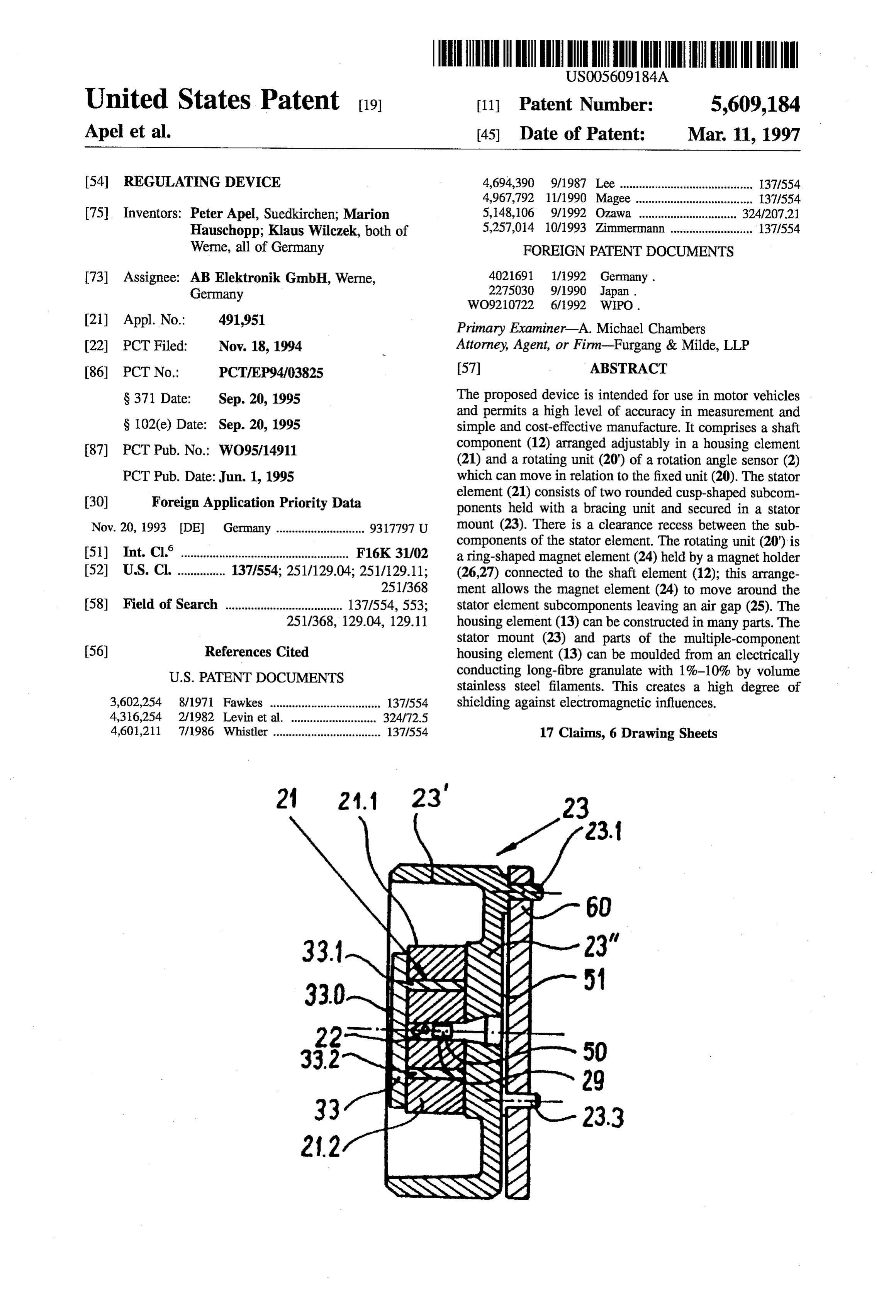
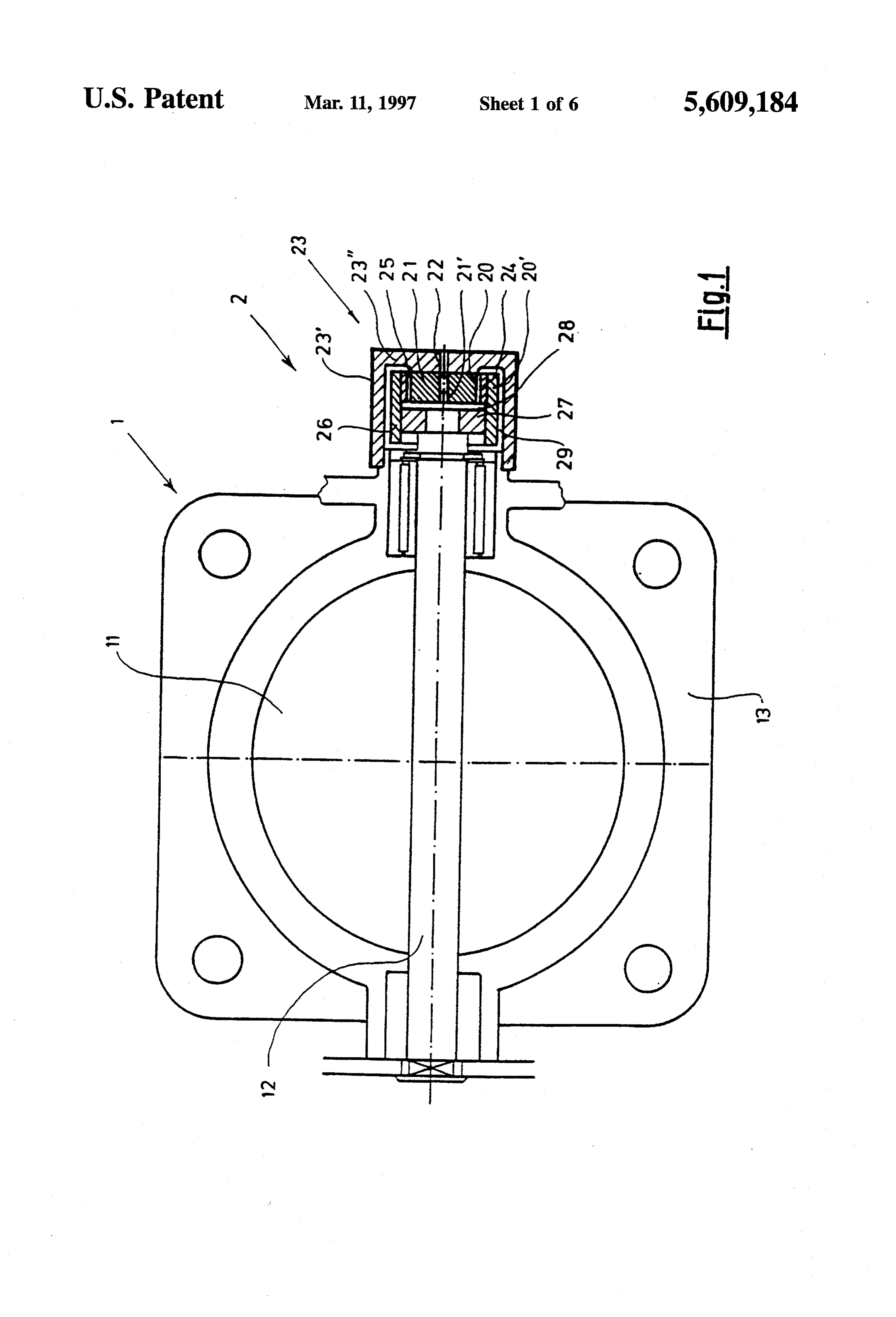
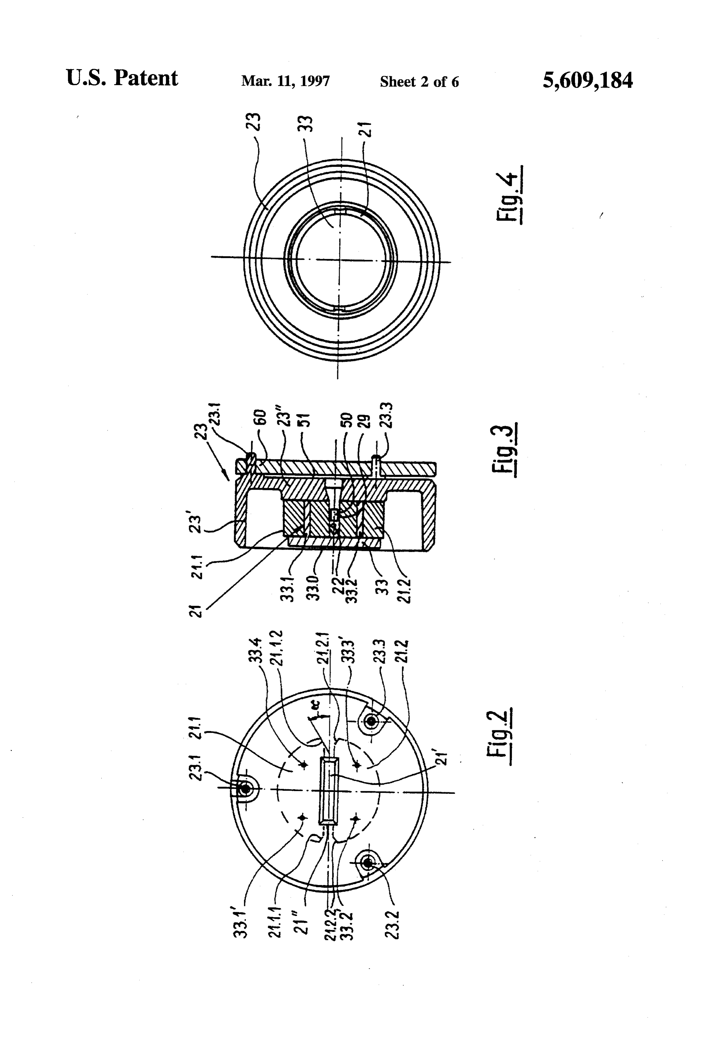
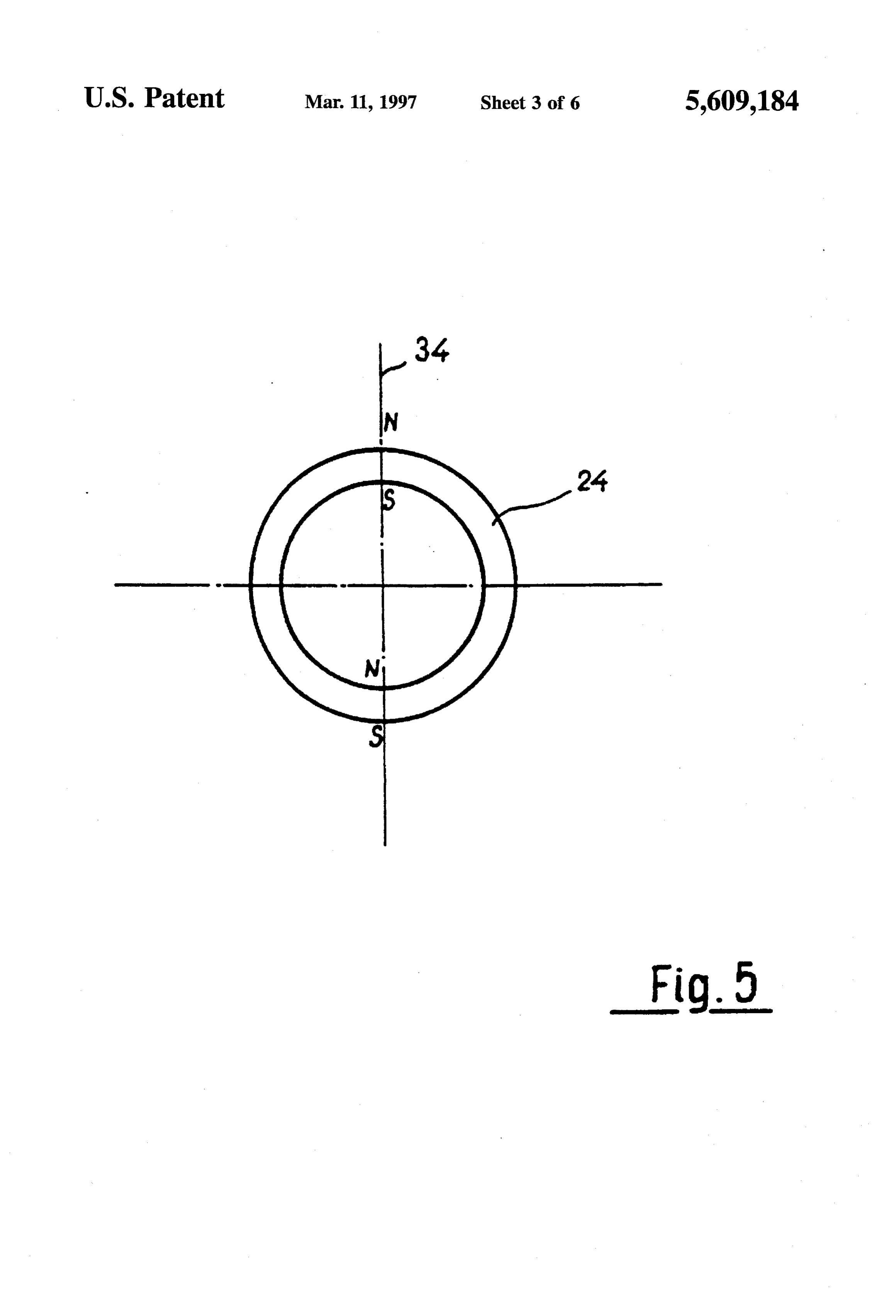
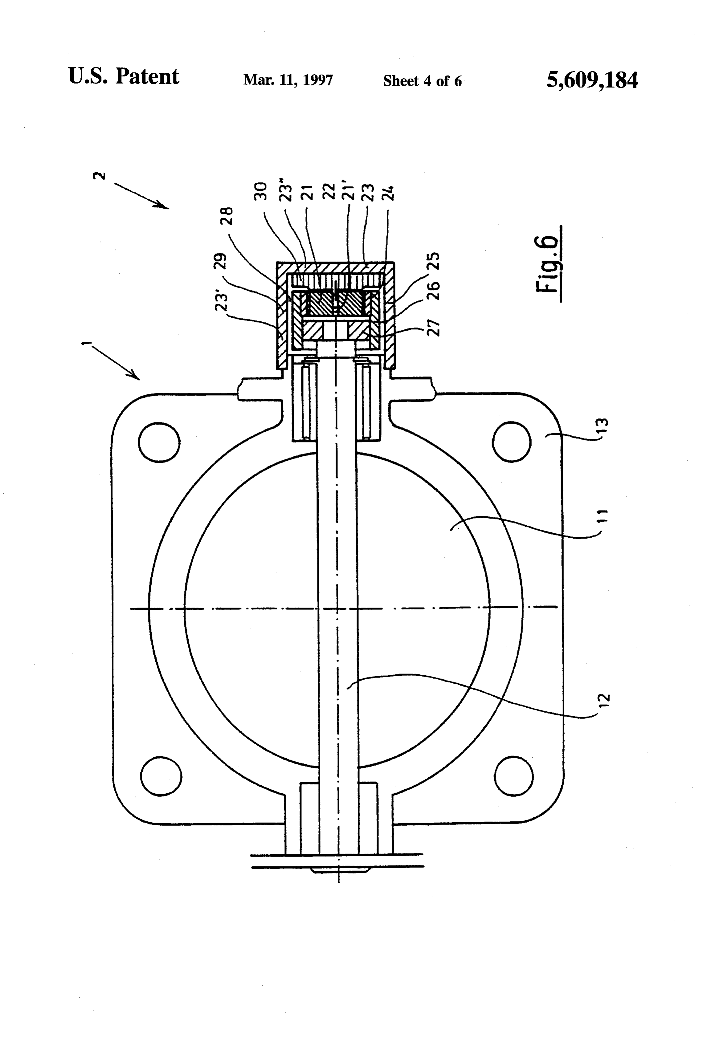
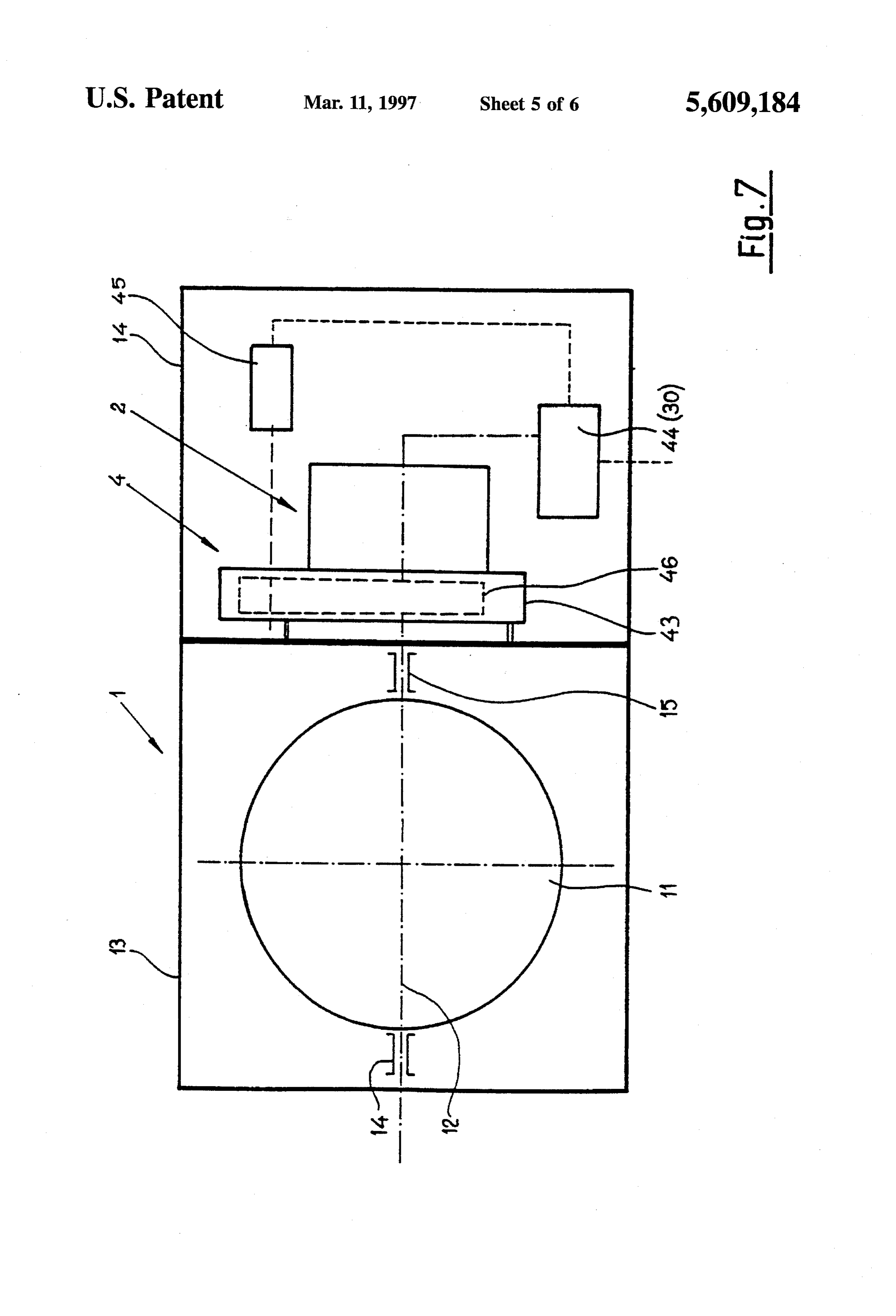
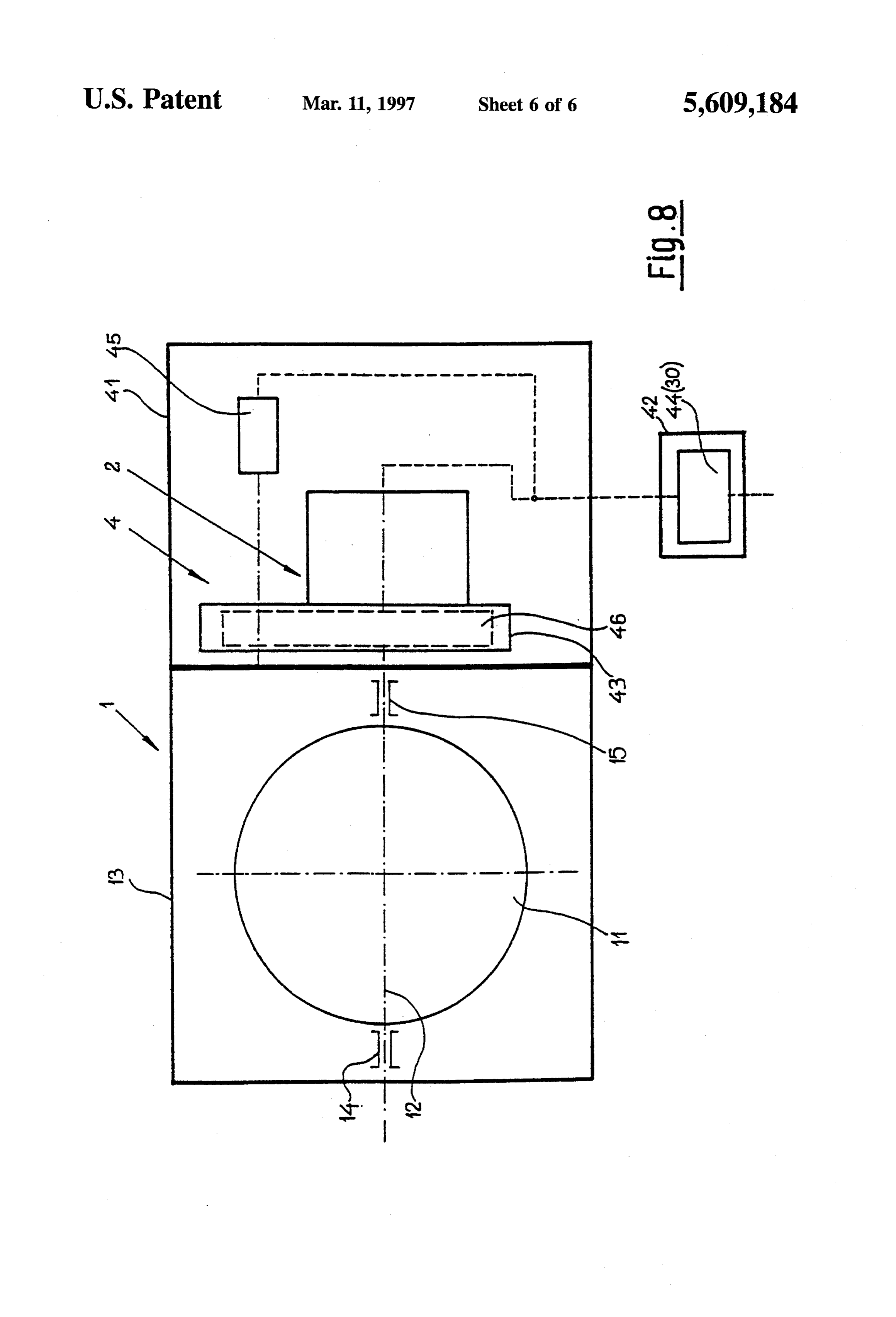
BRIEF DESCRIPTION OF THE DRAWINGS Increasing permeability basically increases sensitivity to FIG. 1 is a schematic and partly sectional view of an mechanical stress, and all mechanical shaping operations overall throttle-valve assembly with a angle-of-rotation sen that might lead to structure changes and mechanical stress sor attached, must accordingly be avoided. Because more permanent 25 deformation occurs in thicker sheets, they are more sensitive
FIG. 2 is a schematic rear view of the stationary compo than thinner sheets. The losses that derive from compressing nents of the angle-of-rotation sensor illustrated in FIG. 1, coated cores can be as high as 10% at pressures of approxi FIG. 3 is a schematic section through the stationary mately 15 kp/cm. Cold-rolled sheet has better magnetic components of the angle-of-rotation sensor illustrated in properties in the direction of rolling. They derive from FIG. 1, 30 particular crystallographic situations in the structure (tex FIG. 4 is a schematic front view of the stationary com ture). Iron and iron-silicon alloys for example are easier to ponents of the angle-of-rotation sensor illustrated in FIG. 1, magnetize along the edges of the cubes in the 100 direction FIG. 5 is a schematic front view of the rotating compo of the cubical-space lattice than along the diagonals of the nents of the angle-of-rotation sensor illustrated in FIG. 1, plane or space (cube-edge texture). An alloy of 50% nickel FIG. 6 is a schematic and partly sectional view of the 35 side and 50% iron is the easiest to excite magnetically when one overall throttle-valve assembly illustrated in FIG. 1 with a of a cube parallels the surface of the sheet and the edges circuitry subassembly accommodated in the angle-of-rota of the cube are parallel and at an angle of 90° to the larger tion sensor, field (cube-face texture). Materials with cube-face texture FIG. 7 is a schematic view of another overall throttle have outstanding rectangular hysteresis loops. Sheet metal 40 treated in this way is called textured. It is obviously also valve assembly with a two-section housing, and possible to construct stator components 21.1 and 21.2 of FIG. 8 is a schematic view of an overall throttle-valve other and otherwise processed materials. assembly like that illustrated in FIG. 7 with a housing in Stator components 21.1 and 21.2 comprising separate several sections.
blanks of thinner textured sheet are provided with tension 45 ing-pin accommodating bores 33.1, 33.2, 33.3", and 33.4 or
DESCRIPTION OF THE PREFERRED bezels 21.1.1 and 21.1.2 and 21.2.1 and 21.2.2. The stacked EMBODIMENTS components are accommodated in a stator holder in the form FIG. 1 illustrates an overall throttle-valve assembly 1 of an essentially cylindrical cap 23 comprising a wall 23' and attached to a angle-of-rotation sensor 2. a base 23". Base 23" has an elevation at the center that more 50 or less coincides with the circumference of the facing stator
Throttle-valve assembly 1 comprises a throttle valve 11 components 21.1 and 21.2. It is simultaneously possible for mounted on a shaft 12 and accommodated in a housing 13. the elevation to accommodate matching depressions coin Angle-of-rotation sensor 2 comprises a stationary sensor ciding with tensioning-pin accommodating bores 33.1, subassembly 20 and a rotating sensor subassembly 20'. 33.2, 33.3', and 33.4'. The stator components 21.1 and 21.2 Stationary sensor subassembly 20 is illustrated in detail in 55 that rest thereon are secured by a stator-tensioning subas FIGS. 2, 3, and 4. It includes a stator 21 comprising two sembly 33 comprising a plate 33.0 and pins 33.1, 33.2, and facing stator components 21.1 and 21.2 shaped like blunted 33. Plate 33.0 covers both stator components 21.1 and 21.2. crescents. The edges of stator components 21.1 and 21.2 are Pins 33.1, 33.2, and 33 extend through both the plate and the provided with bezels 21.1.1 and 21.1.2 and 21.2.1 and stator components and into accommodations in base 23". 21.2.2. Between stator components 21.1 and 21.2 is a 60 Stator components 21.1 and 21.2 are accordingly reliably clearance 21". Bezels 21.1.1 and 21.1.2 and 21.2.1 and secured and the individual blanks forced together with just 21.2.2 are at an angle O. of 45°. Stator components 21.1 and enough force to prevent increased losses and hence con 21.2 accordingly resemble segments of an orange, or, within tamination of the sensor results. It is of course also possible the bevels, of a tangerine when viewed from above. Each to injection-mold the specially compacted stator compo stator component 21.1 and 21.2 comprises a stack of blanks 65 nents 21.1 and 21.2 of plastic along with stator-tensioning stamped out of sheet metal. The metal can in particular be subassembly 33 and stator holder 23 or at least base 23" or textured. sections thereof. The base of stator holder 23 can also be
Page 11
provided with fasteners 23.1, 23.2, and 23.3 in the from of particular allows precise adjustment of subassemblies 20 dowels that can be inserted in a flat receptacle 60. Also at the and 20', facilitating manufacture and adjustability along with center of base 23" is a central depression 21 more or less in precise measurement and transmission of results. Precision the form of a groove. is further increased by the bezels 21.1.1 and 21.1.2 and As will be evident from FIGS. 2 and 3, central depression 21.2.1 and 21.2.2 on stator components 21.1 and 21.2. 21' and clearance 21" are wide enough to match to a When, specifically, magnet 24 goes out of alignment due to considerable extent. An electromagnetic component, a Hall a change in position of throttle-valve shaft 12, axis 34 will sensor 22 for example, fits into clearance 21". It is also also rotate, 45° for example. At an angle of 45 on the other possible to fill clearance 21" with resin to cushion Hall hand, the magnetic flux will travel perpendicularly through sensor 22. A circuitry subassembly 50 can be inserted in 10 bezels 21.1.1 or 21.1.2 or 21.2.1 or 21.2.2. Securing stator central depression 21'below. Since circuitry subassembly 50 21 by means of a stator-tensioning subassembly 33 will is a printed circuit, it can easily fit in central depression 21'. accordingly also ensure reliable and precise security even It is of course also possible for such a circuitry subassembly when the sensor is subjected to considerable jolting. It is 50 to be inserted first into clearance 21" and simultaneously accordingly ensured that angle-of-rotation sensor 2 will, due into the resin. It is also possible to introduce the resin into 5 to its special security system, operate reliably and precisely central depression 21" and embed circuitry subassembly 50 even in the most difficult conditions. into it. The subassembly will be cushioned in either event. FIG. 6 is another schematic longitudinal section through The subassembly 20' that rotates around stationary sensor the subject of the present invention. subassembly 20 includes a magnet 24 that, as will be evident The angle-of-rotation sensor 2 in this embodiment is from FIG. 5, is annular. Magnet 24 has, along an axis 34 20 mounted directly against throttle-valve assembly 1. extending through its center, a north pole on its outer surface, a south pole at the same point on its inner surface, Assembly 1 and sensor 2 are similar in design to those another north pole at the opposite point on its inner surface, specified with reference to FIGS. 1 through 5. and another south pole at the same point on its outer surface. A processing-circuitry assembly 30 is accommodated in The magnetic flux will accordingly be linear in particular 25 the base 23" of stator holder 23. Stator21 is positioned along inside magnet24. The magnetis secured by a magnet-holder with stator components 21.1 and 21.2 above circuitry assem subassembly. This subassembly comprises a spacing disk 27 bly 30. It is simultaneously possible for the stator compo that can be inserted into and secured in a cylindrical magnet nents to be form fit to the circuitry assembly. Circuitry holder 26. Spacing disk 27 is directly attached to throttle assembly 30 can be an integrated circuit. The Hall sensor 22 valve shaft 12. Once stator holder 23 has been secured to 30 can be integrated into it. It is of course also possible for the throttle-valve housing 13, there will be a gap 28 between stator components to be directly attached to the inner surface spacing disk 27 and stator 21. Between the cylindrical wall of the cylindrical wall 23' of stator holder 23. Hall sensor 22 23' and magnet holder 26 is another gap 29. Magnet holder will extend into clearance 21", resulting in a direct opera 26, the magnet 24 it accommodates, and spacing disk 27 tional relationship between them. The hollow cylindrical accordingly constitute a rotor subassembly that is protected 35 stator holder 23 is mounted directly on throttle-valve hous by and can move freely within. If the joint between stator ing 13. All of the sensitive components of the angle-of holder 23 and housing 13 is sealed, stator holder 23 will rotation sensor 2 in this embodiment are protected from such function not only as a holding mechanism but also as an sources of damage that occur in an engine compartment as outer protection. It is simultaneously possible for a power temperature variations, dust, oil, moisture, etc. One particu supply wire 51 to extend out from circuitry subassembly 50. 40 lar advantage is that all the components of sensor 2 are This approach protects the overall angle-of-rotation sensor 2 essentially cylindrical and accordingly very well adapted to from outer factors, especially the extreme heat that prevails the rotations of the throttle-valve shaft 12. Another very in an engine, along with dust, grease, moisture, etc. essential advantage is that the results are intercepted and One advantage of the angle-of-rotation sensor 2 specified processed directly on site. Such sources of contamination as herein is that it is very easy to install along with overall 45 long transmission lines are accordingly avoided. throttle-valve assembly 1 as will now be specified. Particularly of advantage is that the overall device can be Spacing disk 27 is mounted over the end of shaft 12 easily installed as will now be described. extending out of throttle-valve housing 13. The projecting The overall throttle-valve assembly 1 is assembled and end of the shaft is cottered. Magnet holder 26 is mounted spacing disk 27 thrust over the section of the throttle-valve with a magnet 24 already in it over spacing disk 27. Once the 50 shaft 12 that extends out of throttle-valve housing 13 and individual components of rotating sensor subassembly 20' secured. The magnet holder is thrust with magnet 24 already have been adjusted and aligned on throttle-valve shaft 12, a inside it over spacing disk 27. Care is taken to ensure precise stator holder 23 in the form of a cap accommodating a stator adjustment of magnet 24 while the sections are being 21 in accordance with the present invention and with a Hall assembled.
sensor 22 in clearance 21" is mounted over magnet holder 26 55 Circuitry assembly 30 and stator 21 can simultaneously be with wire 51 extending out. That the various sections slide introduced into stator holder 23. Since Hall sensor 22 is back and forth easily along the shaft and can be secured at integrated into and extends out of circuitry assembly 30, it any position ensures excellent adjustability, and an air gap can be positioned precisely within in clearance 21". Stator 25 can be established very easily along with gaps 28 and 29. 21 is introduced into magnet 24, leaving air gap 25. Gap 29 Stator holder 23 is now secured to throttle-valve housing 13 60 is left between magnet holder 26 and the inner surface of the at cylindrical wall 23'. A gasket of metal or a resilient cylindrical wall 23' of stator holder 23. Stator holder 23 is material can be introduced between wall 23' and housing 13. secured to throttle-valve housing 13 at wall 23' as herein The halves are threaded to ensure a permanent and stable tofore described. Stator holder 23 accommodates central joint between the wall and the housing 13. This is a very depression 21' which can be sealed off with the wiring simple way and means of manufacturing and mounting a 65 extending out of it. The wires allow the processing circuitry angle-of-rotation sensor 2. The simple and elegant means of and other components of angle-of-rotation sensor 2 to be securing stator 21 to the base 23" of stator holder 23 in attached to specific subassemblies.
Page 12
Flat receptacle 60 itself can be designed to act as a Throttle-valve assembly 1 comprises as hereintofore circuitry assembly 30. Since the assembly will in this event specified a throttle valve 11 with a throttle-valve shaft 12 be accommodated outside stator holder 23, it will be extending through it and secured on both sides in at least one exposed to many external influences. It must accordingly be throttle-valve bearing 14 or 15. Throttle valve 11 is enclosed decided on a case-by-case basis whether the simplified in a throttle-valve housing 13. A throttle-valve shaft 12 assembly procedure justifies any possible sacrifice of pre extends out of the face and opposite end of housing 13. cision. Throttle-valve adjustment mechanism 4 comprises a Angle-of-rotation sensor 2 must be protected against such angle-of-rotation sensor 2 and a transmission subassembly sources of damage in the engine compartment as heat, oil, 46. Sensor 2 and 46 are force fit connected to throttle-valve moisture, etc. Stator holder 23 can for this purpose be 10 shaft 12. Transmission subassembly 46 can be enclosed in a molded of an electrically conductive long-fiber granulate transmission-subassembly housing 43. Transmission subas containing 1% to 10% by volume of stainless-steel fila sembly is powered by a motor subassembly 45. Controls in ments. It is essential that the granulate contain up to 60% by the form of a circuitry subassembly 44 are connected to weight of fibers as long as the trimmed billet, 10 mm for sensor 2 and motor subassembly 45. Circuitry subassembly example. Such a stator holder 23 will be very rigid and 15 44 admits and emits signals through a third input terminal. tough. The circuitry subassembly is intended in particular to detect A tensile strength of up to 79.35 N/mm and a modulus of comparethe position of throttle valve 1 from the state of sensor 2, elasticity of up to 4830 N/mm can be attained. The material actuate it with an ideal, and, in the event of a deviation, attains a transverse strength of up to 122.82 N/mm. Impact bly 46 motor subassembly 45 until transmission subassem restores the valve to its proper position. These strength is up to 88.4 J/m. Also essential are the shielding 20 properties, represented by an impedance of up to 100 Q.cm, subassemblies are enclosed in an actuator housing element a shielding factor of up to 70 dB at 1 GHz, and an 16. Actuator housing element 16 is approximately as wide as electrostatic discharge of 0.03 s. If, for example, the elec throttle-valve housing 13. At the faces of housings 13 and 14 trically conductive thermoplastic has the properties: are clips or prongs that help hold them together. These clips steel-fiber portion, %: 6 or prongs can in particular be specially designed prong-and 25 socket connectors, spring-and-groove connectors, snap-in specific weight, g/cm: 1.37 COnnectOIS, etc.
tensile strength, N.mm’: 57.96 FIG. 8 illustrates another embodiment of an overall modulus of elasticity, N/mm’: 4820 throttle-valve assembly. It also comprises a throttle-valve transverse strength, N/mm’: 122.82 assembly 1 accommodated in a throttle-valve housing 13 modulus of flexibility, N/mm.: 4140 30 and accommodating a throttle valve 11 and a throttle-valve IZOD impact resistance, Ilm: 10.4 shaft 12 in throttle-valve bearings 14 and 15. A angle-of impedance, 2Z cm: 100 rotation sensor 2, a transmission subassembly 46, and a shielding factor, dB G1 GHz: 45 motor subassembly 45 are connected as hereintofore speci electrostatic discharge, s: 0.04 fied and accommodated in a regulating-mechanism housing 35 41. A specially designed electronics housing 42 accommo it will have a shielding factor of more than 50 dB at a dates a special circuitry subassembly 44. The angle-of frequency of between 20 MHz and 1 GHz. rotation sensor in both embodiments is similar to the ones Stator holder 23 is accordingly made of an electrically hereintofore specified. Stator holder 23 needs to be designed conductive plastic that has the advantage of any plastic in to function only as a stator holder. that it is easy to mold along with that of a metal with respect 40 How these embodiments of an overall throttle-valve to shielding properties.
Circuitry assembly 30 is accommodated for example in assembly is assembled will now be specified. the base 23" of stator holder 23. It is electrically insulated A throttle valve 11 accommodated in a throttle-valve from stator holder 23 by encapsulation or by a special layer housing 13 is connected to an engine. Either actuator hous of insulating plastic for example. Stator 21 is positioned ing 14 and throttle-valve adjustment mechanism 4 or regu above circuitry assembly 30 or above the layer of insulation 45 lating-mechanism housing 41 and transmission subassembly and secured with a special sensor-tensioning subassembly 46, angle-of-rotation sensor 2, and motor subassembly 45 33 of plastic. An insulating plastic that adheres either to base are attached at the end of housing 13 that throttle-valve shaft 23" or to circuitry assembly 30 and to the sensor-tensioning 12 extends out of. The clips and prongs ensure that the plate on the other side is introduced through the holes. housing components fit together snugly. A throttle-valve Hollow cylindrical stator holder 23 is positioned with it 50 housing 13 and actuator housing element 16 that fit together actuation-and-attachment opening 23" directly against snugly are employed whenever the objective is an overall throttle-valve housing 13. Since stator holder 23 is manu throttle-valve assembly that can be assembled in just a few factured of an electrically conductive thermoplastic with a operations. When on the other hand the overall assembly steel filaments, the electrically active, meaning sensitive, will need to function in very extreme conditions, the second components of angle-of-rotation sensor 2 will be shielded 55 version, wherein throttle-valve housing 13 is connected to from electromagnetic effects. Since housing 13 and stator regulating-mechanism housing 41 is preferred. This embodi holder 23 are of an electrically conductive material, they will ment allows electronics housing 42 to be installed along be at the same potential. It is of course also possible to cast with circuitry subassembly 44 where heat, mechanical a special ground connection into stator holder 23 with a stress, etc. are not so severe. The particular advantage is that cable secured to it. These measures will ensure that sensor 60 ordinary electronic modules can be employed in extreme 2 is electromagnetically compatible. situations. If necessary, electronics housing 42 can be Depending on the required attenuation, the particular mounted on regulating-mechanism housing 41 with appro material employed will ensure the desired shielding, which priately designed clips or prongs. Separation into strictly can be between 45 and 75 dB. mechanical and into regulating and controlling subassem The overall throttle-valve assembly illustrated in FIG. 7 65 blies makes it possible to easily combine, assemble, and will comprise a throttle-valve assembly 1 and a throttle disassemble throttle valves from various manufacturers with valve adjustment mechanism 4. regulating and controlling mechanisms.
Page 13
To protect the electronically active components from 9. Regulating device as in claim 1, further comprising a electromagnetic influence, actuator housing element 16, circuitry assembly (30) in the form of a flat receptacle (60) regulating-mechanism housing 41, and electronics housing on the stator holder.
42, can be made of the aforesaid electrically conductive 10. Regulating device as in claim 1, wherein the housing long-fiber granulate with 1% to 10% by volume of stainless constitutes an overall throttle-valve assembly in at least two steel filaments. separate sections, specifically a throttle-valve housing sec There has thus been shown and described a novel regu tion, an actuator housing, a regulating-mechanism housing, lating device which fulfills all the objects and advantages and a electronics housing, in that a throttle valve and its shaft sought therefor. Many changes, modifications, variations the are accommodated in the throttle-valve housing section with shaft extending out of it, in that the components of the and other uses and applications of the subject invention will, angle-of-rotation
however, become apparent to those skilled in the art after accommodated sensor, specifically the stator, which is considering this specification and the accompanying draw which is secured by in the stator holder, and the annular magnet, ings which disclose the preferred embodiments thereof. All disk, are accommodated the magnet holder and by the spacing such changes, modifications, variations and other uses and along with a transmission subas sembly, a circuitry subassembly, and a motor subassembly in applications which do not depart from the spirit and scope of 15 at least one other section of the housing, specifically the the invention are deemed to be covered by the invention, actuator housing section, the regulating-mechanism housing which is to be limited only by the claims which follow. section, or the electronics housing section, and in that, once We claim: the actuator housing and the regulating-mechanism housing 1. A regulating device comprising are in position on the throttle housing accommodating at an adjustable throttle-valve shaft accommodated in a 20 least the angle-of-rotation sensor and the transmission sub housing in a subassembly, assembly, the shaft that extends out engages both the trans a stationary sensor subassembly of a angle-of-rotation mission subassembly and the spacing disk in the angle-of sensor accommodating a stator comprising two stator rotation sensor, creating a force fit connection. components shaped like blunted crescents secured by a 25 11. Regulating device as in claim 1, wherein the angle stator-tensioning subassembly and accommodated in a of-rotation sensor, the transmission subassembly, the cir stator holder in the form of a cap, cuitry subassembly, and the motor subassembly to be com bined a clearance between the stator components, and another accommodated into a throttle-valve regulating mechanism sensor subassembly of the angle-of-rotation sensor that the second section in an actuator housing section constituting rotates around the stationary sensor subassembly, of the housing.
30 12. Regulating device as in claim 1, wherein the angle whereby the rotating sensor subassembly is an annular of-rotation sensor, the transmission Subassembly, and the magnet accommodated in a magnet holder, secured by motor subassembly are accommodated in a regulating a spacing disk, and attached to the shaft mechanism housing constituting the second section of the such that the magnet moves around the stator components housing and the electronics subassembly is accommodated and leaves an air gap. 35 in an electronics housing section constituting the third 2. Regulating device as in claim 1, wherein the stator section of the housing. - components have at least one bezel and at least one tension 13. Regulating device as in claim 1, wherein either the ing-pin accommodating bore. throttle-valve housing and the actuator housing or the 3. Regulating device as in claim 1, wherein the stator throttle-valve housing and the regulating-mechanism hous tensioning subassembly comprises an essentially circular ing and optionally the electronics housing are attached plate and at least one stator-tensioning pin for each stator together by prongs or clips or both.
component, whereby the plate rests on the stator and is 14. Regulating device as in claim 1, wherein stator holder secured to the base of the stator holder by the stator is a hollow cylinder open along one side and secured at its tensioning pins, which extend through the tensioning-pin wall to the open side of the throttle-valve housing section or accommodating bores in the stator components. 45 to the transmission-subassembly housing section. 4. Regulating device as in claim 1, wherein the sensor 15. Regulating device as in claim 1, wherein the stator tensioning plate and the stator-tensioning pins and their holder is a cap that can be manufactured along with the attachment to the base of the stator holder are of thermo central depression, the actuator housing section, the regu plastic, preferably injection-molded. lating-mechanism housing section, and the electronics hous 5. Regulating device as in claim 1, wherein the clearance 50 ing section of a plastic material, plastic itself for example between the stator components accommodates an electro and especially a high-strength plastic or an electrically magnetic component, a Hall sensor for example, embedded conductive thermoplastic or both. in resin that occupies the clearance. 16. Regulating device as in claim 1, the actuator housing 6. Regulating device as in claim 1, wherein the magnet section, the regulating-mechanism housing section, and the holder subassembly comprises a hollow cylindrical magnet 55 electronics housing section to be molded ready to use with holder and a spacing disk, whereby the spacing disk is its electrical and mechanical accommodations already in and attached to the shaft and can be introduced into and secured through it from an electrically conductive thermoplastic. in the magnet holder. 17. Regulating device as in claim 1, wherein the electri 7. Regulating device as in claim 6, wherein the annular cally conductive thermoplastic is an electrically conductive magnet is essentially a hollow cylinder that can be intro 60 long-fiber granulate containing 1 to 10% steel fiber by duced into and secured in the magnet holder. weight.
8. Regulating device as in claim 1, further comprising a central depression in the stator holder facing the clearance.
Provenance
- Collection
- Cited prior art
- Original PDF
- patentimages.storage.googleapis.com →
- Filed
- 1994-11-18
- Pages
- 13
- Method
- pdftotext (the PDF's own text layer) + pdftoppm 300dpi page scans
- Source
- Google Patents bibliographic record
- Granted
- 1997-03-11
- Inventors
- Peter Apel; Marion Hauschopp; Klaus Wilczek; AB Elektronik GmbH
- Transcribed from
- patentimages.storage.googleapis.com →