patent · US5191255
Electromagnetic motor
2 March 1993
Page 1 — bibliographic record
United States Patent (19) 11) Patent Number: 5,191,255 Kloosterhouse et al. 45) Date of Patent: Mar. 2, 1993 54 ELECTROMAGNETIC MOTOR 4,874,976 10/1989 Ohsawa ............................... 310/268 4,922,145 5/1990 Shtipelman ......................... 310/268 (75) Inventors: George Kloosterhouse, Malabar, Fla.; 4,996,457 2/1991 Hawsey ............................... 30/212 Gerard Paquette, Isle of Man, United 5,038,065 8/1991 Matsubayashi ..................... 310/156. Kingdom
Primary Examiner-R. Skudy (73) Assignee: Magnetospheric Power Corp., Ltd., Attorney, Agent, or Firm-Evenson, Wands, Edwards, Turks and Caicos Isls. Lenahan & McKeown 21 Appl. No.: 656,798 57 ABSTRACT 22 Filed: Feb. 19, 1991 An electromagnetic motor includes a rotor having a (51) Int. Cl. ............................................. H02K 21/12 plurality of magnets mounted along a perimeter of the 52) U.S. C. ................................. 310/156; 310/68 R; rotor. Preferably, adjacent magnets have opposite poles 310/179; 310/268 facing outward. One or more electromagnets are dis (58 Field of Search ............... 310/266, 268, 156, 688, posed adjacent to the perimeter of the rotor so that as 310/179, 180, 181, 184, 185, 42, 89,91, 258, 67 the rotor rotates, the magnets mounted on the rotor are R, 254, 261, 112, 68 R carried near the poles of the electromagnets. Current is (56) References Cited supplied to the electromagnets by a drive circuit in a
predetermined phase relationship with the rotation of the rotor such that, for substantially all angular posi 2,993,156 7/1961 Devo....... ... 318/254 tions of the rotor, magnetic attraction and repulsion 3,646,376 2/1972 Anderson. ... 31.0/56 between the poles of the electromagnets and the mag 3,696,260 0/1972 Lace ..... ... 310/S6 nets mounted on the rotor urge the rotor to rotate in a 3,784,850 A1974 Inaba .... ... 30/268 desired direction. Reflective material is mounted on the 3,803,433 4/1974 Ingenito ... 310/156 rotor in predetermined angular positions. The drive
4,459,501 7/1984 Fawzy. ... 31.0/56 circuit includes a photosensitive device which produces 4,565,938 1/1986 Fawzy ..... ... 310/156 a signal whose value varies according to whether the 4,625,135 l/1986 Kasabian . ... 30/156 device is receiving light reflected from the reflective 4,701,656 10/1987 Fawzy ..... ... 30/254 material. The signal is amplified to produce drive cur 4,710,667 12/1987 Whiteley. - ... 310/268 rent for the electromagnets.
4,806,834 2/1989 Koenig ... ... 310/156 4,84,654 3/1989 Gerfast .... ... 310/54 4,837,474 6/1989 Petersen .............................. 310/254 11. Claims, 7 Drawing Sheets
Page 2
Drawing sheet — no readable text.
Page 3
Drawing sheet — no readable text.
Page 4
Drawing sheet — no readable text.
Page 5
Drawing sheet — no readable text.
Page 6
Drawing sheet — no readable text.
Page 7
Drawing sheet — no readable text.
Page 8
Drawing sheet — no readable text.
Page 9
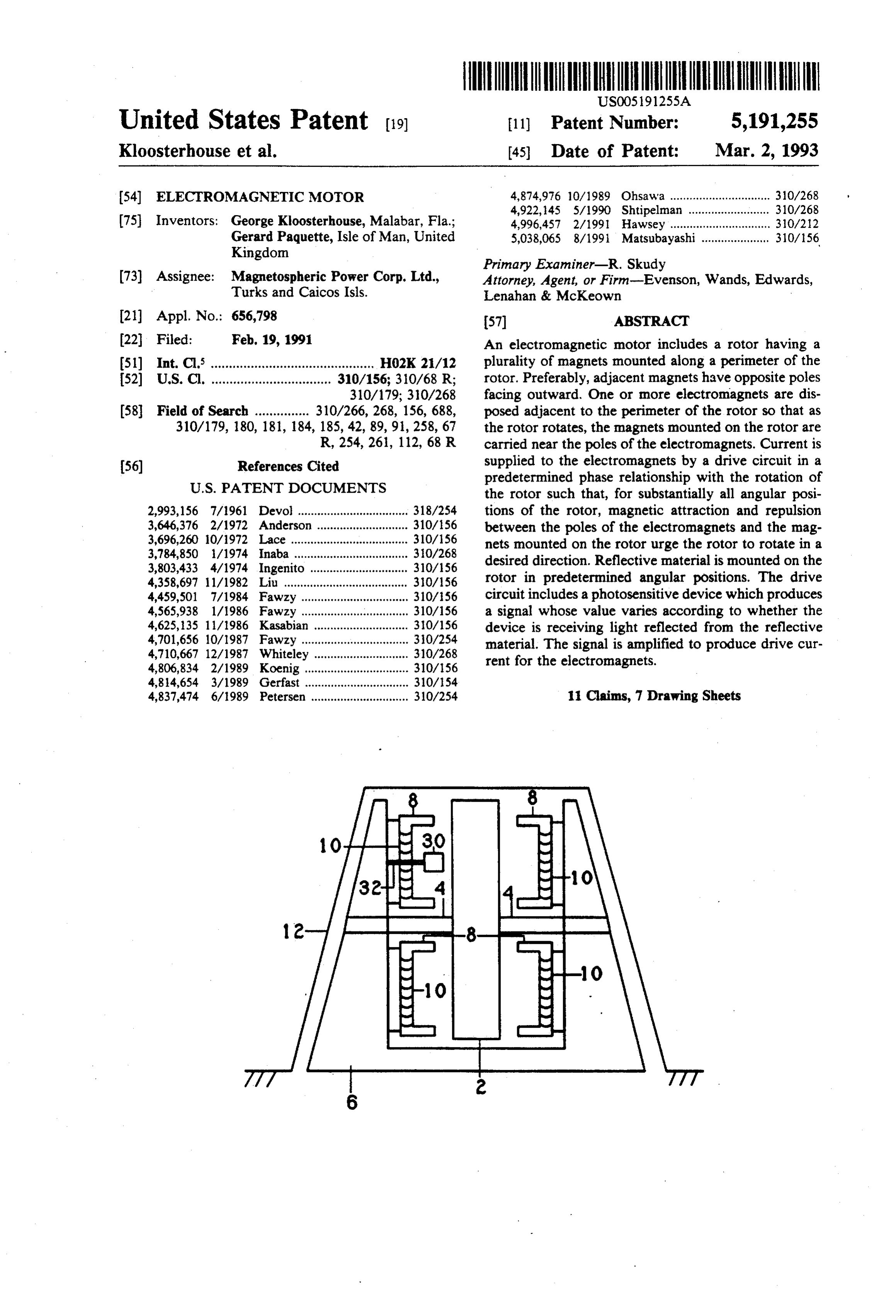
electromagnets 8 are shown in FIG. 1, any suitable
ELECTROMAGNETIC MOTOR number may be employed. Also, while the electromag nets 8 may all be disposed on a same side of the rotor 2,
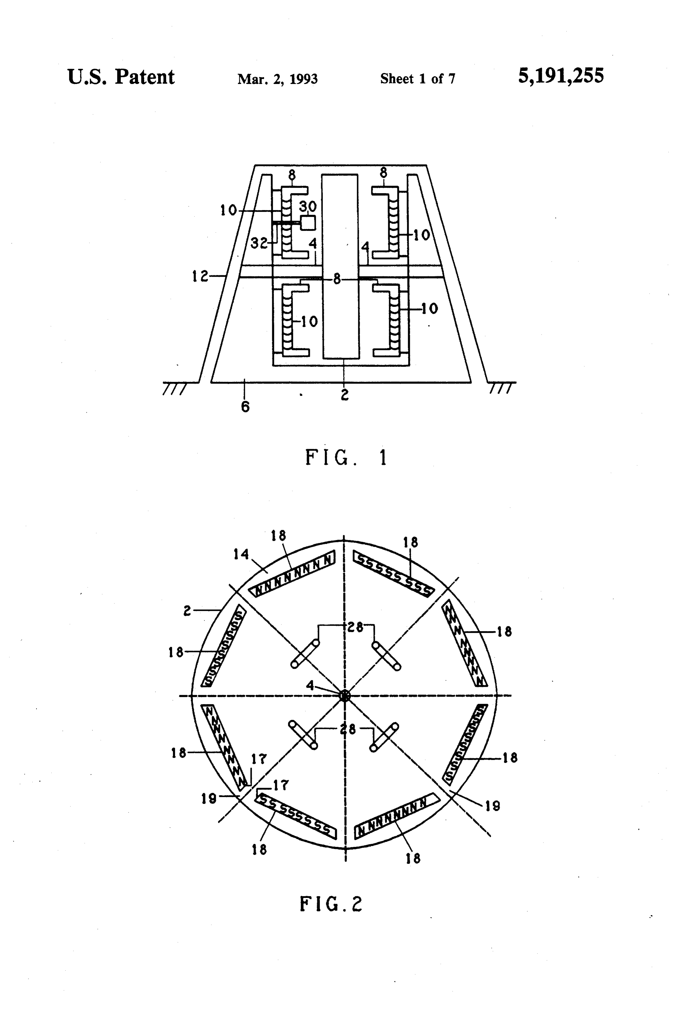
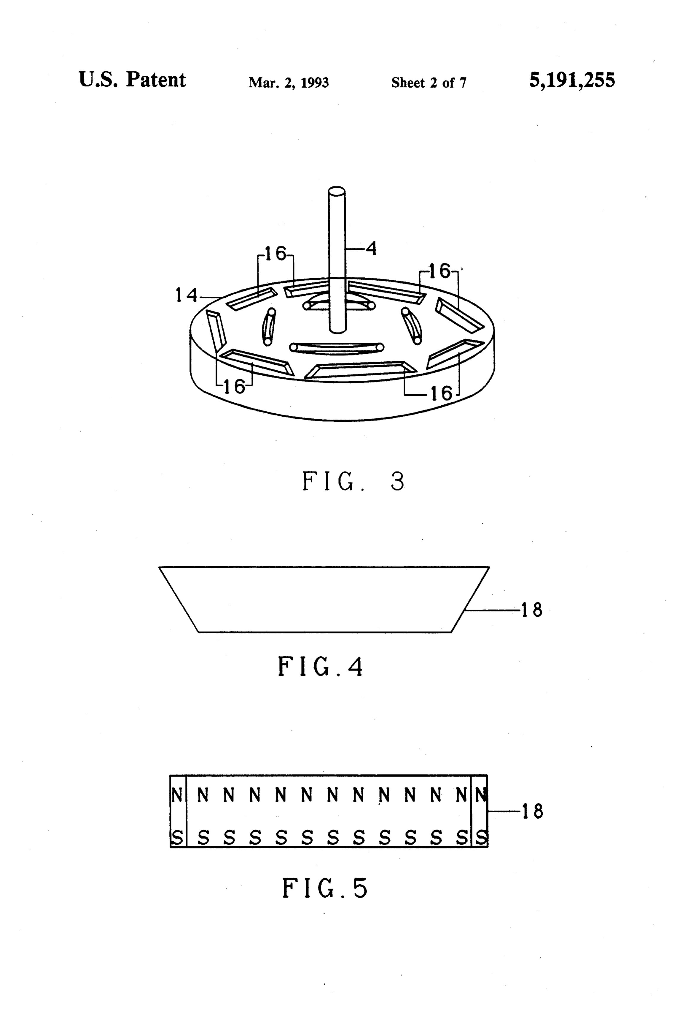
BACKGROUND AND SUMMARY OF THE in the present embodiment in FIG. 1, electromagnets 8 INVENTION are disposed on either side of the rotor 2. In a preferred This invention relates to the field of electromagnetic embodiment, the electromagnets are U-shaped. Coils 10 motors, and specifically to electromagnetic motors in are wound around the electromagnets 8. As will be which rotors having permanent magnets mounted described in detail below, suitable electric current is thereon are rotated by means of alternating phase cur 10 provided to the coils 10 to cause magnetic fields to be rents supplied to electromagnet stators. induced in the electromagnets 8. Depending on the An object of the invention is to provide mechanical direction of the current through a coil 10, a given end of motive power. An additional object of the invention is an electromagnet 8 may be either a north pole or a south to provide high speed mechanical motive power, pole. A grounded shield 12 may be employed to enclose wherein electrical input power consumption is reduced 5 the entire apparatus. , as mechanical speed of rotation increases. FIGS. 2 and 3 show a more detailed view of the rotor In order to realize these and other objectives, an 2 according to a first preferred embodiment of the in apparatus in accordance with the invention is provided vention. FIG. 2 shows a side view of the rotor 2, and comprising a rotor having a perimeter, a plurality of FIG.3 shows a perspective view of the rotor 2. Around magnets mounted on the perimeter of the rotor, an a perimeter 14 of the rotor 2, a plurality of slots 16 are electromagnet disposed adjacent to the perimeter of the provided. In the preferred embodiment, the slots are motor, and means for magnetizing the electromagnet arranged around the perimeter 14 end-to-end to suggest and for changing a polarity of the electromagnet in a the shape of a polygon. In the illustrated embodiment, 8 predetermined phase relationship with rotation of the slots are shown, thus suggesting the shape of an octa rotor, whereby magnetic attraction and repulsion be gon. As may be seen more clearly in the illustration of tween the electromagnet and the plurality of magnets 25 FIG. 3, the slots extend partly through the rotor 2. The cause the rotor to rotate. slots accommodate permanent magnets which are BRIEF DESCRIPTION OF THE DRAWINGS mounted to the rotor 2 and rotate therewith. Preferably the slots 16 may be trapezoidal in shape.
Other objects, advantages and novel features of the present invention will become apparent from the foll 30 of FIGS. a 4 and 5 show top and side views, respectively, permanent magnet 18 which may be inserted in the lowing detailed description of the invention when con slots 16. The magnet sidered in conjunction with the accompanying draw The top view as shownis shaped in FIG. as a trapezoidal prism.
4, shows a trapezoidal ings, in which: shape. In FIG. 4, the top and bottomb undaries of the FIG. 1 is a front view of an apparatus according to magnet are parallel, and the left and right sides are
slightly farther apart at the top than
FIG. 2 is a side view of a rotor used in the apparatus Accordingly, as shown more clearly in FIG. 2, at the bottom. of FIG. 1; the a series
FIG. 3 is a perspective view of the rotor of FIG. 2; the rotor 2. running end-to-end around the perimeter 14 of FIG. 4 is a top view of a magnet used in the rotor of While trapezoidal shapes are shown, other shapes
FIG. 5 is a side view of the magnet of FIG. 4; may be employed. For instance, the magnets may be in FIG. 6 is a perspective view of a magnet, a mounting a standard rectangular shape. Generally, it is preferred apparatus, and a portion of a rotor in accordance with that the magnets 18 have two elongated opposing faces the second embodiment of the invention; which serve as magnetic poles. The magnets are in FIG. 7 is a schematic diagram of a circuit for produc 45 serted into the slots 16 or otherwise mounted onto the ing signals for energizing the electromagnets of the rotor 2 such that a desired one of the poles faces out apparatus of FIG. 1; ward. Thus, a magnetic dipole axis running through the FIG. 8 is a schematic diagram showing the electro two poles of one of the magnets 18 will be approxi magnets of the apparatus of FIG. 1, along with addi mately parallel to an axis of rotation of the rotor 2. Also, tional circuitry for driving the electromagnets; while eight magnets 18 on each side of the rotor 2 are FIGS. 9-11 show a portion of an apparatus according shown, the number of magnets 18 used may vary de to the invention in operation at three successive points pending ture.
on factors such as the size of the overall struc in time;
FIG. 12 is a side view of a rotor in accordance with As will be described below, magnetic attraction and another embodiment of the invention; and 55 repulsion between the magnets 18 and the electromag FIG. 13 is a perspective view of an apparatus accord nets 8 produce a push-pull effect which causes the rotor ing to the invention including the rotor of FIG. 12. 2 to rotate in a desired direction, either clockwise or
DETAILED DESCRIPTION OF THE
counterclockwise. The longer the magnets 18 are from end-to-end, the longer the duration of each push and
INVENTION each pull. Thus, the power of the electromagnetic FIG. 1 shows a front view of an apparatus according motor according to the invention is related to the length to the invention. A disk-shaped rotor shown in an edge of the magnets 18. In the preferred, embodiment, eight view, is supported by and rotates about an axle 4. The or the magnets 18 are disposed in a generally end-to-end rotor 2 is preferably made of a non-magnetically con fashion around the perimeter of the rotor 2, so each ductive material such as a neodymium iron boron alloy. 65 magnet 18 has a length proximately corresponding to The axle 4 is supported in a base 6 at its ends. One or 45' of the circumference of the rotor 2, but with a spac more electromagnets 8 are mounted by suitable means ing 19 between adjacent ends 17 of a adjacent magnets, so that they are disposed near the rotor 2. While four as shown in FIG. 2. However, a different number of
Page 10
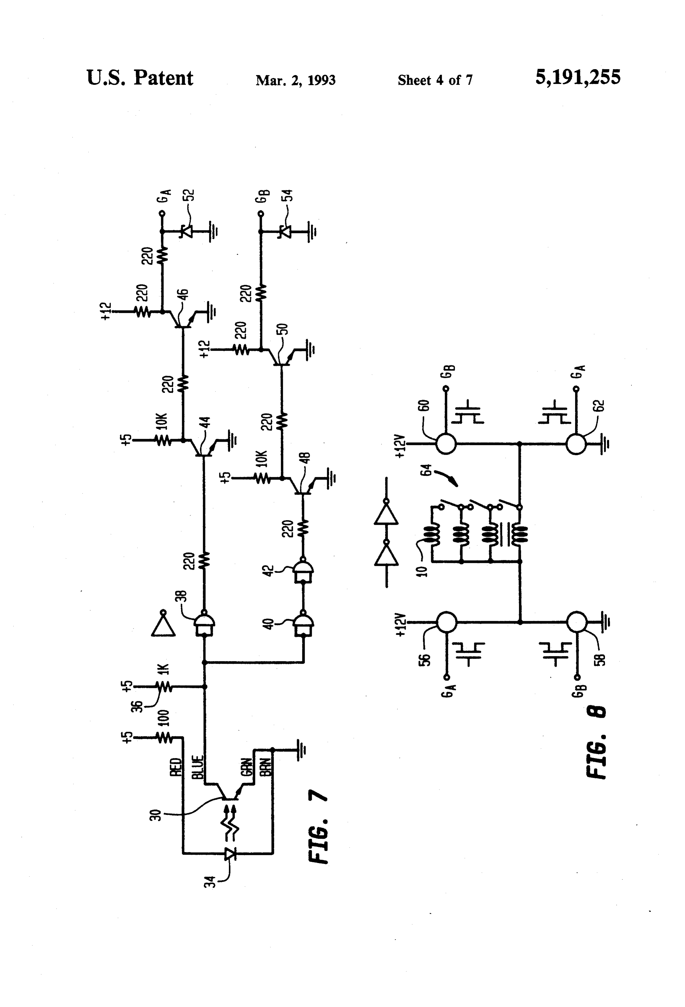
magnets could be similarly employed. For instance, six Turning now to FIG. 7 there is shown a schematic magnets disposed end-to-end around the perimeter of diagram of a drive circuit including the photosensitive the rotor suggesting the shape of a hexagon could be device 30 of FIG. 1, and additional circuitry for provid used. In such an embodiment, each magnet 18 would ing drive current to the coils 10 of the electromagnets 8. have a length corresponding to 60 of the circumfer The photosensitive device 30 is shown as a phototran ence of the rotor 2. The power of such a device would sistor which conducts current according to the amount be correspondingly increased relative to a device hav of light which impinges on it. A light emitting diode ing eight magnets. (LED) 34 is mounted adjacent to the phototransistor 30. Returning to FIG. 5, it will be seen that each trape The LED 34 may also be mounted on the supporting zoidal face of the trapezoidal prism is a pole of the means 32 shown in FIG. 1, or may be otherwise sup magnet 18. FIG. 5 shows that the upper portion of the ported. The LED 34 directs a beam of light against the magnet is the north pole. The letter N is repeated along surface of the rotor 2. During time intervals when the the length of the view of FIG. 5 to indicate that the reflective material 28 is adjacent to the phototransistor upper portion, in its entirety, is the north pole. Simi 30 and the LED 34, the light is reflected onto the photo larly, the lower portion of the view of FIG. 5 is the transistor 30, causing it to conduct current. A resistor 36 south pole. Since FIG. 4 is a top view and FIG. 5 is a is connected between a power supply voltage and the side view of the magnet 18, it will be understood that collector of the phototransistor 30. Accordingly, a volt the view of FIG. 4 is an end-on view of the north pole. age at the collector of the phototransistor 30 varies In accordance with the invention, magnets 18 are in between high and low values depending on whether light from the LED 34 is reflecting off a portion of the serted in the slots 16 such that the outward facing sur reflective material 28.
face of any given magnet, in its entirety, is one pole of the magnet. The inner facing surface is the other pole of ofThe logic collector of the transistor 30 is coupled to inputs gates 38, 40. The logic gate 40 has an output the magnet.
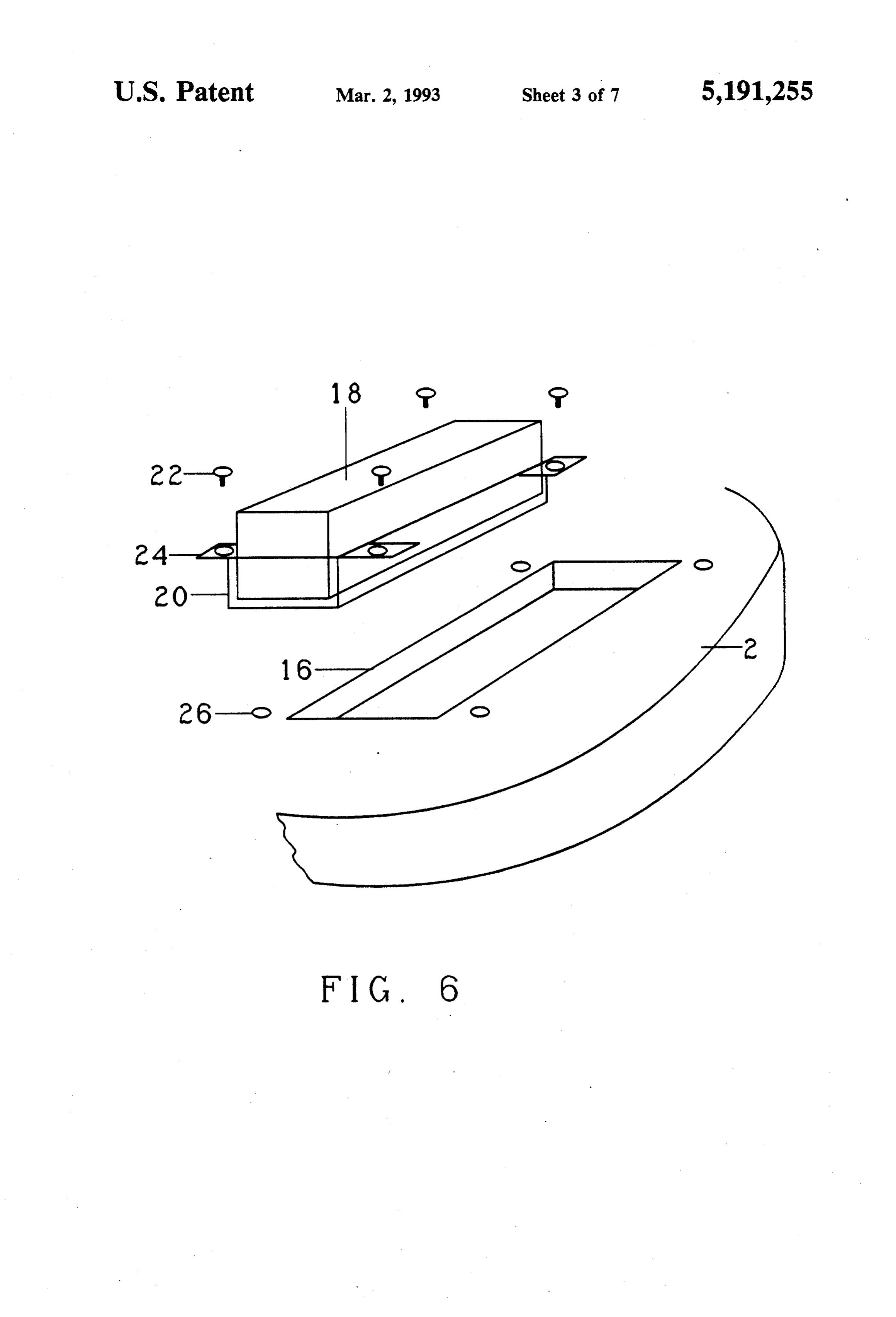
FIG. 6 shows a partial exploded view of a portion of 25 logic gatescoupled which is to an input of a logic gate 42. The the rotor 2 according to a second embodiment of the gates. It is common42,practice 38, 40, are shown as two-input NAND to employ a multi-input invention. A permanent magnet 18 substantially similar inverted-output gate such as a two-input NAND gate as to that of FIGS. 4 and 5 is bonded to a tray 20. The tray an inverter by coupling an input signal to all of the 20 accommodates fasteners 2 for removably fastening inputs and the NAND gate. While a wide variety of the tray20 to the rotor 2. In the embodiment in FIG. 6, logic devices may be used in place of the logic gates 38, the fasteners 22 are screws. A slot 16 is provided for 40, 42, the objective here is to provide two output sig accommodating the magnet 18 inside the tray 20. How nals which follow the collector of the phototransistor ever, the slot 16 may be omitted if a flush mounted tray 30 and which are in opposite logic states. is employed. In the illustrated embodiment, the fasten Outputs of the logic gates 38,42 are coupled to ampli ers 22 are inserted through holes in tabs 24 on the tray fiers. Each amplifier is shown as having two transistor 20 to holes 26 in the rotor 2. The holes 26 may have stages. The amplifier coupled to the output of the logic screw threads. Accordingly, a magnet bonded to a tray gate 38 includes transistors 44, 46, and the amplifier may be quickly and easily removed or replaced. coupled to the output of the logic gate 42 includes the Returning to FIG. 2, it will be noted that, in the transistors 48, 50. Outputs of the amplifiers at the collec preferred embodiment, magnets 18 are inserted in the tors of the transistors 46 and 50 are coupled through slots of the rotor 2 (or otherwise mounted) such that, in resistors to cathodes of Zener diodes 52, 54, respec sequence around the perimeter 14, alternating poles are tively. The Zener diodes 52, 54 are coupled such that, facing outward. when a high voltage is received from the transistors 46 FIG. 2 also shows a plurality of regions on the sur or 50, the Zener diodes will be reverse biased, and will face of the rotor 2 which bear reflective material 28. thus serve as voltage regulators in accordance with The reflective material 28 is preferably disposed at a their reverse bias breakdown voltages. Outputs of the radial distance from the axis 4 such that, as the rotor 2 circuit of FIG. 7 are shown as G4 and GB respectively. rotates, at a given fixed position relative to the axis 4, Signals appearing at these outputs vary between high alternating regions of reflective material and regions and low voltage states in accordance with whether a lacking reflective material on the rotor 2 are adjacent to piece of reflective material 28 is adjacent to the photo the given position. The reflective material 28 may be transistor 30.
used in conjunction with a photosensitive device for . FIG. 8 is a schematic representation of the coils 10 of determining an angular position of the rotor 2. the electromagnets 8. Additional drive circuitry is FIG. 1 shows in schematic form, a photosensitive shown, which is coupled to receive the voltages G4 and device 30 which is supported by a suitable supporting GB from the circuit of FIG. 7. The drive circuit pro means 32 mounted to the frame 6, such as a bracket or vides current to the coils 10. The direction of the cur arm. The photosensitive device 30 may be a photocell, rent through the coils 10 is determined by which of the photodiode, phototransistor, or other suitable elec signals Ga or Gb is high.
tronic device. As the rotor 2 rotates, an output signal The portion of the drive circuit shown in FIG. 8 from the photosensitive device 30 will vary between includes four power MOSFETs (metal oxide-semicon two different values, depending upon whether a portion ductor field effect transistors) 56, 58, 60, 62. As shown, of the reflective material 28 is adjacent to the photosen drains of the power MOSFETs 56,60 are coupled to a sitive device 30. The output signal may be employed to power supply, which produces a suitable supply volt control the polarity of current supplied through the age, such as 12, 24 or 36 volts, and sources of the power coils 10 to the electromagnets 8, as described below. MOSFETs 58, 62 are coupled to ground. Sources of the The output signal may also be used for other suitable power MOSFETS 56, 60 are coupled to drains of the purposes such as for providing an input signal to a ta power MOSFETS 58, 62, respectively. The source of chometer. the power MOSFET 56 is also coupled to a first end of
Page 11
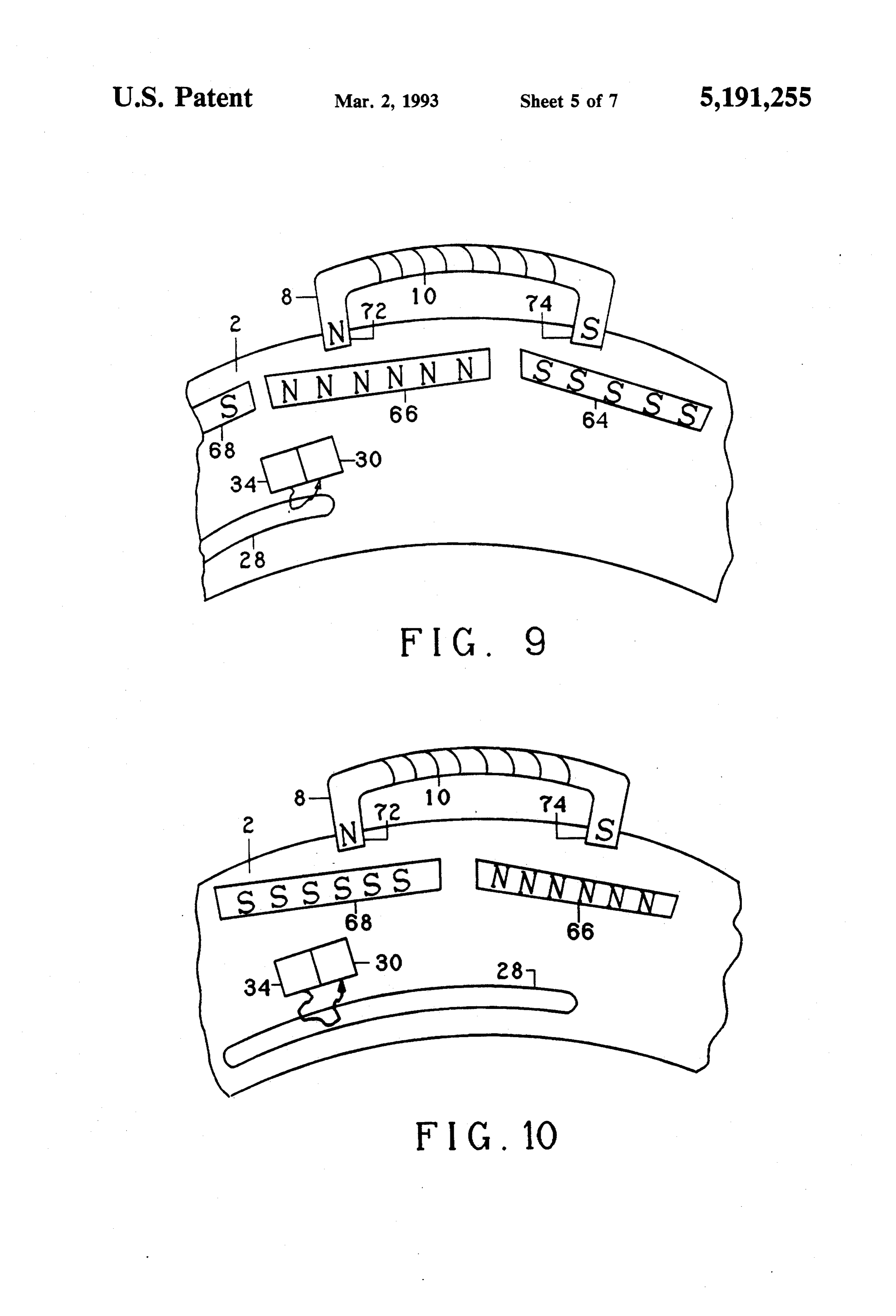
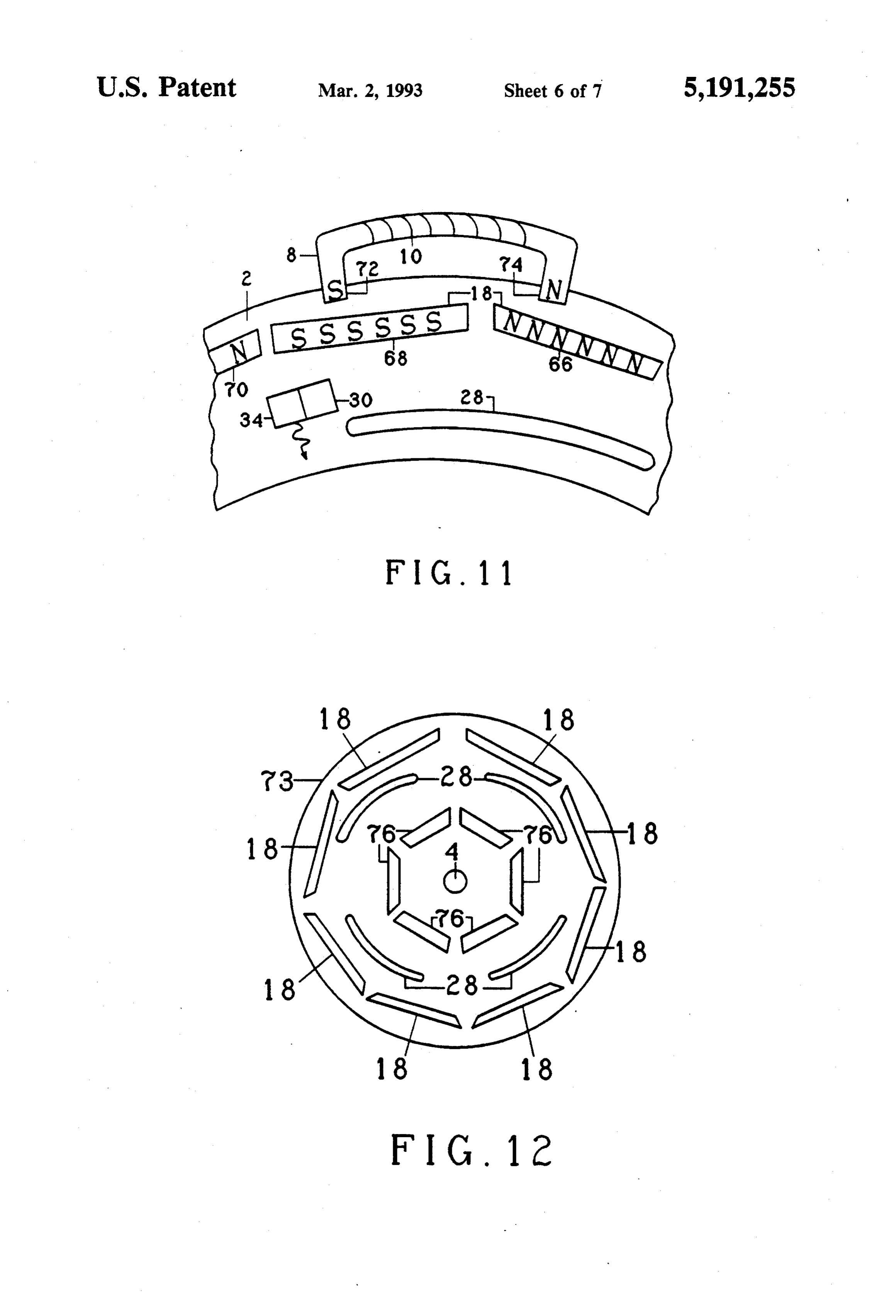
each of the coils 10. The coils 10 are coupled in parallel, Turning now to FIG. 10, a small amount of time has as shown. Switches collectively labeled as 64 are pro elapsed. The magnet 66 has partially overtaken the pole vided between the second ends of each of the coils 10 so 74 due to clockwise rotation of the rotor 2. The beam of that one or more of the coils 10 may be disconnected light from the LED 34 continues to impinge on the from the circuit by opening the appropriate switch 64. reflective material 28, causing light to strike the photo Thus, certain ones of the coils may normally be left sensitive device 30. As a consequence, current flowing disconnected, but may be connected as necessary to through the coil 10 is traveling in the same direction as provide extra power. The second end of the first coil before, and the poles 72 and 74 remain north and south, and of an subsequent coils 10 coupled by means of these respectively. There is magnetic attraction between the switches 64 are coupled to the source of the power 10 poles 74 and the magnet 66. Since the pole 74 is to the MOSFET 60. right of center of the magnet 66, magnetic attraction When a reflective material 28 is adjacent to the pho urges the rotor 2 to rotate clockwise. Similarly, mag totransistor 30, GA is high and GB is low. Accordingly, netic attraction between the magnet 68 and the first pole current flows from the drain to the source of the power 15 72 also urges clockwise rotation. MOSFET 56, through the coils 10, from the drain to the Turning now to FIG. 11, another brief time interval source of the power MOSFET 62, to ground. The has elapsed. The poles 72 and 74 are now to the left of power MOSFETs 58, 60 do not conduct current at this center of the magnets 68 and 66, respectively. If current time. When a non-reflective area is adjacent to the pho were still flowing in the coil 10 in the same direction as totransistor 30 G4 is low and GB is high. Accordingly, 20 before, then the pole 72 would still be a north pole and current flows from the power supply from the drain to the pole 74 would still be a south pole. Since these poles the source of the power MOSFET 60, through the coils are to the left of center of the respective permanent 10, from the drain to the source of the power MOSFET magnets, magnetic attraction and repulsion would cause 58, to ground. In this latter situation, current flows a braking effect or urge counterclockwise rotation of through the coils 10 in the opposite direction as in the 25 the rotor 2.
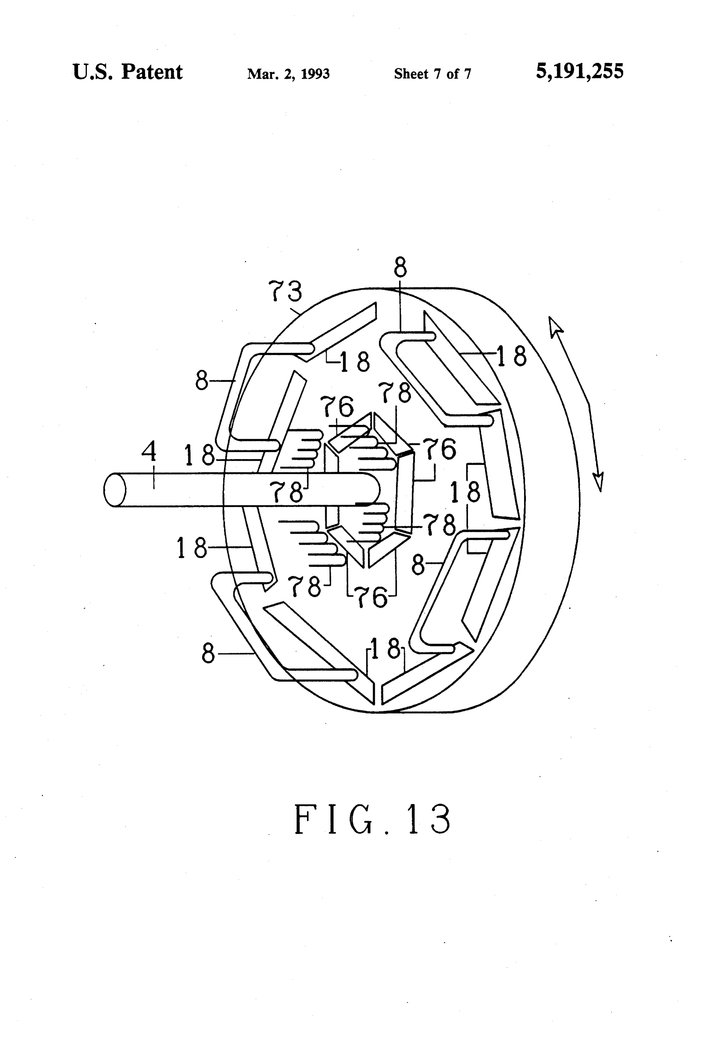
former case. Accordingly, the polarity of the electro However, in accordance with the invention the beam magnets 8 is reversed. of light from the LED 34 has passed beyond the end of The operation of a preferred embodiment of the in the reflective material 28. The beam of light thus is no vention will now be described in detail with respect to longer being reflected onto the photosensitive device FIGS. 9, 10, and 11. In these three figures, three states 30 30. By operation of the circuits of FIGS. 7 and 8, cur of operation of the device are illustrated in chronologi rent now flows in the opposite direction through the cal order. Throughout, the electromagnet 8 is shown in coil 10 as before. The pole 72 is now a south pole, and a stationary position Also, the LED 34 and the photo the pole 74 is now a north pole. In accordance with the sensitive device 30 are shown schematically in a fixed prior description of FIGS. 9 and 10, magnetic repulsion position. Relative to these stationary devices, the rotor 35 between the south pole 72 and the south pole of the 2 is shown rotating. Permanent magnets rotate along magnet 68 urges the rotor 2 to rotate clockwise. Simi with the rotor 2. In FIGS. 9-11, the rotor 2 is rotating larly, magnetic attraction between the south pole 72 and clockwise. Accordingly, FIG. 9 occurs first in time, north poles of magnets 66 and 70 also urges the rotor 2 FIG. 10 occurs slightly thereafter, and FIG. 11 occurs to rotate clockwise. The same is true for the pole 74. slightly after that. While this illustration showed the rotor rotating In FIG. 9, the rotor 2 is carrying magnets shown clockwise, it will be understood that devices in accor specifically as 64, 66, and 68 past poles of the electro dance with the invention could be designed to rotate magnet 8. The rotation of the rotor 2 also has carried a counterclockwise. For such an alternative device, piece of reflective material 28 mounted on the rotor 2 drawings suitably altered, such as by mirror image, into the path of a beam of light emitted by the LED 34. 45 from FIGS. 9-11 would illustrate its operation. An The light reflects off the reflective material 28 and apparatus in accordance with the invention may be strikes the photosensitive device 30. In accordance with employed for generating electric current, as well as for the operation of the circuits of FIGS. 7 and 8, current producing mechanical motive power. In FIG. 12, there flows through the coils 10 on the electromagnet 8 such is shown a rotor 73, similar to that of FIG. 2, but further that a first hole 72 is a north pole and a second pole 74 including additional magnets 76. The magnets 76 may is a south pole. As shown in FIG. 9, the first pole 72 be of an essentially similar type to the magnets 18, and (north) is to the left of center of the permanent magnet may be mounted similarly on the rotor 2. Preferably, the 66 The north pole of the permanent magnet 66 is facing magnets 76 are disposed closer to the axle 4 than the outward, adjacent to the pole 72 of the electromagnet 8. magnets 18. As will be described below, the magnets 76 Accordingly, magnetic repulsion is taking place be 55 are used for generating electric power. Since torque is tween the magnet 66 and the pole 72. Since the pole 72 applied to the rotor 2 by magnetic forces between the is to the left of center, magnetic repulsion between 72 magnets 18 and the electromagnets 10 as described and the magnet 66 urges the magnet 66 and, hence, the above, positioning the magnets 76 relative close to the rotor 2 to rotate clockwise. Also, the pole 72 is farther axle 4 facilitates generating electric power. away from the magnet 64 than it is from the magnet 68. Referring to FIG. 13, there is shown a perspective The two magnets both have south poles both facing view of the rotor 73 of FIG. 12. Magnets 18 and electro outward. Since the pole 72 is closer to the magnet 68 magnets 8 similar to those of the previously described than it is to the magnet 64, magnetic attraction between embodiments are shown. To simplify the drawing, the the pole 72 and the magnet 68 also urges the rotor to strips of reflective material 28 have been omitted, but it rotate clockwise. Through a similar analysis, it will be 65 will be understood that they are present in essentially seen that magnetic attraction and repulsion involving similar configurations to those shown in FIG. 12. The the pole 74 of the electromagnet also urges clockwise magnets 76 are also shown forming a series end-to-end rotation. around the axle 4, as shown in FIG. 12.
Page 12
It will also be understood that magnets 18 and 76, ent angular positions. Such an embodiment might oper strips of reflective material 28, electromagnets 8, and ate to cause current to flow through the coil 10 in one other components on or adjacent to the visible face of direction part of the time, in a second direction part of the rotor 73 in FIGS. 12 and 13 may also be on the the time, and not all part of the time. The embodiment opposite face of the rotor 73, although that face is not in could be employed in order to accommodate foresee view in FIGS. 12 and 13. As the rotor 73 rotates under able variations and dimensions of the electromagnet 8 the influence of magnetic attraction and repulsion be and the permanent magnets.
tween the electromagnets 8 and the permanent magnets Thus, reviewing the respective electromagnetic 18, the magnets 76 rotate as well. In order to produce motor and combined electromagnetic motor and gener electric power, there is provided a plurality of coils 78, 10 ator embodiments of the present invention, described which are show in schematic form. The coils 78 are above with reference to FIGS. 1-13, an electromag mounted by a suitable means to be positioned adjacent netic motor in accordance with an embodiment of the to the magnets 76. Thus, as the magnets 76 rotate along present invention comprises a generally disc-shaped with the rotor 73, by Faraday's law electric current is rotor 2 mounted for rotation about an axis/axle 4. A induced in the coils 78. Six magnets 76 and four coils 78 15 plurality of generally elongate permanent magnets 18 are shown in the side of the rotor 73 visible in FIG. 12. are mounted (via slots 16) on the rotor in a generally It will be understood, however, that magnets 76 and end to end arrangement, so as to form a generally po coils 78 may be disposed on the other side of the rotor lygonal distribution of permanent magnets about the 73 as well. Also, the number and configuration of the axis 4. A first elongated face of each of the permanent magnets 76 and the coils 78 may vary within the spirit 20 magnets 18 has a north magnetic polarity and a second and scope of the invention. The coils 78 may be any elongated face of each of the permanent magnets has a suitable structure for inducing current from a moving south magnetic polarity. Within the generally polygo magnetic field. For instance, the coils 78 could be struc nal distribution of the magnets of the plurality, alternate tures similar to the electromagnets 8. ones of the permanent magnets have their first faces of In summary, in accordance with the invention, the 25 north magnetic polarity facing outwardly from the reflective material 28 is disposed on the rotor 2 in posi rotor, and alternate others of the permanent magnets, tions such that reflection or non-reflection of the beam which are located between the alternate ones of the of light from the LED 34 causes current to flow permanent magnets, have their second faces of the through the coils 10 to cause clockwise rotation of the south magnetic polarity facing outwardly from the rotor 2 in a desired direction. It will be understood to 30 rotor, as shown diagrammatically in FIG. 2, for exam one of ordinary skill in the art that the exact number and ple. As a result, as one proceeds around the generally dimensions of permanent magnets, the exact dimension polygonal distribution of the plurality of permanent of the electromagnets 8, the position of the LED 34 and magnets, one successively encounters an alternating the photosensitive device 30, and the disposition of the distribution of north and south faces of the plurality of reflective material 28 on the rotor 2 may all vary within 35 generally elongate permanent magnets 18. the spirit and scope of the invention. It is to be under A plurality of electromagnets 8 are supported with stood that those permutations of these parameters respect to the rotor 2, such that at least one pole of a which, in combination, provide the ultimate result of a respective electromagnet 8 is disposed adjacent to the net urging of the rotor in a desired direction for the generally polygonal distribution of the plurality of gen preponderance of angular positions of the rotor 2 shall erally elongate permanent magnets 18 that are mounted fall within the metes and bounds of the invention. on the rotor. As described above with respect to FIGS. For example, it may be that in alternative embodi 9, 10 and 11, and as shown in FIG. 13, the plurality of ments, the angular distance between the poles 72 and 74 electromagnets 8 are arranged such that, as the rotor of a typical U-shaped electromagnet may not corre rotates about its axis, whenever a respective one of the spond exactly to the angular dimensions of one of the 45 permanent magnets 18 becomes juxtaposed with a pole permanent magnets on the rotor 2. In such an alterna of a respective electromagnet 8, both the magnetic po tive embodiment, for instance, the pole 72 of the elec larity of the pole of the respective electromagnet is tromagnet may be exactly centered on a magnet such as maintained and only the pole of the respective electro the magnet 66, while, due to differing dimensions, the magnet is juxtaposed with the respective one of the pole 74 is to the right or to the left of center of the permanent magnets during the entirety of travel of the adjacent magnet, such as 64. In such a situation, analysis respective one of the permanent magnets past the pole might show that for certain ranges of angular displace of the respective electromagnet. Upon completion of ment of the rotor 2, a given polarity of the electromag travel of the respective one of the permanent magnets net 8 might urge rotation of the rotor in one direction, past the pole of the respective electromagnet, the mag while for other ranges of angular displacement rotation 55 netic polarity of the respective electromagnet is in the opposite direction might be urged. It would be changed to an opposite magnetic polarity, in association understood from the foregoing that alternative arrange with the one pole of the respective electromagnet be ments, such as alternative placement of the reflective coming juxtaposed with a respective another of the material 28, of the LED 34 and the photosensitive de permanent magnets, an outwardly facing elongated face vice 30, etc., may be taken in order to provide the de 60 of which has a magnetic polarity opposite to the mag sired result of a net urging of the rotor 2 in the desired netic polarity of the outwardly facing elongated face of direction for the preponderance of angular positions of the respective one of the permanent magnets. the rotor 2. As another alternative embodiment, two The electromagnetic motor in accordance with the LEDS 34 and photosensitive devices 30 could be pro present invention also includes an electromagnet energi vided, for instance being disposed onto concentric por 65 zation circuit, shown in detail in FIG. 8, which is cou tions of the rotor 2. In such an alternative embodiment, pled to the plurality of electromagnets and is operative pieces of reflective material 28 could be positioned on to controllably supply energizing current to the plural the different concentric portions of the rotor 2 at differ ity of electromagnets such that poles thereof which are
Page 13
juxtaposed to respective ones of the permanent magnets lygonal distribution of permanent magnets about the are of the same magnetic polarity of the juxtaposed rotor axis. The second generally polygonal distribution permanent magnets, so as to cause magnetic repulsion of permanent magnets 76 is closer to the axis of the of juxtaposed permanent magnets and thereby drive the rotor 73 than the first generally polygonal distribution rotor about its axis. of permanent magnets 18, as shown in FIG. 13. A first In accordance with the embodiment of the invention, elongated face of each permanent magnet 76 of the shown in FIG. 13, both an electromagnetic motor and second plurality has a north magnetic polarity and a generator are provided in the same apparatus. The com second elongated face of each the permanent magnets bined electromagnetic motor and generator comprises a of the second plurality has a south magnetic polarity. rotor 73 mounted for rotation about an axis 4. A first 10 Within the second generally polygonal distribution of plurality of generally elongate permanent magnets 18 permanent magnets, alternate ones of the permanent are mounted on the rotor in a generally end to end magnets of the second plurality have their first faces of arrangement, so as to form a first generally polygonal north magnetic polarity facing outwardly from the distribution of permanent magnets about the axis. A first rotor and alternate others of the permanent magnets of elongated face of each of the permanent magnets 18 has 15 the second plurality, which are located between alter a north magnetic polarity and a second elongated face nate ones of the permanent magnets of the second plu of each of the permanent magnets has a south magnetic rality, have their second faces of south magnetic polar polarity. Within the first generally polygonal distribu ity facing outwardly from the rotor. As a result, as one tion of permanent magnets, alternate ones of the perma proceeds around the second generally polygonal distri nent magnets 18 have their first faces of north magnetic 20 bution of permanent magnets, one successively encoun polarity facing outwardly from the rotor and alternative ters an alternating distribution of north and south faces others of the permanent magnets, which are located of the second plurality of generally elongate permanent between the alternate ones of the permanent magnets, magnets.
have their second faces of south magnetic polarity fac A plurality of electromagnetically responsive coils 78 ing outwardly from the rotor. As a result, as one pro 25 are supported with respect to the rotor 73, so as to be ceeds around the first generally polygonal distribution disposed adjacent to the second generally polygonal of the plurality of permanent magnets, one successively distribution of the plurality of permanent magnets 76 encounters an alternating distribution of north and that are mounted on the rotor. As the rotor rotates south faces of the plurality of generally elongate perma about its axis, the travel of the permanent magnets of the nent magnets. 30 second plurality past the plurality of electromagneti A plurality of electromagnets 8 is supported with cally responsive coils induces current flow in the coils, respect to the rotor 73, such that at least one pole of a so that electric power may be derived therefrom. respective electromagnet is disposed adjacent to the The system in accordance with the invention as de first generally polygonal distribution of generally elon scribed above would be capable of achieving a high gate plurality of permanent magnets that are mounted 35 speed of rotation of the rotor 2. The apparatus would be on the rotor. The plurality of electromagnets 8 are ar "closed loop' system in that changes in the current flow ranged such that, as the rotor rotates about is axis, through the coil 10 to produce changes in the polarity whenever a respective one of the permanent magnets 18 of the electromagnet 8 would result from angular dis becomes juxtaposed with a pole of a respective electro placement of the rotor 2. During a time interval in magnet 8, both the magnetic polarity of the pole of the which the photosensitive device 30 either is or is not respective electromagnet is maintained and only the receiving light, current will continuously flow through pole of the respective electromagnet is juxtaposed with the coils 10. The direction of flow depends on whether the respective one of the permanent magnets during the the device 30 is receiving the light. By contrast, during entirety of the travel of the respective one of the perma time intervals when the beam of light from the LED 34 nent magnets past the pole of the respective electromag 45 passes from a region of reflective material 28 to a region net. Upon completion of the travel of the respective one in which there is no such material or visa versa, transi of the permanent magnets past the pole of the respective tions will take place in which current flow through the electromagnet, the magnetic polarity of the respective coil 10 is momentarily stopped. The faster the speed at electromagnet is changed to an opposite magnetic po which the rotor 2 rotates, the more frequently such time larity, in association with the one pole of the respective intervals will take place. Accordingly, overall system electromagnet becoming juxtaposed with a respective power consumption will tend to go down as the speed another of the permanent magnets, the outwardly fac of rotation of the rotor 2 increases.
ing elongated face of which has a magnetic polarity Although the invention has been described and illus opposite to the magnetic polarity of the outwardly fac trated in detail, it is to be clearly understood that the ing elongated face of the respective one of the perma 55 same is by way of illustration and example, and is not to nent magnets. be taken by way of limitation. The spirit and scope of An electromagnet energization circuit, such as shown the present invention are to be limited only by the terms in FIG. 8 described above, is coupled to the plurality of of the appended claims.
electromagnets 8 and is operative to controllably supply What is claimed is:
energizing current to the plurality of electromagnetics, 60 1. An electromagnetic motor comprising: such that poles thereof which are juxtaposed to respec a rotor mounted for rotation about an axis; tive ones of the permanent magnets have the same mag a plurality of generally elongate permanent magnets netic polarity of the juxtaposed permanent magnets, so mounted on said rotor in a generally end to end as to cause magnetic repulsion of juxtaposed permanent arrangement, so as to form a generally polygonal magnets and thereby drive the rotor about its axis. 65 distribution of said permanent magnets about said A second plurality of generally elongate permanent axis, a first elongated face of each of said perma magnets 76 is mounted on the rotor in a generally end to nent magnets having a north magnetic polarity and end arrangement, so as to form a second generally po a second elongated face of each of said permanent
Page 14
magnets having a south magnetic polarity, and bution thereof on said rotor, such that the first and wherein, within the generally polygonal distribu second poles of said respective electromagnet are re tion of the magnets of said plurality, alternate ones spectively juxtaposed with successively adjacent ones of said permanent magnets have their first faces of of said permanent magnets.
said north magnetic polarity facing outwardly 5 4. An electromagnetic motor according to claim 3, from said rotor and alternate others of said perma wherein the magnetic polarity of said pole of said re nent magnets, which are located between said al spective electromagnet is controlled so as to be the same ternate ones of said permanent magnets, have their as the magnetic polarity of the outwardly facing elon second faces of said south magnetic polarity facing gated face of a respective permanent magnet that is outwardly from said rotor, so that, as one proceeds 10 juxtaposed therewith.
around said generally polygonal distribution of said 5. An electromagnetic motor comprising: plurality of permanent magnets, one successively a generally disc-shaped rotor mounted for rotation encounters an alternating distribution of north and about an axis;
south faces of said plurality of generally elongate a first plurality of generally elongate permanent mag permanent magnets; 15 nets mounted on one side of said generally disc a plurality of electromagnets supported with respect shaped rotor in a generally end to end arrange to said rotor such that at least one pole of a respec ment, so as to form a generally polygonal distribu tive electromagnet is disposed adjacent to said tion of said permanent magnets about said axis, a generally polygonal distribution of said plurality of first elongated face of each of said first permanent generally elongated permanent magnets that are 20 magnets having a north magnetic polarity and a mounted on said rotor, and wherein said plurality second elongated face of each of said first perma of electromagnets are arranged such that as said nent magnets having a south magnetic polarity, and rotor rotates about said axis, whenever a respective wherein, within the generally polygonal distribu one of said permanent magnets becomes juxtaposed tion of the first permanent magnets of said first with a pole of a respective electromagnet, both a 25 plurality, alternate ones of said first permanent magnetic polarity of said pole of said respective magnets have their first faces of said north mag electromagnet is maintained and only said pole of netic polarity facing outwardly from said one side said respective electromagnet is juxtaposed with of said generally disc-shaped rotor and alternate said respective one of said permanent magnets others of said first permanent magnets, which are during the entirety of travel of said respective one 30 located between said alternate ones of said first of said permanent magnets past said pole of said permanent magnets, have their second faces of said respective electromagnet, and wherein, upon com south magnetic polarity facing outwardly from said pletion of the travel of said respective one of said one side of said generally disc-shaped rotor, so that, permanent magnets past said pole of said respective as one proceeds around said generally polygonal electromagnet, the magnetic polarity of said re 35 distribution of said first plurality of generally elon spective electromagnet is changed to an opposite gate first permanent magnets, one successively magnetic polarity, is association with said one pole encounters an alternating distribution of north and of said respective electromagnet becoming juxta south faces of said first plurality of generally elon posed with a respective another of said permanent gate permanent magnets;
magnets, an outwardly facing elongated face of 40 a second plurality of generally elongated second per which has a magnetic polarity opposite to the mag manent magnets mounted on a second side of said netic polarity of an outwardly facing elongated generally disc-shaped rotor, opposite to the one face of said respective one of said permanent mag side thereof in a generally end to end arrangement, nets; and so as to form a generally polygonal distribution of an electromagnet energization circuit coupled to said 45 said second permanent magnets about said axis, a plurality of electromagnets and being operative to first elongated face of each of said second perma controllably supply energizing current to said plu nent magnets having a north magnetic polarity and rality of electromagnets such that poles thereof a second elongated face of each of said second which are juxtaposed to respective ones of said generally elongate permanent magnets having a permanent magnets are of the same magnetic polar SO south magnetic polarity, and wherein, within the ity of the juxtaposed permanent magnets, so as to generally polygonal distribution of said plurality of cause magnetic repulsion of the juxtaposed perma second permanent magnets, alternate ones of said nent magnets and thereby drive said rotor about second permanent magnets have their first faces of said axis. said north magnetic polarity facing outwardly - 2. An electromagnetic motor according to claim 1, 55 from said second side of said generally disc-shaped wherein the magnetic polarity of said pole of said re rotor and alternate others of said second permanent spective electromagnetis controlled so as to be the same magnets, which are located between said alternate as the magnetic polarity of the outwardly facing elon ones of said second permanent magnets, have their gated face of a respective permanent magnet that is second faces of said south magnetic polarity facing juxtaposed therewith. outwardly from said second side of said generally 3. An electromagnetic motor according to claim 1, disc-shaped rotor, so that, as one proceeds around wherein a respective electromagnet comprises a gener said generally polygonal distribution of said plural ally U-shaped electromagnet having first and second ity of second permanent magnets, one successively poles of opposite magnetic polarities, said first and sec encounters an alternating distribution of north and ond poles being spaced apart from the one another by a 65 south faces of said plurality of generally elongate distance proximate to a separation between correspond second permanent magnets; ing locations of successively adjacent ones of said per a first plurality of first electromagnets supported with manent magnets within the generally polygonal distri respect to said one side of said generally disc
Page 15
shaped rotor such that at least one pole of a respec pluralities of electromagnets such that poles tive first electromagnet is disposed adjacent to said thereof which are juxtaposed to respective ones of generally polygonal distribution of said first plural said first and second permanent magnets, respec ity of first permanent magnets that are mounted on tively, are of the same magnetic polarity of the said one side of said generally disc-shaped rotor, 5 juxtaposed first and second permanent magnets, so and wherein said first plurality of first electromag as to cause magnetic repulsion of said juxtaposed nets are arranged such that as said generally disc first and second pluralities of first and second per shaped rotor rotates about said axis, whenever a manent magnets and thereby drive said generally respective one of said first permanent magnets disc-shaped rotor about said axis. becomes juxtaposed with a pole of said respective 10 6. An electromagnetic motor according to claim 5, first electromagnet, both the magnetic polarity of wherein the magnetic polarity of said pole of said re said pole of said respective first electromagnet is spective first or second electromagnet is controlled so maintained and only said pole of said respective as to be the same as the magnetic polarity of the out first electromagnet is juxtaposed with said respec wardly facing elongated face of a respective first or tive one of said first permanent magnets during 15 second permanent magniet that is juxtaposed therewith. entirety of travel of said respective one of said first 7. An electromagnetic motor according to claim 5, permanent magnets past said pole of said first re wherein a respective first or second electromagnet com spective first electromagnet, and whereon, upon prises a generally U-shaped electromagnet having first completion of the travel of said respective one of and second poles of opposite magnetic polarities, said said first permanent magnets past said hole of said 20 first and second poles being spaced apart from the one respective first electromagnet, the magnetic polar another by a distance proximate to a separation between ity of said first respective electromagnet is change corresponding locations of successively adjacent ones to an opposite magnetic polarity, in association of said first or second permanent magnets within the with said one pole of said respective first electro generally polygonal distribution thereof on a side of magnet becoming juxtaposed with a respective 25 said generally disc-shaped rotor, such that the first and another of said first permanent magnets, an out second poles of a respective first or second electromag wardly facing elongated face of which has a mag net are respectively juxtaposed with successively adja netic polarity opposite to the magnetic polarity of cent ones of said first or second permanent magnets. an outwardly facing elongated face of said respec 8. An electromagnetic motor according to claim 7, tive one of said first permanent magnets; 30 wherein the magnetic polarity of said pole of said re a second plurality of second electromagnets sup spective first or second electromagnet is controlled so ported with respect to said one side of said gener as to be the same as the magnetic polarity of the out ally disc-shaped rotor such that at least one pole of wardly facing elongated face of a respective first or a respective second electromagnet is disposed adja second permanent magnet that is juxtaposed therewith. cent to said generally polygonal distribution of said 35 9. An electromagnetic motor comprising: second plurality of generally elongate second per a rotor mounted for rotation about an axis; manent magnets that are mounted on said one side a first plurality of generally elongate permanent mag of said generally disc-shaped rotor, and wherein nets mounted on said rotor in a generally end to said second plurality of generally elongate second end arrangement, so as to form a first generally electromagnets are arranged such that as said gen polygonal distribution of said permanent magnets erally disc-shaped rotor rotates about said axis, about said axis, a first elongated face of each of said whenever a respective one of said second perma permanent magnets having a north magnetic polar nent magnets becomes juxtaposed with a pole of a ity and a second elongated face of each of said respective second electromagnet, both a magnetic permanent magnets having a south magnetic polar polarity of said pole of said respective second elec 45 ity, and wherein, within said first generally polygo tromagnet is maintained and only said pole of said nal distribution of the permanent magnets of said respective second electromagnetis juxtaposed with plurality, alternate ones of said permanent magnets said respective one of said second permanent mag have their first faces of said north magnetic polar nets during the entirety of the travel of said respec ity facing outwardly from said rotor and alternate tive one of said second permanent magnets past others of said permanent magnets, which are lo said pole of said respective second electromagnet, cated between said alternate ones of said perma and wherein, upon completion of the travel of said nent magnets, have their second faces of said south respective one of said second permanent magnets magnetic polarity facing outwardly from said ro past said pole of said respective second electromag tor, so that, as one proceeds around said first gener net, the magnetic polarity of said second respective 55 ally polygonal distribution of said plurality of per electromagnet is changed to an opposite magnetic manent magnets, one successively encounters an polarity, in association with said one pole of said alternating distribution of north and south faces of respective second electromagnet becoming juxta said plurality of generally elongate permanent posed with a respective another of said second magnets;
permanent magnets, an outwardly facing elongated 60 a plurality of electromagnets supported with respect face of which has a magnetic polarity opposite to to said rotor such that at least one pole of a respec the magnetic polarity of the outwardly facing elon tive electromagnet is disposed adjacent to said first gated face of said respective one of said second generally polygonal distribution of said generally permanent magnets; and elongate plurality of permanent magnets that are an electromagnet energization circuit coupled to said 65 mounted on said rotor, and wherein said plurality generally elongate first and second pluralities of of electromagnets are arranged such that as said electromagnets and being operative to controllably rotor rotates about said axis, whenever a respective supply energizing current to said first and second one of said permanent magnets becomes juxtaposed
Page 16
with a pole of a respective electromagnet, both a magnets, alternate ones of the permanent magnets magnetic polarity of said pole of said respective of said second plurality have their first faces of said electromagnet is maintained and only said pole of north magnetic polarity facing outwardly from said respective electromagnet is juxtaposed with said rotor and alternate others of the permanent said respective one of said permanent magnets 5 magnets of said second plurality, which are located during the entirety of the travel of said respective between said alternate ones of the permanent mag one of said permanent magnets past said pole of nets of said second plurality, have their second said respective electromagnet, and wherein, upon faces of said south magnetic polarity facing out completion of the travel of said respective one of wardly from said rotor, so that, as one proceeds said permanent magnets past said pole of said re- 10 around said second generally polygonal distribu spective electromagnet, the magnetic polarity of tion of permanent magnets, one successively en said respective electromagnet is changed to an counters an alternating distribution of north and opposite magnetic polarity, is association with said south faces of said second plurality of generally one pole of said respective electromagnet becom elongate permanent magnets; and ing juxtaposed with a respective another of said 15 a plurality of electromagnetically responsive coils, permanent magnets, the outwardly facing elon supported with respect to said rotor so as to be gated face of which has a magnetic polarity oppo disposed adjacent to said second generally polygo site to the magnetic polarity of an outwardly facing nal distribution of said plurality of permanent mag elongated face of said respective one of said perma nets that are mounted on said rotor, so that, as said nent magnets; 20 rotor rotates about said axis, the travel of the per an electromagnet energization circuit coupled to said manent magnets of said second plurality past said plurality of electromagnets and being operative to plurality of electromagnetically responsive coils controllably supply energizing current to said plu induces current flow in said coils, so that electric rality of electromagnets such that poles thereof power may be derived therefrom. which are juxtaposed to respective ones of said 25 10. An electromagnetic motor and generator accord permanent magnets have the magnetic polarity of ing to claim 9, wherein the magnetic polarity of a pole the juxtaposed permanent magnets, so as to cause of a respective electromagnet of said first plurality is magnetic repulsion of said juxtaposed permanent controlled so as to be the same as the magnetic polarity magnets and thereby drive said rotor about said of an outwardly facing elongated face of a respective axils; 30 permanent magnet of said first plurality that is juxta a second plurality of generally elongate permanent posed therewith.
magnets mounted on said rotor in a generally end 11. An electromagnetic motor and generator accord to end arrangement, so as to form a second gener ing to claim 10, wherein a said respective electromagnet ally polygonal distribution of permanent magnets of said first plurality comprises a generally U-shaped about said axis, said second generally polygonal 35 electromagnet having first and second poles being distribution of permanent magnets being closer to spaced apart from one another by a distance proximate the axis of said rotor than said first generally polyg to a separation between corresponding locations of onal distribution of permanent magnets, a first elon successively adjacent ones of said permanent magnets gated face of each permanent magnet of said sec within said first generally polygonal distribution thereof ond plurality having a north magnetic polarity and on said rotor, such that the first and second poles of said a second elongated face of each the permanent respective electromagnet of said first plurality are re magnets of said second plurality having a south spectively juxtaposed with successively adjacent ones magnetic polarity, and wherein, within the second of said permanent magnets. k generally polygonal distribution of permanent
Provenance
- Collection
- Cited prior art
- Original PDF
- patentimages.storage.googleapis.com →
- Filed
- 1991-02-19
- Pages
- 16
- Method
- pdftotext (the PDF's own text layer) + pdftoppm 300dpi page scans
- Source
- Google Patents bibliographic record
- Granted
- 1993-03-02
- Inventors
- George Kloosterhouse; Gerard Paquette; Magnetospheric Power Corp Ltd
- Transcribed from
- patentimages.storage.googleapis.com →