patent · US5063318
Preloaded permanent magnet rotor assembly
5 November 1991
Page 1 — bibliographic record
United States Patent (19) 11 Patent Number: 5,063,318 Anderson 45) Date of Patent: Nov. 5, 1991 (54 PRELOADED PERMANENT MAGNET FOREIGN PATENT DOCUMENTS
ROTOR ASSEMBLY
75) Inventor: W. Kyle Anderson, Rockford, Ill.
73) Assignee: Sundstrand Corporation, Rockford, Primary Examiner-Steven L. Stephan I. Assistant Examiner-C. LaBalle
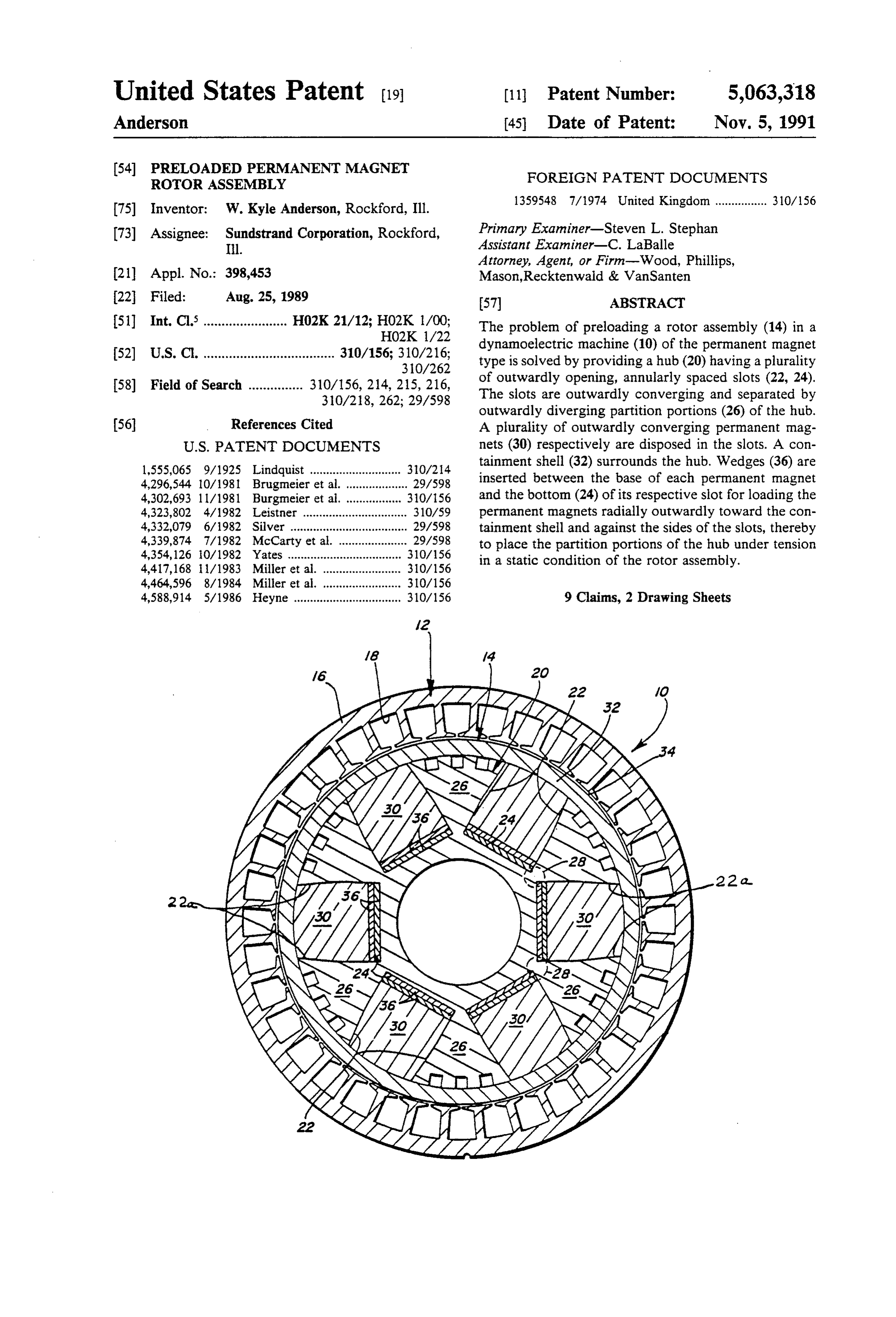
Attorney, Agent, or Firm-Wood, Phillips, 21 Appl. No.: 398,453 Mason, Recktenwald & VanSanten 22 Filed: Aug. 25, 1989 57 ABSTRACT 51) Int. Cl........................ H02K 21/12; HO2K 1/00; The problem of preloading a rotor assembly (14) in a HO2K 1/22 dynamoelectric machine (10) of the permanent magnet 52 U.S. C. .................................... 310/156; 310/216; type is solved by providing a hub (20) having a plurality
58) Field of Search ............... 310/156, 214, 215, 216, of outwardly opening, annularly spaced slots (22, 24). 310/218, 262; 29/598 The slots are outwardly converging and separated by outwardly diverging partition portions (26) of the hub.
56 References Cited A plurality of outwardly converging permanent mag
l,555,065 9/1925 Lindquist ............................ 30/214 tainment shell (32) surrounds the hub. Wedges (36) are 4,296,544 10/1981 Brugmeier et al. ... ... 29/598 inserted between the base of each permanent magnet 4,302,693 11/1981 Burgmeier et al. ... ... 310/56 and the bottom (24) of its respective slot for loading the 4,323,802 4/1982 Leistner .... ... 310/59 permanent magnets radially outwardly toward the con 4,332,079 6/1982 Silver ........ ... 29/598 tainment shell and against the sides of the slots, thereby 4,339,874 7/1982 McCarty et al. . ... 29/598 to place the partition portions of the hub under tension 4,354,126 iO/1982 Yates ................................... 310/156 in a static condition of the rotor assembly. 4,417,168 /1983 Miller et al. ........................ 3O/156 4,464,596 8/1984 Miller et al. ........................ 310/156 4,588,914 5/1986 Heyne ................................. 310/156 9 Claims, 2 Drawing Sheets
ZBN
Page 2
Drawing sheet — no readable text.
Page 3
Drawing sheet — no readable text.
Page 4
In the exemplary embodiment of the invention, the
PRELOADED PERMANENT MAGNET ROTOR rotor assembly includes a hub having a plurality of ASSEMBLY outwardly converging, annularly spaced slots separated by outwardly diverging partition portions of the hub. A
FIELD OF THE INVENTION plurality of outwardly converging permanent magnets This invention generally relates to dynamoelectric are disposed respectively in the slots. A containment machines of the permanent magnet type and, particu shell surrounds the hub. Wedge means are provided between the base of each permanent magnet and the larly, to a rotor assembly for such machines in which bottom of its respective slot for loading the permanent the permanent magnets are preloaded. 10 magnets outwardly toward the containment shell and BACKGROUND OF THE INVENTION against the sides of the slots, thereby to place the parti A dynamoelectric machine of the permanent magnet tion tion portions of the hub under tension in a static condi of the rotor assembly.
type, such as a permanent magnet generator, generally includes a rotor assembly rotatably mounted within a 5 its separating of
Regardless the configuration of the hub slots and stationary outer stator. The rotor assembly includes a means between the baseportions, partition of each by placing the wedge permanent magnet and plurality of annularly spaced permanent magnets. Usu the bottom of its respective slot, only radially out ally, the magnets are equally spaced and of an even wardly preload forces are effected toward the contain number to provide alternating polarity magnetic means ment shell.
around the periphery of the rotor assembly. The stator The wedge means are shown herein in the form of at usually includes windings arranged to magnetically least one wedge-shaped member positionable at the base couple with the rotor poles. During rotation of the of each permanent magnet in a direction axially of the rotor assembly, the flux of the permanent magnets in rotor assembly. Preferably, at least a pair of such duce an electromotive force in the stator coils. wedge-shaped members are positionable in juxtaposi When the permanent magnets are disposed around 25 tion in oppositely oriented directions axially of the rotor the radial periphery of the stator assembly, it is common assembly.
to locate the permanent magnets in radially outwardly The invention contemplates a feature wherein the opening slots annularly spaced about a rotor hub. A wedge-shaped members may have a length greater than containment shell surrounds the hub and the spaced the axial dimension of the hub. Therefore, exposed ends permanent magnets. There is a continuing problem in 30 the wedge members can be severed once a desired designing such rotor assemblies, particularly in the de of biasing load has been applied to the permanent magnets. sign of the containment shell and involving the force parameters interacting between the components, in tionOther objects, features and advantages of the inven will be apparent from the following detailed de cluding considerations of varying forces on the magnets scription taken in connection with the accompanying and the hub portions between a static condition and 35 drawings.
high speed rotational conditions during operation of the dynamoelectric machine. BRIEF DESCRIPTION OF THE DRAWINGS For instance, the hub of the rotor assembly may have The features of this invention which are believed to outwardly diverging partition portions separating the be novel are set forth with particularity in the appended permanent magnets, with the magnets being disposed in claims. The invention, together with its objects and the outwardly converging slots. It has been discovered that advantages thereof, may be best understood by refer the typical design approach results in the root area ence to the following description taken in conjunction between the hub slots being subjected to compressive with the accompanying drawings, in which like refer forces, even during operation of the machine at high ence numerals identify like elements in the figures and rotational speeds. This results in inefficient design pa 45 in which:
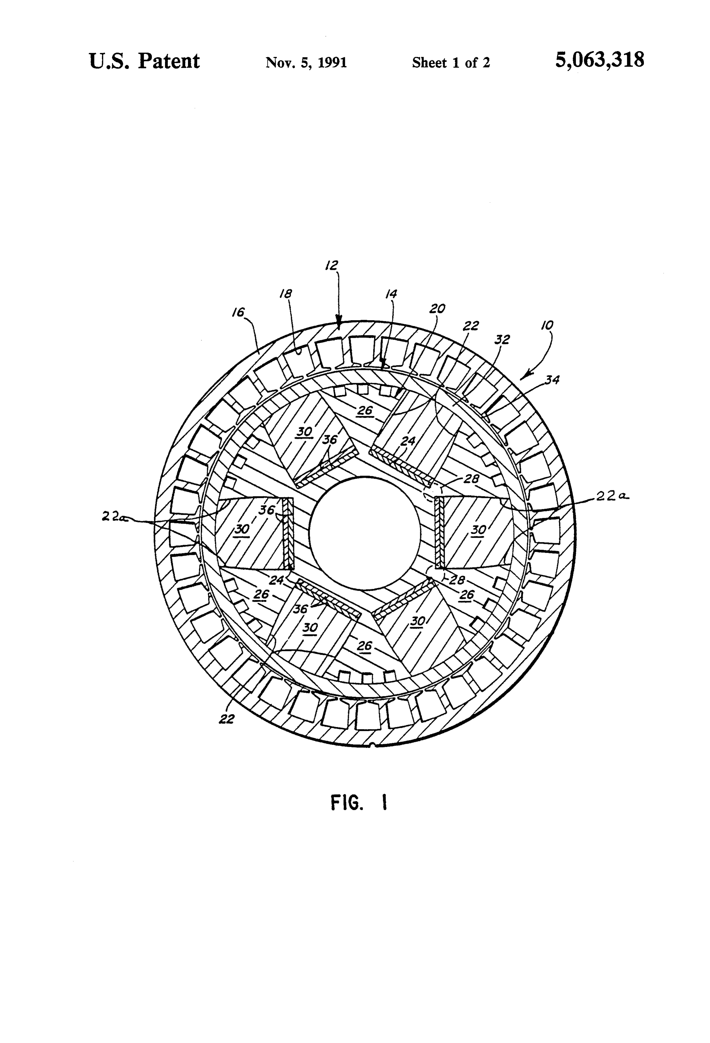
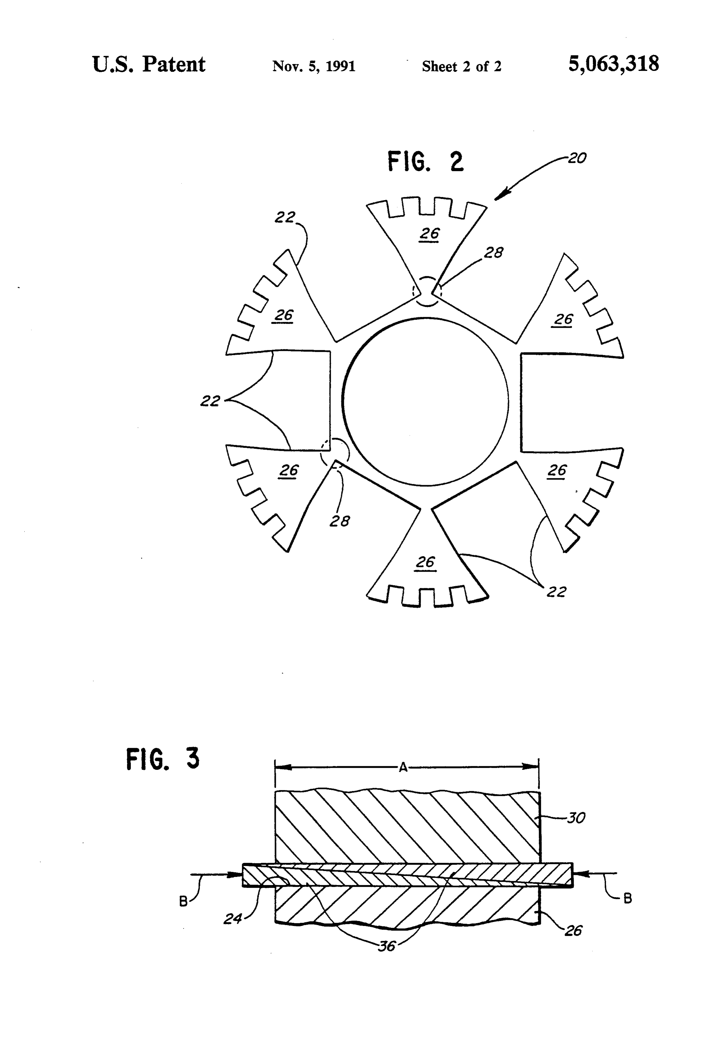
rameters, particularly in the outer containment shell FIG. 1 is a radial section through a dynamoelectric which often is overdesigned in its strength parameters machine incorporating a preloaded rotor assembly em or simply is made too thick. In aerospace applications, bodying the concepts of the invention; this results in excessive size and weight parameters FIG. 2 is a radial section through the hub component which are critical in aerospace applications. With such 50 of the rotor assembly; and outwardly diverging hub portions between the out FIG. 3 is a section through a pair of oppositely di wardly converging spaced slots, it would be ideal to rected, juxtaposed wedge members used to preload the somehow place the root areas of the hub portions under permanent magnets.
tension. Regardless of the slot configuration, it would DETAILED DESCRIPTION OF THE be desirable to preload the permanent magnets in such a 55 PREFERRED EMBODIMENT manner that the load is directed only in a radially out ward direction toward the containment shell. Referring to the drawings in greater detail, and first This invention is directed to solving the above prob to FIG. 1, the basic components of a dynamoelectric lems and satisfying the stated needs by providing a machine, generally designated 10, of the permanent preloading system which enables the containment shell magnet type, are generally shown. Specifically, such a to be designed with lower strength requirements and/or permanent magnet machine includes a stationary outer thinner dimensions than has been heretofore affordable. stator assembly, generally designated 12, and an inner
SUMMARY OF THE INVENTION
rotatable rotor assembly, generally designated 14.
Stator assembly 12 is generally conventional and
An object, therefore, of the invention is to provide a 65 includes a cylindrical housing 16 having a plurality of new and improved preloaded rotor assembly for use in axially extending, radially spaced slots 18 within which a dynamoelectric machine of the permanent magnet a number of windings (not shown) are arranged to mag type. netically couple with the poles of rotor assembly 14.
Page 5
During rotation of rotor assembly 14, a varying flux wedges 36 is to apply a radial tension force on hub linkage is created between the permanent magnets (de partition portions 26 at root areas 28. scribed below) and the stator coils, inducing an electro As the rotor speed is increased during operation, centrifugal force will act upon permanent magnets 30 motive force in each of the coils. Of course, this general operation of such a dynamoelectric machine, such as a 5 and reduce the radially outward force against the mag permanent magnet generator, is well known. nets provided by wedges 36. As the centrifugal force Rotor assembly 14 includes a hub, generally desig reduces the radially outward force provided by the nated 20 (also see FIG. 2), having a plurality of out wedges, because of the decrease in the force now ex wardly converging, annularly spaced slots defined by erted by the wedges, the net radially outward force converging side walls 22 and bottom walls 24. The slots 10 against the containment shell will remain generally are separated by outwardly diverging partition portions constant from a rest condition to a rotating condition. 26 of the hub. It can be seen that each partition portion Shell loads can be preloaded to maximum stress, and 26 terminates radially inwardly at a root area as indi therefore shell stress cycling can be eliminated. In es cated by circles 28. sence, the preloading forces provided by the wedges A permanent magnet 30 is disposed in each slot of 15 which apply tensile forces at root areas 28, permit the hub 20. It can be seen that the permanent magnets are use of a thinner containment shell 32 or, alternatively, a shaped complementarily to the slots, i.e. each perma sleeve made from a material having a lesser strength. nent magnet converges radially outwardly in a nating Obviously, this permits a more efficient rotor design. A relationship with the converging side walls 22 of the designer can tailor the stress distribution of the hub and slots. 20 the shell in order to take maximum advantage of their A cylindrical containment shell 32 surrounds hub 20, material properties.
contains permanent magnets 30 and defines an air gap In fact, the wedges can be designed to actually cancel 34 between rotor assembly 14 and stator assembly 12. out the forces involved. In other words, once the cen Generally, the invention contemplates means for preloading rotor assembly 14 by radially outwardly 25 trifugal magnets forces caused by the masses of the permanent are calculated, the loading forces of the loading permanent magnets 30 to apply a radially out wedges can be matched therewith. For instance, if the ward bias against partition portions 26 of hub 20, with centrifugal force is calculated to build up to "X" psi, by the bias preferably being only in a direction radially outwardly toward containment shell 32. More particu applying a radially outward loading force on the mag larly, wedges 36 are forced in a direction axially of the 30 nets of "X" psi, through wedges 36 as stated above the rotor assembly between the base of each permanent centrifugal force on the wedges reduces the force pro magnet 30 and bottom wall 24 of its respective slot in vided by the wedges. Therefore, the centrifugal force would cancel out the force applied by the wedges at hub 20. These wedges bias the permanent magnets radi ally outwardly toward containment shell 32 and are maximum speed and, in essence, there would be a force effective to place partition portions 26 of hub 20 under 35 direction shift with very minor movement of the con tension, such as at root areas 28. ponents and, consequently, under some circumstances As stated above, it has been discovered that the root the containment shell could be eliminated. areas 28 of partition portions 26 of hub 20, between the To this end, FIG.3 shows a concept wherein a pair of hub slots, are subjected to compressive forces by the wedges 36 are positioned between the base of each containment shell, even during operation at high rota- 40 permanent magnet 30 and botton wall 24 of its respec tional speeds. This is what occurs with heretofore avail tive slot. The wedges are in oppositely oriented direc able rotor assemblies of the character described herein. tions axially of the rotor assembly. Arrow "A' indicates These compressive loads are reduced somewhat at the axial dimension of rotor hub 26 and magnet 30. The speed, but the shell loads increase with speed, resulting wedges can be forced in opposite directions, in the in shell stress cycles. At high speeds, centrifugal force 45 direction of arrows "B", until a desired radially out tends to expand the containment shell, which is another ward loading force is achieved. At this point, the pro design consideration to be met. Ideally, at maximum truding ends of the wedges can be severed. In other speed, all fibers in the hub and the containment shell words, the wedges initially can be designed longer than should be helping to retain the permanent magnets. the width of the rotor hub to provide for easily varying In order to compensate for all of these various condi- 50 the biasing force.
tions, it has been conventional to take the easiest route It will be understood that the invention may be em and simply overdesign the containment shell either in its bodied in other specific forms without departing from strength parameters or its size, i.e. thickness. The prob the spirit or central characteristics thereof. The present len with this simple approach is that the weight and size examples and embodiments, therefore, are to be consid of the machine is unnecessarily increased which, in 55 ered in all respects as illustrative and not restrictive, and aerospace applications, is quite undesirable. The inven the invention is not to be inited to the details given tion recognizes a solution in which partition portions 26 herein.
of hub 20, particularly in the root areas 28 thereof, are I claim:
placed under tension by preloading permanent magnets 1. In a dynamoelectric machine of the permanent 30 in a radially outward direction. The immediate ad- 60 magnet type, a rotor assembly comprising: vantage to such a system is to allow the use of a contain a hub having a plurality of outwardly converging ment shell that either is thinner in cross-section or lower annularly spaced slots separated by outwardly di in strength requirements than could be heretofore per verging partition portions of the hub, mitted. In essence, wedges 36 exert a radially outward at least one said slot being defined by an outwardly load on permanent magnets 30 which, in turn, apply a 65 facing bottom and circumferentially spaced side radially outward load against inward tapered portions walls, said sidewalls converging in a radially out 22a of side walls 22 of the slots defined by the converg ward direction only from a point spaced radially ing partition portions 26. The result of the action of outwardly from the bottom;
Page 6
a plurality of outwardly converging permanent mag there is a solid mass between the bottom of the one nets respectively disposed in the slots; slot and the magnet in the one slot. a containment shell surrounding the hub; and 5. In a dynamoelectric machine as set forth in claim 4, wedge means between a base of each permanent mag wherein said means for loading comprise at least one net and a bottom of its respective slot for loading wedge-shaped member having spaced-apart ends with the permanent magnets radially outwardly toward different thicknesses, whereby said wedge member is the containment shell and against sides of the slots forcibly positioned in a direction axially of the rotor to place the partition portions of the hub under assembly to bias the permanent magnets radially out tension at least in a static condition of the rotor wardly toward the containment shell. assembly, O 6. In a dynamoelectric machine as set forth in claim 4, said wedge means comprising first and second wherein said means for loading comprise at least one wedge-shaped members having spaced-apart ends wedge-shaped member having spaced-apart ends with with different thicknesses, each of said wedge different thicknesses, each of said pair of wedge-shaped shaped members arranged in opposite juxtaposed 15 whereby members arranged in opposite juxtaposed relation, relationship with the wedge members forcibly posi bers are forcibly said pair of oppositely oriented wedge men tioned in a direction axially of the rotor to bias one rotor assembly topositioned in a direction axially of the bias the permanent magnets radially of the magnets radially outwardly toward the con outwardly toward the containment shell. tainment shell.
7. In a dynamoelectric machine of the permanent 2. In a dynamoelectric machine as set forth in claim 1, 20 magnet wherein said wedge-shaped members are each Solid to type, a rotor assembly comprising: define a solid mass between the bottom of the slot and a hub having a plurality of annularly spaced, radially the one magnet. outwardly opening slots, at least one said slot 3. In a dynamoelectric machine as set forth in claim 1, bounded by a bottom and circumferentially spaced wherein said wedge means comprise at least a pair of 25 sidewalls, said sidewalls converging over only a wedge-shaped members having spaced-apart ends with portion of the radial extent thereof; different thicknesses, each of said pair of wedge-shaped a plurality of permanent magnets respectively dis members arranged in opposite juxtaposed relation, posed in the slots;
whereby said pair of oppositely oriented wedge men a containment shell surrounding the hub; and bers are forcibly positioned in a direction axially of the 30 wedge net means between a base of each permanent mag and a bottom of its respective slot for loading rotor assembly to bias the permanent magnets radially the permanent magnets only in a direction radially outwardly toward the containment shell. outwardly toward the containment shell, said 4. In a dynamoelectric machine of the permanent wedge means comprising at least one wedge magnet type, a rotor assembly comprising: shaped member with oppositely facing surfaces for a hub having a plurality of outwardly converging 35 engaging the bottom and a magnet in the one slot, annularly spaced slots separated by outwardly di the wedge-shaped member being solid between its verging partition portions integral with the hub, oppositely facing surfaces to allow a positive out each partition portion having an associated root ward force to be exerted on the magnet in the one portion, each slot having an outwardly facing bot slot by forcibly directing the wedge-shaped men tom; ber between the bottom of the one slot and the a plurality of outwardly converging permanent mag magnet in the one slot.
nets respectively disposed in the slots; 8. In a dynamoelectric machine as set forth in claim 7, a containment shell surrounding the hub and adapted wherein said wedge means comprise at least one wedge to subject the root portions to compressive force; shaped member having spaced-apart ends with different and 45 thicknesses, whereby said wedge member is forcibly means for loading the permanent magnets only in a positioned in a direction axially of the rotor assembly to direction radially outwardly toward the contain bias the permanent magnets radially outwardly toward ment shell and against sides of the slots to place the the containment shell.
partition portions of the hub under tension at least 9. In a dynamoelectric machine as set forth in claim 7, in a static condition of the rotor assembly, said 50 wherein said wedge means comprise at least a pair of loading means comprising first and second wedge wedge-shaped members having spaced-apart ends with shaped members having spaced-apart ends with different thicknesses, each of said pair of wedge-shaped different thicknesses, each of said wedges arranged members arranged in opposite juxtaposed relation, in opposite juxtaposed relationship with the whereby said pair of oppositely oriented wedge mem wedges being forcibly positioned in one of the slots 55 bers are forcibly positioned in a direction axially of the in a direction axially of the rotor between the bot rotor assembly to bias the permanent magnets radially tom of one of the slots and a magnet in the one slot, outwardly toward the containmentsk shell. said wedge-shaped members being solid so that
Provenance
- Collection
- Cited prior art
- Original PDF
- patentimages.storage.googleapis.com →
- Filed
- 1989-08-25
- Pages
- 6
- Method
- pdftotext (the PDF's own text layer) + pdftoppm 300dpi page scans
- Source
- Google Patents bibliographic record
- Granted
- 1991-11-05
- Inventors
- W. Kyle Anderson; Sundstrand Corp
- Transcribed from
- patentimages.storage.googleapis.com →