patent · US5986378
Electric motor and generator having amorphous core pieces being individually accommodated in a dielectric housing
16 November 1999
Page 1 — bibliographic record
United States Patent (19) 11 Patent Number: 5,986,378 Caamaño (45) Date of Patent: Nov. 16, 1999 54 ELECTRIC MOTOR AND GENERATOR 5,179,307 1/1993 Porter .................................... 310/68 B HAVING AMORPHOUS CORE PIECES 5,208,503 5/1993 Hisey ---- ------------- --- --- ------- --- --- -- 310/259
BEING INDIVIDUALLY ACCOMMODATED 5. SE Bibe 2- - -2 C . . . . . . . . . . . .. ... ... ... ... ... .. . . . . . . . . . . . . .
INA DELECTRIC HOUSING 5,363,002 11/1994 Hernden et al. .......................... 31.0/54 aw 5,428,276 6/1995 Carobolante et al. .. 318/254 75 Inventor: Ramon A. Caamafio, Gilroy, Calif. 5,554.232 9/1996 Fujimoto et al. ....................... 148/304 73 Assignee: Light Engineering Corporation, 5,633,545 5/1997 f Albrecht eC ete al.
Gilory, Calif. OTHER PUBLICATIONS * Notice: This patent is Subject to a terminal dis- W. R. Mischler, “Test Results on a Low LOSS Amorphous claimer. Iron Induction Motor”, Jun. 1981, IEEE Transactions on Power Apparatus and Systems, vol. PAS-100, No. 6.
G. B. Kliman, “Permanent Magnet AC Disc Motor Electric 21 Appl. No.: 09/185,297 Vehicle Drive”, Mar. 1983, SEA Technical Paper Series, 22 Filed: Nov. 3, 1998 Soc. Of Automotive Eng., Paper No. 830111.
Related U.S. Application Dat Primary y Examiner Thomas M. Doughert gnerly eae pplication Uata Assistant Examiner Tran N Nguyen 63 Continuation of application No. 09/111.249, Jul. 3, 1998, Attorney, Agent, or Firm Jay R. Beyer; Stephen C. Shear which is a continuation of application No. 08/963,290, Nov.
3, 1997, Pat. No. 5,814,914, which is a continuation of 57 ABSTRACT
649. A device Such as an electric motor, an electric generator, or 6 a regenerative electric motor includes a rotor arrangement 51 Int. C. ------- --- --- ------------- - HO2K 21/12; HO2K 37/12 and a StatOr arrangement. The StatOr arrangement has
52 U.S. Cl. .............................. 310/216; 310/43; 310/45; dielectric electromagnet housing and at least one energizable 310/89; 310/179 electromagnet assembly including an overall amorphous 58 Field of Search ................................ 310/43, 45, 113, metal magnetic core. The Overall amorphous metal magnetic 310/179, 216, 218, 254, 258, 259, 264, core is made up of a plurality of individually formed 268; 29/596,598, 609 amorphous metal core pieces. The dielectric electromagnet
O housing has core piece openings formed into the electro 56) References Cited magnet housing for holding the individually formed amor
So as to form the Overall amorphous metal magnetic core.
3,840,764 10/1974 Burger .................................... 310/185 The device further includes a control arrangement that is 4,187,441 2/1980 Oney. ... 310/112 able to variably control the activation and deactivation of the
ises
electromagnet using any combination of a plurality of acti 4,547,713 10/1985 Langley et al. ... ... 310/254 E. R style part inst, to control the 4,578,610 3/1986 Kliman et al. ... loss speed, eliciency, torque, and power of the device. 4,705,578 11/1987 Lin et al. .......... ... 148/108 4,866,321 9/1989 Blanchard et al. ..................... 310/112 26 Claims, 7 Drawing Sheets
40 28c.
36e 36c J-Y 32
S 4. 3239
Ned
S 36d -
Page 2
Drawing sheet — no readable text.
Page 3
Drawing sheet — no readable text.
Page 4
Drawing sheet — no readable text.
Page 5
Drawing sheet — no readable text.
Page 6
Drawing sheet — no readable text.
Page 7
Drawing sheet — no readable text.
Page 8
Drawing sheet — no readable text.
Page 9
ELECTRIC MOTOR AND GENERATOR is reduced when it is Subjected to physical Stresses. This HAVING AMORPHOUS CORE PIECES reduced permeability may be considerable depending upon BEING INDIVIDUALLY ACCOMMODATED the intensity of the Stresses on the amorphous metal material. INA DELECTRIC HOUSING AS an amorphous metal magnetic core is Subjected to Stresses, the efficiency at which the core directs or focuses
This is a Continuation application of copending prior magnetic flux is reduced resulting in higher magnetic losses, application Ser. No. 09/111.249 filed on Jul. 3, 1998, which reduced efficiency, increased heat production, and reduced is a continuation of application Ser. No. 08/963,290 filed on power. This phenomenon is referred to as magnetostriction Nov. 3, 1997 that issued as U.S. Pat. No. 5,814,914 on Sep. and may be caused by Stresses resulting from magnetic 29, 1998, which is a continuation of application Ser. No. forces during the operation of the motor or generator, 08/774,946 filed on Dec. 27, 1996 and now issued as U.S. mechanical Stresses resulting from mechanical clamping or Pat. No. 5,731,649 on Mar. 24, 1998. otherwise fixing the magnetic core in place, or internal Stresses caused by the thermal expansion and/or expansion
BACKGROUND OF THE INVENTION due to magnetic Saturation of the amorphous metal material. The present invention relates generally to electric motors, 15 Conventional magnetic cores are formed by laminating generators, and regenerative motors. The term regenerative Successive layers of core material together to form the motor is used herein to refer to a device that may be operated overall core. However, as mentioned above, amorphous as either an electric motor or a generator. More specifically, metal is difficult to cut or form easily. Therefore, in the past, the invention relates to an electric motor, generator, or amorphous metal cores have often been formed by rolling an regenerative motor including a Stator arrangement which amorphous metal ribbon into a coil with each Successive itself includes an electromagnet assembly having an amor layer of the material being laminated to the previous layer phous metal magnetic core made up of a plurality of using an adhesive Such as an epoxy. When in use in an individually formed amorphous metal core pieces. The electric motor or generator, this laminated construction present invention also provides a control arrangement that is 25 restricts the thermal and magnetic Saturation expansion of able to variably control the activation and deactivation of an the coil of amorphous metal material and results in high electromagnet using any combination of a plurality of acti internal Stresses. These Stresses cause magnetostriction that Vation and deactivation parameters in order to control the reduces the efficiency of the motor or generator as described Speed, efficiency, power, and torque of the device. above. Also, this construction places a layer of adhesive The electric motor and generator industry is continuously material iseach between coil of the core. Since amorphous metal
Searching for ways to provide motors and generators with example only a coupleprovided typically of mils as a very thin ribbon, for thick, a significant percentage increased efficiency and power density. For Some time now, of the Volume of the core ends up being adhesive material. it has been believed that motors and generators constructed This volume of adhesive reduces the overall density of the using permanent Super magnet rotors (for example cobalt amorphous metal material within the laminated rare earth magnets and Neodymium-Iron-Boron magnets) 35 therefore, undesirably reduces the efficiency of thecore, and core to and Stators including electromagnets with amorphous metal focus or direct the magnetic flux for a given volume of magnetic cores have the potential to provide Substantially overall core material.
higher efficiencies and power densities compared to con ventional motors and generators. Also, because amorphous for minimizinginvention
The present the provides a method and arrangement
Stresses on an amorphous metal magnetic metal cores are able to respond to changes in a magnetic 40 core in an electric motor, generator, or regenerative motor. field much more quickly than conventional ferrous core This method and arrangement eliminates the need for lami materials, amorphous metal magnetic cores have the poten nating the various layers of the amorphous metal thereby tial to allow much faster field Switching within motors and reducing the internal Stresses on the material and increasing generators, and therefore allow much higher Speed and the density of the amorphous material within the better controlled motors and generators than conventional 45 core. Also, in order to take advantage of the highoverall ferrous cores. However, to date it has proved very difficult Switching capabilities of the amorphous metal magneticSpeed to provide an easily manufacturable motor or generator material, the present invention provides control methodscore and which includes amorphous metal magnetic cores. arrangements that are able to variably control the activation Amorphous metal is typically Supplied in a thin continu and deactivation of the electromagnet of an electric motor, ous ribbon having a uniform ribbon width. However, amor 50 generator, or regenerative motor device including an amor phous metal is a very hard material making it very difficult phous metal magnetic core by using a combination of a to cut or form easily, and once annealed to achieve peak plurality of different activation and deactivation parameters magnetic properties, becomes very brittle. This makes it in order to control the Speed, efficiency, torque, and power difficult and expensive to use the conventional approach to of the device.
constructing a magnetic core. This conventional approach 55 typically involves cutting individual core layerS having a SUMMARY OF THE INVENTION desired shape from a sheet of core material and laminating AS will be described in more detail hereinafter, a device the layers together to form a desired overall magnetic core Such as an electric motor, an electric generator, or a regen shape. The brittleness of amorphous metal also causes erative electric motor is disclosed herein. The device concern for the durability of a motor or generator which 60 includes a rotor arrangement, at least one Stator utilizes amorphous metal magnetic cores. Magnetic cores arrangement, and a device housing for Supporting the rotor are Subject to extremely high magnetic forces which change arrangement and the Stator arrangement in the predeter at very high frequencies. These magnetic forces are capable mined positions relative to one another. The device housing of placing considerable stresses on the core material which also Supports the rotor arrangement for rotation along a may damage an amorphous metal magnetic core. 65 predetermined rotational path about a given rotor axis. The Another problem with amorphous metal magnetic cores is Stator arrangement has at least one energizable electromag that the magnetic permeability of amorphous metal material net assembly including an overall amorphous metal mag
Page 10
netic core and an electric coil array which together define at given rotor axis. The electromagnet of the Stator arrange least one magnetic pole piece. The overall amorphous metal ment includes a generally C-shaped overall amorphous magnetic core is made up of a plurality of individually metal magnetic core having two pole pieces with each of the formed amorphous metal core pieces. The Stator arrange pole pieces positioned adjacent to a corresponding one of the ment also includes a dielectric electromagnet housing for 5 predetermined rotational paths of the north and South poles Supporting the electromagnet assembly Such that the mag of the rotor magnet. The Overall magnetic core of the netic pole pieces are positioned adjacent the rotational path electromagnet assembly is a generally C-shaped overall of the rotor arrangement. The dielectric electromagnet hous amorphous metal magnetic core defining the two pole pieces ing has core piece openings formed into the electromagnet Such that each of the pole pieces is positioned adjacent to a housing for holding the individually formed amorphous corresponding one of the different predetermined rotational metal core pieces in positions adjacent to one another So as paths. The two pole pieces are each individually formed to form the overall amorphous metal magnetic core. amorphous metal core pieces. Additional individually formed
In one preferred embodiment, the rotor arrangement has netic yoke amorphous metal core pieces form an electromag at least one rotor magnet with north and South poles and the another Such magnetically coupling the two pole pieces to one rotor arrangement has an arrangement for Supporting the C-shaped overall 15 that the core pieces together define the rotor magnet for rotation about a given rotor axis Such that core.
at least one of the magnet's poles is accessible along a A method of making an amorphous metal magnetic core predetermined rotational path about the given rotor axis. In for an electromagnet of a device Such as an electric motor, an electric generator, or a regenerative electric motor is also a preferred embodiment, the rotor magnet is a Super magnet.
In some embodiments, the individually formed amor plurality herein.
disclosed
The method includes the Step of forming a individually formed amorphous metal core phous metal core pieces are amorphous metal windings pieces, each having a desired core piece shape. A dielectric formed from a continuous ribbon of amorphous metal. magnetic core housing including magnetic core piece open Preferably, the continuous ribbon of amorphous metal has a substantially constant ribbon width. The individually formed 25 ings that define the desired overall magnetic core shape is provided. The plurality of individually formed amorphous amorphous metal core pieces may have a variety of croSS
Sectional shapes including a circle, an Oval, an egg shape, a metal of the core pieces are assembled into the core piece openings dielectric magnetic core housing Such that the dielec toroidal ring, a triangle having rounded corners, and a tric core trapezoid having rounded corners. Alternatively, the indi another Sohousing as to holds the core pieces adjacent to one form the desired overall magnetic core vidually formed amorphous metal core pieces may be shape. In a preferred method, each core piece is wound into formed from individual Strips of amorphous metal material its final shape from a continuous ribbon of amorphous metal. Stacked in an associated core piece opening of a core piece In accordance with another aspect of the present housing. Also, in Some embodiments, any voids in the core piece openings of the electromagnet housing holding the invention,rotational a method and arrangement for controlling the
Speed and input/output power and torque of a amorphous metal core pieces are filled with a dielectric oil.
Additionally, the amorphous metal core pieces may be oil 35 device Such as an electric motor, an electric generator, or a regenerative electric motor is disclosed herein. The device impregnated. includes a rotor Supported for rotation along a predetermined In one embodiment, the Stator arrangement includes a rotor path about a given rotor axis. Preferably, the rotor plurality of electromagnet assemblies, each having a plural includes at least one permanent Super magnet. The device ity of pole pieces. Each of the pole pieces is an individually 40 also includes a Stator having a plurality of dynamically formed amorphous metal core piece. Furthermore, at least activatable and deactivatable electromagnet assemblies (also one of the individually formed amorphous metal core pieces referred to herein merely as electromagnets) with amor is a toroidal ring forming an electromagnetic yoke magneti phous metal magnetic cores. The electromagnets are spaced cally coupling each of the pole pieces to one another. The apart from one another adjacent to the predetermined rotor toroidal ring electromagnetic yoke includes an annular or 45 path Such that movement of a particular point on the rotor other Such continuous Surface defined by one continuous (rotor point) from a given point adjacent one electromagnet edge of the continuous ribbon of amorphous metal after the (stator point) to a given point adjacent the next Successive ribbon of amorphous metal has been wound about itself. electromagnet (stator point) defines one duty cycle. A posi Each of the pole pieces of the electromagnet assembly has tion detector arrangement determines the position and rota a first end (defined by one continuous edge of the ribbon) 50 tional Speed of the rotor relative to the Stator at any given positioned adjacent the predetermined rotational path of the time in a duty cycle and produces corresponding Signals. A rotor magnet. Also, each of the pole pieces of the electro controller responsive to the Signals controls the activation magnet assembly has a second end (defined by the other and deactivation of the electromagnets of the Stator using continuous edge of the ribbon) positioned adjacent the predetermined device control Settings Such that, for each annular Surface of the toroidal ring electromagnetic yoke. 55 duty cycle, the controller is able to control any combination In another embodiment, the electromagnet of the Stator of a plurality of activation and deactivation parameters in arrangement includes a generally U-shaped overall amor order to control the Speed, efficiency, and input/output power phous metal magnetic core having two pole pieces. The two and torque of the device.
pole pieces are each individually formed amorphous metal In a preferred embodiment, the activation and deactiva core pieces. An additional individually formed amorphous 60 tion parameters include (i) the duty cycle activation time metal core piece forms an electromagnetic yoke magneti which is the continuous duration of time in which the cally coupling the two pole pieces to one another Such that electromagnet of the stator is activated (with either one the core pieces together define the U-shaped overall core. polarity or the other) for each duty cycle, (ii) the start/stop In Still another embodiment, the arrangement Supporting points of the duty cycle activation time which are the times the rotor magnet Supports the rotor magnet Such that both the 65 at which the duty cycle activation time Starts and stops north and South poles of the rotor magnet are accessible during the duty cycle relative to the rotational position of the along different predetermined rotational paths about the rotor as it moves through the duty cycle from Stator point to
Page 11
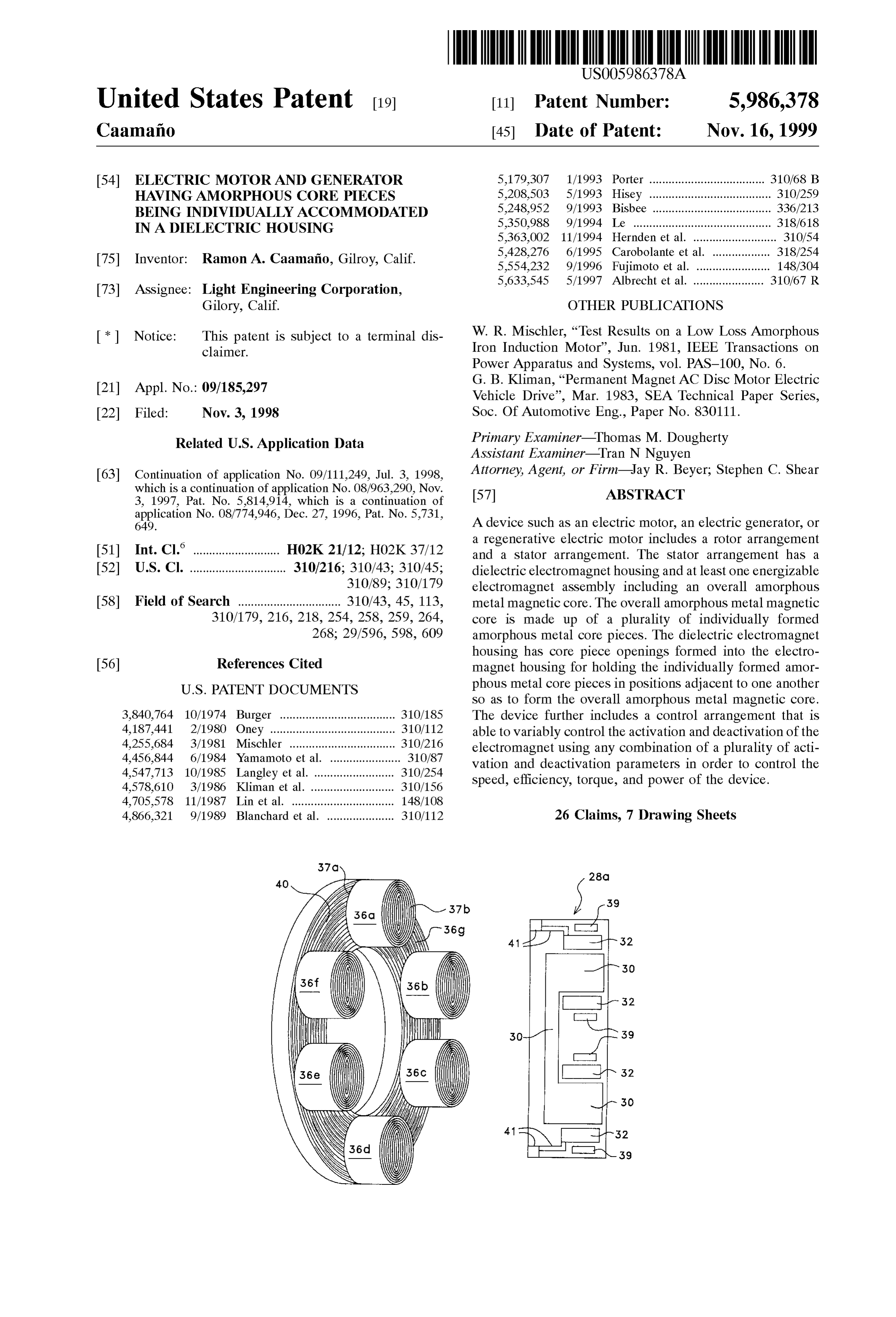
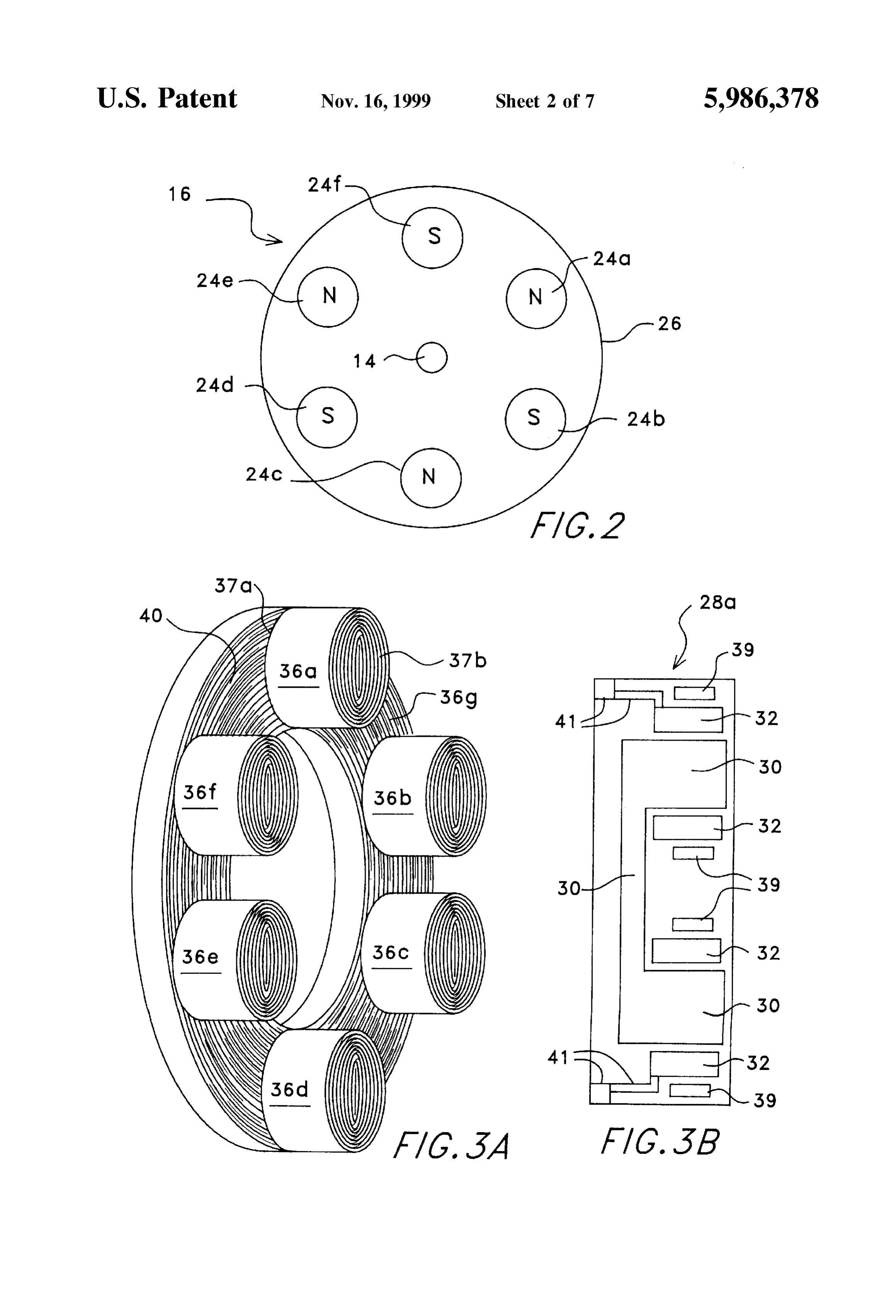
S 6 the next adjacent Stator point, and (iii) the modulation of the FIG. 3B is a diagrammatic cross-sectional view of the duty cycle activation time which is the pulse width modu stator housing of FIG. 1.
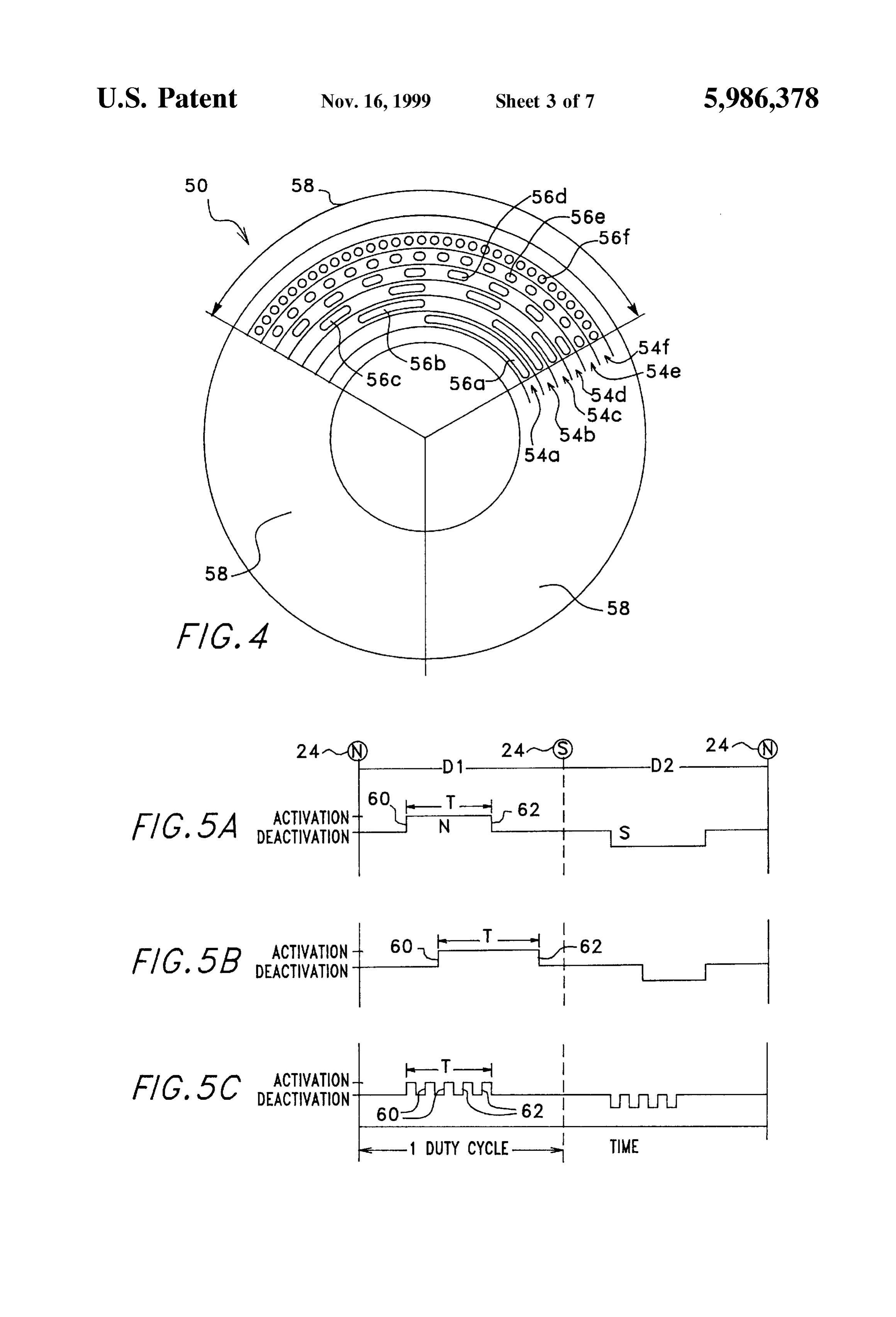
lating of the electromagnet by activating and deactivating FIG. 4 is a diagrammatic plan view of the encoder disk of the electromagnet during what would otherwise be the the device of FIG. 1.
continuous duty cycle activation time. FIG. 5 is a graph illustrating various activation and In another embodiment, the position detector arrangement deactivation parameters which the control arrangement of includes an encoder disk Supported for rotation with the the device of FIG. 1 may use to control the device of FIG. rotor and also includes an array of optical Sensors arranged 1.
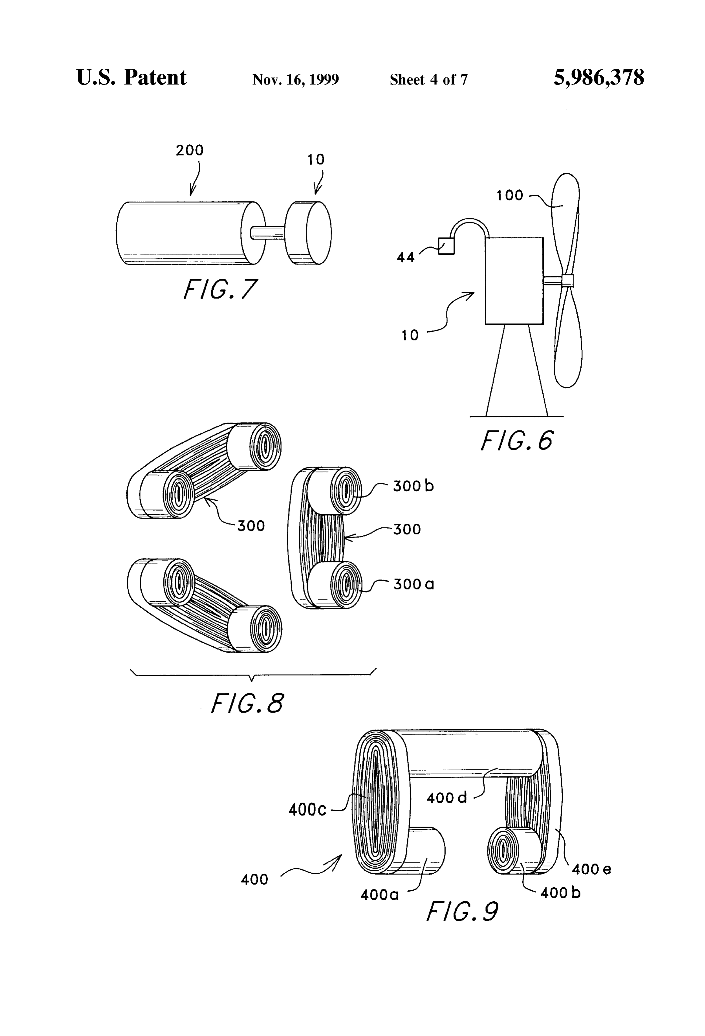
in close proximity to the encoder disk. The encoder disk has FIG. 6 is a diagrammatic view of one embodiment of the a plurality of concentric tracks with Spaced apart position invention in which a windmill drives a generator designed in indicating openings which are actually through-holes in the accordance with the invention.
disk. Each of the optical Sensors corresponds to and is FIG. 7 is a diagrammatic view of another embodiment of optically aligned with an associated one of the concentric the invention in which a turbine engine drives a generator trackS Such that each Sensor is able to detect the presence of designed in accordance with the invention. the position indicating openings defining its associated con 15 FIG. 8 is a perspective view of a second embodiment of centric track So as to be able to detect the position of the an overall amorphous metal magnetic core designed in rotor relative to the Stator. Preferably these openings are accordance with the present invention. sized and positioned to represent a digital byte of rotor FIG. 9 is a perspective view of a third embodiment of an positional information with each track contributing one bit overall amorphous metal magnetic core designed in accor of the overall digital byte. In this way, during Startup of the motor/generator device, the position of the rotor can be dance with the present invention.
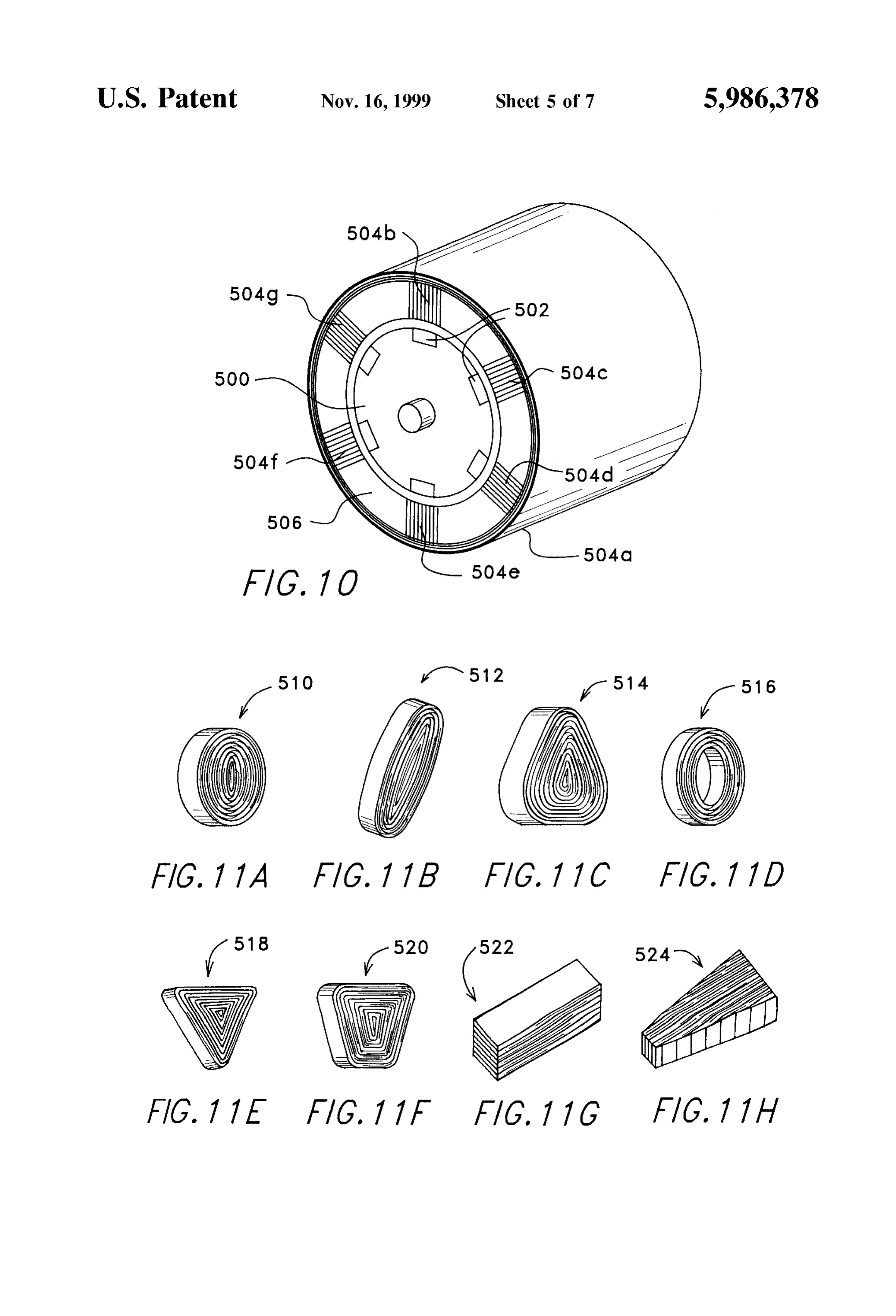
precisely determined. FIG. 10 is a perspective view of a fourth embodiment of In still another embodiment, the controller further an overall amorphous metal magnetic core designed in includes a counter arrangement capable of counting in accordance with the present invention.
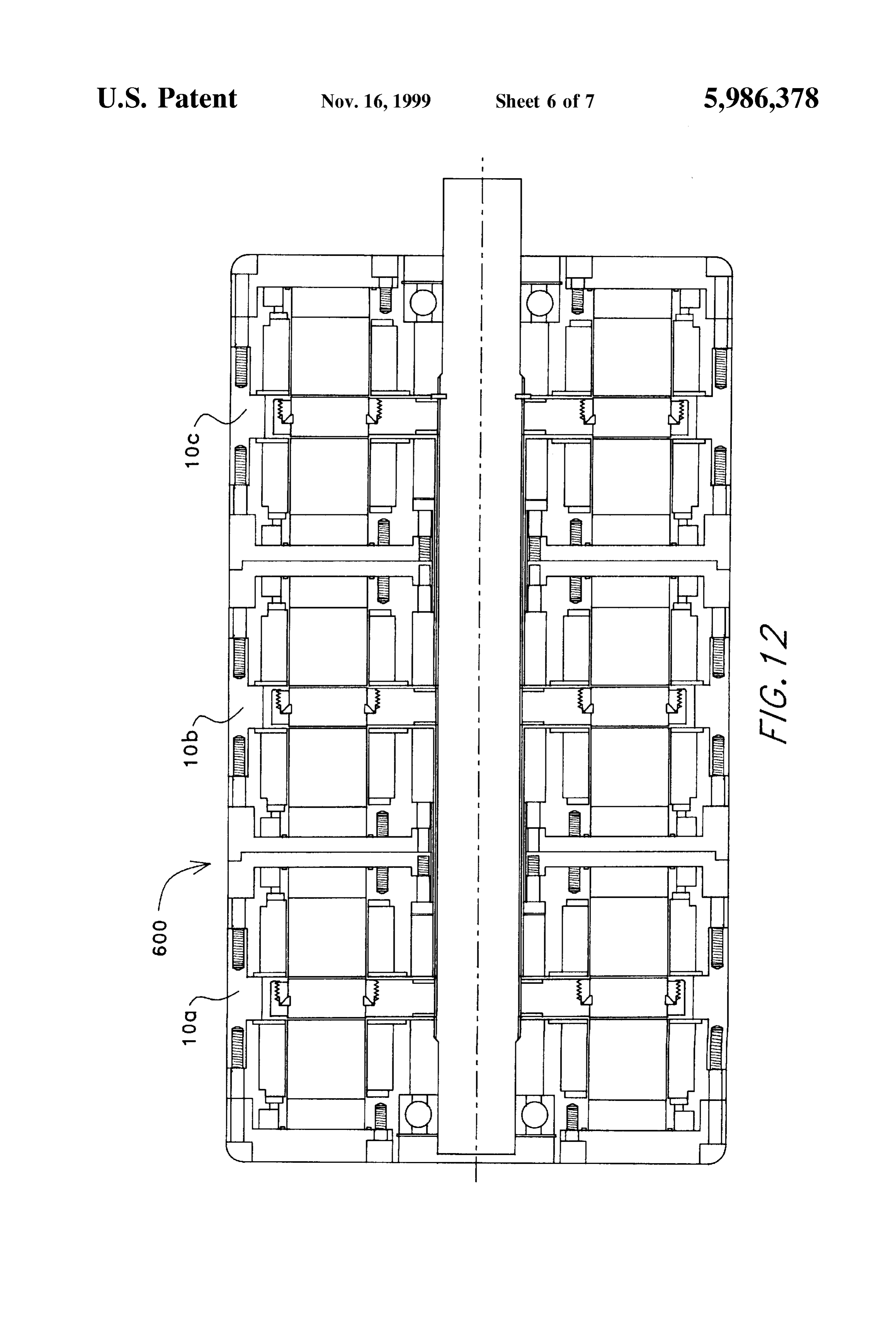
increments of time which allow each duty cycle to be FIGS. 11A-H are diagrammatic perspective views of divided into a multiplicity of time periods which the con 25 various embodiments of the individual amorphous metal troller uses to control when to activate and deactivate the core pieces having various croSS-Sectional shapes. electromagnet. FIG. 12 is a diagrammatic croSS-Sectional view of a In accordance with another aspect of the present multiphase device designed in accordance with the present invention, a method and arrangement for conditioning the invention.
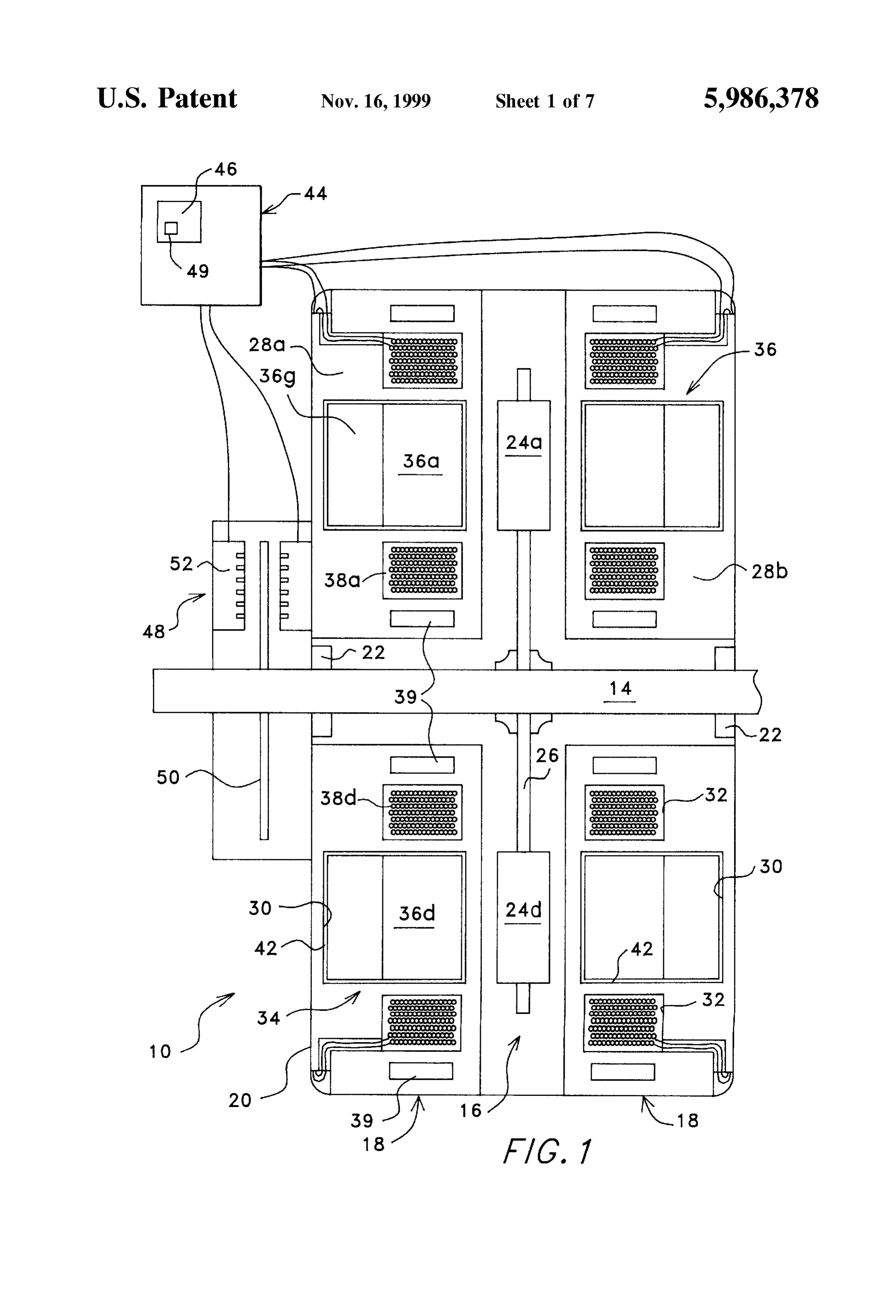
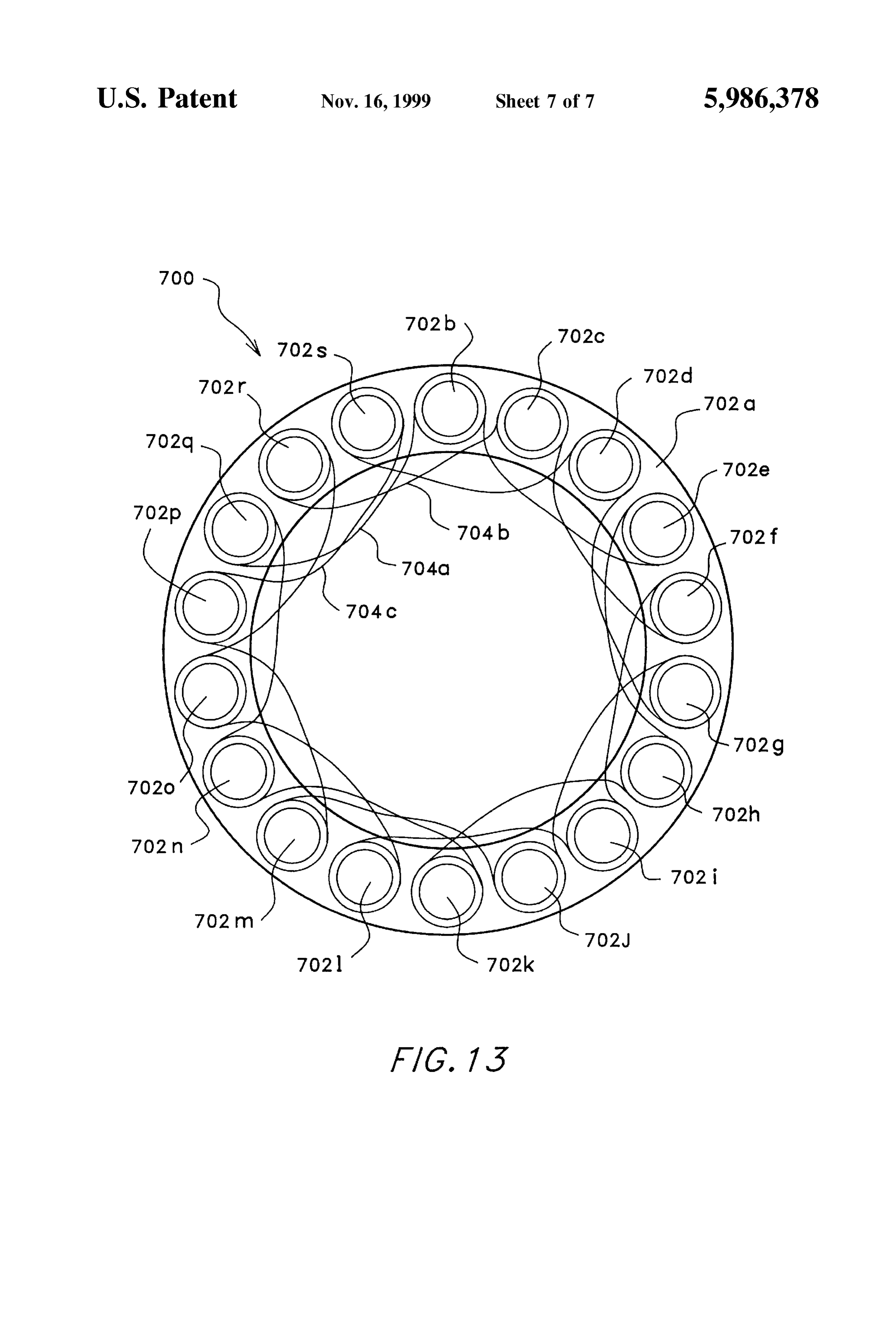
electrical output of an electric generator driven by a input FIG. 13 is a diagrammatic plan View of a Stator arrange drive device is disclosed. The generator includes a Stator ment of another embodiment of a multiphase device assembly having at least one dynamically activatable and designed in accordance with the present invention. deactivatable stator coil and a rotor assembly. A position DETAILED DESCRIPTION OF THE detector arrangement determines the position and rotational PREFERRED EMBODIMENTS Speed of the rotor assembly relative to the Stator assembly at 35 any given time and produces corresponding Signals. A Turning to the drawings, wherein like components are controller responsive to the Signals variably controls the designated by like reference numerals throughout the Vari activation and deactivation of the Stator coil Such that the ous figures, attention is initially directed to FIGS. 1-3B. electrical output of the generator is conditioned to a desired FIG. 1 illustrates a cross sectional view of a device 10 electrical output without requiring the use of additional 40 designed in accordance with the present. Although device 10 electrical power conditioning devices. In one embodiment, will be referred to as an electric motor or an electric the input drive device is a wind mill. Furthermore, the generator at various times throughout this description, it controller may use a portion of the electrical power gener should be understood that device 10 may take the form of a ated by the generator to drive the generator as an electric motor, a generator, an alternator, or a regenerative motor motor. The generator may be driven as an electric motor in 45 depending on the requirements of the application in which a way which reduces the amount of resistance the generator the device is used. For purposes of this description, the term places on the input drive device or in a way which increases regenerative motor refers to a device that may be operated the amount of resistance the generator places on the input as either an electric motor or an electric generator. Also, drive device. although device 10 will in most cases be described as a DC 50 brushless motor, it should be understood that it may take the
BRIEF DESCRIPTION OF THE DRAWINGS
form of a wide variety of other types of motors and/or
The features of the present invention may best be under generators and Still remain within the Scope of the invention. stood by reference to the following description of the These other types of motorS and/or alternators/generators presently preferred embodiments together with the accom include, but are not limited to, DC Synchronous devices, panying drawings in which: 55 variable reluctance or Switched reluctance devices, and FIG. 1 is a diagrammatic cross-sectional view of a device induction type motorS.
designed in accordance with the present invention including AS best shown in FIG. 1, device 10 includes a shaft 14, a a rotor arrangement, a Stator arrangement having a Stator rotor arrangement 16, a Stator arrangement 18, and a device housing and an overall amorphous metal magnetic core housing 20. Device housing 20 supports shaft 14 for rotation made up of individually formed amorphous metal core 60 about the longitudinal axis of the Shaft using bearings 22 or pieces, and a control arrangement having an encoder disk. any other Suitable and readily providable arrangement for FIG. 2 is a diagrammatic plan view of the rotor arrange Supporting a shaft for rotation. Rotor arrangement 16 is fixed ment of the device of FIG. 1. to shaft 14 for rotation with the shaft about the longitudinal FIG. 3A is an orthographic diagrammatic view of one rotational axis of shaft 14. Stator arrangement 18 is Sup embodiment of an overall amorphous metal magnetic core 65 ported by device housing 20 Such that the Stator arrangement forming part of the Stator arrangement of the device of FIG. is positioned adjacent the rotational path of the rotor 1. arrangement.
Page 12
Referring now to FIG. 2, which is a plan view of one by winding a continuous ribbon of amorphous metal mate preferred embodiment of rotor arrangement 16, rotor rial into the desired shape. In the case of core pieces 36a-f arrangement 16 will be described in more detail. In this the core piece shape is a generally cylindrical shape Such embodiment, rotor arrangement 16 is a disk or axial type that the opposing continuous edges of each of these core rotor including six radially spaced apart permanent Super pieces define opposite ends 37a and 37b of the core piece. magnets 24a–f (for example cobalt rare earth magnets), each However, in the case of core piece 36g, the core piece shape having opposite ends defining north and South poles. Mag is a toroidal ring having an annular Surface 40 defined by one nets 24a-fare Supported for rotation about the axis of shaft continuous edge of the continuous amorphous metal ribbon 14 by a rotor disk 26 or any other Suitable arrangement Such wound to form toroidal ring core piece 36g. In either case, that the magnetic poles of magnets 24a–f are accessible for this embodiment, the continuous amorphous metal rib along two predetermined rotational paths about the shaft bon is not cut, etched, or otherwise machined other than axis and adjacent the rotor arrangement. They are oriented initially cutting the continuous ribbon of amorphous metal to relative to one another Such that on each side of the rotor the desired length required to form the desired core piece disk, the magnets present alternating north and South poles shape. Each of the cylindrical shaped core pieces 36a-f as shown in FIG. 2. forms a pole piece of overall core 36 with one end 37a of Although magnets 24a–f have been described as being each cylindrical core piece being positioned against annular
permanent Super magnets, this is not a requirement. Surface 40 of toroidal ring shaped core piece 36g, and the other
Alternatively, the magnets may be other magnetic materials, Toroidal ringend 37b projecting out away from annular surface 40. or, in Some cases may be electromagnets. Also, although the preventing leakage core piece 36g acts as a magnetic yoke of magnetic flux and magnetically cou rotor arrangement has been described as being a disk or axial pling each of the cylindrical core pieces 36a-f type rotor, this is not a requirement. Instead, the rotor may FIG. 3B illustrates stator housing 28a apart from, but take on a wide variety of Specific configurations Such as a designed to contain, core 36 of FIG. 3A. Note specifically barrel or radial type rotor with the magnets being positioned the various core piece openingS 30 and coil openings 32. on the outer circumference of the barrel or radial type rotor. Stator housing 28a also includes coolant openings 39 and Although the rotor has been described as including Six 25 wire raceway openings 41. Using coolant openings 39, a magnets, it should be understood that the rotor may include coolant fluid may be circulated through Stator housing 28a any number of magnets and Still remain within the Scope of to prevent excessive heat buildup in Stator housing 28a, coil the invention. And finally, although the rotor arrangement array 38, and core 36. Coolant openings may be formed in has been described as including magnets, this is not a any appropriate location within the Stator housing in order to requirement. For example, in the case of an induction motor, provide cooling for the device. Wire raceway openings 41 rotor arrangement 16 would not include magnets 24a–g. are used to run wires which interconnect coil array 38. Instead, as would be understood by those skilled in the art, Although FIG. 3B illustrates one specific configuration of rotor disk 26 would be constructed from an iron based the stator housing which is designed to house the core pieces material or Some other magnetic material to form a magnetic illustrated in FIG. 3A, it should be understood that the stator rotor core which is driven by a rotating magnetic field 35 housing may take on a wide variety of configurations which created by the Switching of the Stator arrangement. vary depending on the Specific core design. As best shown in FIG. 1, in the embodiment being As best shown in FIGS. 1, 3A, and 3B, individually described, Stator arrangement 18 includes two Stator hous formed core pieces 36a–g are Supported within core piece ingS 28a and 28b with the Stator housings being positioned openings 30 of stator housing 28a such that they are held in adjacent opposite Sides of rotor arrangement 16. Stator 40 their respective positions relative to one another. Because housings 28a and 28b are mirror images of one another, and core piece openings 30 are formed in Stator housing 28a to therefore, only stator housing 28a will be described in detail. have the proper shape for Supporting each of the various Stator housing 28a is formed from a dielectric material such individually formed core pieces 36a–f core pieces 36a-f as, but not limited to, a high Strength composite or plastic may be formed by winding the amorphous metal ribbon material. Any appropriate material may be used to form the 45 material without laminating the layers of the winding. This Stator housing So long as it is dielectric and able to properly allows each individually formed core piece to thermally Support all of the associated components making up Stator expand and/or expand due to magnetic Saturation, causing arrangement 18. the winding to slightly uncoil, without causing internal In accordance with the present invention, Stator housing stress within the overall core or within any of the individu 28a has a plurality of openings including core piece open 50 ally formed core pieces. This arrangement Substantially ingS 30 and coil openings 32 formed into the housing for reduces the problems caused by magnetostriction described Supporting a dynamically activatable and deactivatable elec in the background of the invention. Also, this arrangement tromagnet assembly 34. The electromagnet assembly 34 eliminates the need to laminate the core pieces and therefore includes an overall amorphous metal magnetic core 36 and eliminates the volume of space within the overall core which a coil array 38. Coil array 38 is supported in coil openings 55 is taken up by the laminating material. Because of this, a 32. Also in accordance with the invention, Overall amor greater amount of amorphous metal material is able to be phous metal core 36 is made up of a plurality of individually placed into a given volume which improves the efficiency at formed amorphous metal core pieces 36a–g Some of which which a magnetic core is able to direct or focus magnetic form magnetic pole pieces as best shown in FIG. 3A. Stator flux. At the same time, each Stator housing holds the pole housing 28a Supports electromagnet assembly 34 Such that 60 pieces 36a–f in direct contact with yoke 36g so that the the pole pieces of the electromagnet assembly are held entire core, from a functional Standpoint, approximates a adjacent to one of the predetermined rotational paths of the Single integrally formed core. Stator housing 28a may also magnetic poles of magnets 24a–f on rotor arrangement 16 as completely encase overall amorphous metal core 36 creating best shown in FIG. 2. a Sealed enclosure which prevents corrosion of the core FIG. 3A illustrates the specific configuration of overall 65 pieces.
amorphous metal core 36 for the particular embodiment In the embodiment shown in FIG. 1, any voids in core shown in FIG.1. Each individual core piece 36ag is formed piece openingS 30 that are not filled by core pieces 36a–g are
Page 13
filled with a dielectric oil 42 and core piece openings 30 are movement of a particular point of the rotor from a given sealed to maintain the oil within the voids. This oil filling of Stator point adjacent one electromagnet pole piece of the the core piece openings acts as a cushion to help prevent Stator arrangement to a given Stator point adjacent the next damage to the amorphous metal material as it is Subjected to Successive electromagnet pole piece of the Stator the large and varying magnetic forces associated with the 5 arrangement, as mentioned previously. motor. This oil filling also helps to thermally equalize the Still referring to FIG. 1, control arrangement 44 also Stator arrangements and may be used to improve the heat includes a position detector arrangement 48 for determining dissipating characteristics of the overall device. Also, amor the position and rotational Speed of rotor arrangement 16 phous metal core pieces 36a–g are oil impregnated. This relative to Stator arrangement 18 at any given time for each allows the windings of the amorphous metal core pieces to 10 duty cycle and for producing corresponding Signals. Detec more easily expand due to magnetic Saturation and thermal tor arrangement 48 includes an encoder disk 50 supported on expansion of the amorphous metal material further reducing shaft 14 for rotation with rotor arrangement 16. Detector Stresses that may cause magnetostriction. Although, the core arrangement 48 also includes an array of optical Sensors 52 piece openings described above are oil filled and the core positioned adjacent the encoder disk. pieces are oil impregnated, this is not a requirement. The 15 As illustrated in FIG. 4, which is a plan view of encoder invention would equally apply to devices which use mag disk 50, encoder disk 50 includes a plurality of concentric netic cores made up of individually formed amorphous tracks 54 with position indicating openings 56 formed into metal magnetic core pieces Supported in openings of a each of the tracks. In this embodiment, disk 50 includes six housing to form an overall amorphous metal magnetic core concentric tracks 54a–f Disk 50 is divided into three one hundred and twenty degree arc, pie shaped Sections 58, each shape regardless of whether or not the openings were filled 20 of which are identical to one another. Each section 58 is with oil and the core pieces were oil impregnated. asSociated with a pie shaped Section of the rotor arrangement Device 10 is a brushless, synchronous device in which the extending from a given point on a first rotor magnet having coils making up electromagnet coil array 38 within State a particular polarity to a corresponding point on the next housing 28a are all electrically connected Such that they are Successive magnet having the same polarity (i.e. from one activated and deactivated at the same time. In the embodi- 25 South pole past a north pole to the next South pole). Inner ment shown in FIG. 1, coil array 38 includes six pole piece track 54a has one long opening 56a extending half (a sixty coils, two of which are illustrated in FIG. 1 as coils 38a and degree arc) of the length of track 54a in each section 58. In 38d. Coil array 38 may be epoxied or otherwise fixed into this case, each of these openings corresponds to one duty position in order to add to the Overall Structural integrity of cycle of the device and the three openings together are the Stator arrangement. Each coil is positioned around a 30 aligned with every other one of the six rotor magnets (i.e. the corresponding one of core pieces 36a–f two of which are three magnets having the same polarity on each given Side illustrated in FIG. 1 as core pieces 36a and 36d. Coil array of the rotor disk). Within each Section, each Successive track 38 is wound Such that the projecting ends of the pole pieces has twice as many openings which are half as long as the formed by magnetic core pieces 36a–f form alternating north openings in the previous track. That is track 54b has two and South poles when coil array 38 is activated. Toroidal ring 35 openings 56b within each section, track 54c has four open core piece 36g acts as a magnetic yoke redirecting the ings 56c and so on with the outside track having thirty two magnetic flux associated with the ends of core pieces 36a-f openings, each having an arc of one and Seven eighths of a that are adjacent to toroidal ring core piece 36g to the degree.
adjacent pole pieces of the opposite polarity. When the Optical Sensor array 52 includes Six optical Sensors with device is operated as an electric motor, Switching the direc- 40 each Sensor corresponding to and positioned in optical tion of current flow through coil array 38 reverses the alignment with one of the concentric tracks on encoder disk polarity of each of the pole pieces of electromagnet assem 50. Array 52 is positioned adjacent encoder disk 50 such that bly 34. As will be described in more detail hereinafter, in the optical Sensors detect the presence of openings 56. With case of a generator, Switching the way in which the elec each of the optical Sensor providing one bit of information, tromagnets are connected to a load controls the power output 45 array 52 is able to provide controller 46 with a binary word and the condition of the electricity produced by the genera (a byte) which identifies the position of the rotor arrange tor. This arrangement allows the alternating north and South ment within less than a two degree arc. Using the most poles of electromagnet assembly 34 of Stator arrangement 18 Significant bit, that is the Sensor associated with track 54a, to controllably interact with the alternating north and South controller 46 is also able to determine the location of the poles of permanent magnets 24a–f of rotor arrangement 16. 50 alternating north and South poles of the magnets Since the Device 10 also includes a control arrangement 44 for openings 56a of track 54a corresponds to every other activating and deactivating coil array 38 with alternating magnet on the rotor disk as described above. polarity. Control arrangement 44 includes a controller 46 Controller 46 also includes a counter arrangement 49 which may be any suitable and readily providable controller capable of counting in increments of time which allow each that is capable of dynamically activating and deactivating 55 duty cycle (sixty degree arc) to be divided into a multiplicity electromagnet assembly 34 with varying polarity. of time periods or counts, for example, 1600 counts per duty Preferably, controller 46 is a programmable controller cycle when the device is rotating at a predetermined maxi capable of activating and deactivating electromagnet assem mum speed. This corresponds to one hundred counts for bly 34 at a rate of Speed much higher than is typically done each opening 56f, or, in other words, one hundred times the in conventional electric motors and generators. Because of 60 resolution provided by the encoder disk. For illustrative the inherent Speed at which the magnetic field may be purposes, for a high Speed motor capable of operating at Switched in an amorphous metal core, for each duty cycle of 20,000 RPM, this would require a counter arrangement or the device, the stator arrangement of device 10 allows clock capable of operating at 3.2 million counts per Second controller 46 to use any combination of a plurality of or a 3.2 MHZ clock. Although only one specific clock Speed activation and deactivation parameters to control the rota- 65 has been described in detail, it should be understood that the tional Speed, power, and torque output of device 10. For present invention would equally apply regardless of the purposes of this description, one duty cycle is defined as the Specific clock Speed of the counter arrangement.
Page 14
Controller 46 is arranged to be able to activate or deac As shown in FIG. 5A, the duty cycle activation time is the tivate electromagnet assembly 34 at any predetermined continuous duration of time in which the electromagnet count of counter arrangement 49. This provides extremely assembly 34 of the Stator arrangement is activated for a precise control of the activation and deactivation of the given duty cycle. The duty cycle activation time is indicated electromagnets. Although the example of an operating Speed by the letter T in FIGS. 5A-C. The start/stop points of the of 20,00 RPM is used, it is to be understood that this is not duty cycle activation time are the times at which the duty an upper limit. Because of the extremely fast Switching cycle activation time starts (indicated by reference numeral capability of the amorphous metal Stator arrangement and 60) and stops (indicated by reference numeral 62) during the the precise activation and deactivation control of the elec duty cycle relative to the rotational position of the rotor. AS tromagnets provided by the control arrangement described illustrated in FIG. 5B, the start/stop time may be changed above, motor and generator devices designed in accordance while keeping the duty activation time T constant or it may with the invention are capable of providing extremely high be changed while, at the same time, changing the length of speed devices with rotational speeds of 50,000 RPM or even duty activation time T. And finally, the modulation of the greater than 100,000 RPM. The present invention also duty cycle activation time is the pulse width modulating of provides a Stator arrangement configuration and rotor electromagnet assembly 34 during the duty activation time arrangement configuration that are capable of withstanding 15 Tbetween its start and stop points. As illustrated in FIG. 5C, the extreme centrifugal forces that would be generated by this is done by activating and deactivating electromagnet these extremely high Speed devices. assembly 34 during what would otherwise be the continuous In order to allow controller 46 to discretely detect the duty cycle activation time T. While the pulse width modu presence of the openings of the various tracks in encoder lation is shown as equal ON and OFF pulses, the ON pulses disk 50, the openings in the various tracks are slightly may be different in duration than the OFF pulses. Staggered relative to one another Such that the different Furthermore, each Set of pulses can vary among themselves optical Sensors of array 52 are not trying to indicate the to provide a desired overall activation time within the time detection of the beginning of an opening for different tracks T. In accordance with the invention, the Speed, efficiency, at the same precise time. This encoding configuration is and power and torque input/output of device 10 may be commonly referred to as gray code and is intended to 25 controlled by using control arrangement 44 to activate and prevent errors by the controller caused by very slight inac deactivate electromagnet assembly 34 using any combina curacies in the locations of the position indicating openings. tion of these parameters, or any other predetermined acti Referring back to FIG. 1, now that the various compo Vation and deactivation parameters in Some combination. nents making up device 10 have been described, the opera When device 10 is stopped, controller 46 uses encoder tion of the device in various modes will be described in more disk 50 and optical sensor array 52 to determine the relative detail. Because the amorphous metal magnetic core material position of rotor arrangement 16 relative to Stator arrange is able to Switch its magnetic field extremely quickly and ment 18. In the case of an electric motor, controller 46 uses because control arrangement 44 is able to activate and the position information to start the rotation of the rotor deactivate electromagnet assembly 34 at extremely precise arrangement by energizing electromagnet assembly 34 Such times, control arrangement 44 of the present invention 35 that pole pieces 36 have the appropriate polarity to Start the allows controller 46 to use any combination of a plurality of rotation of the motor in the desired direction. Controller 46 electromagnet assembly activation and deactivation param activates and deactivates electromagnet assembly 34 Such eters in order to control the Speed, efficiency, torque, and that the polarity of each pole piece reverses for each Suc power of the device. These parameters include, but are not cessive duty cycle. Once the motor is rotating at a Sufficient limited to, the duty cycle activation time, the Start/stop 40 Speed, controller 46 only uses the Outer tracks of encoder points of the duty cycle activation time, and the modulation disk 50 to determine the rotational speed of the rotor of the duty cycle activation time. The activation and deac assembly relative to the Stator assembly for calibrating tivation parameters will be described in more detail with counter arrangement 49. Controller 46 continues controlling reference to FIGS. 5A-C, which are graphs showing the device 10 by using counter arrangement 49 and the Signals activation/deactivation Status of electromagnet assembly 34 45 produced by encoder disk 50 to select and use predetermined for two consecutive duty cycles D1 and D2. device control Settings which may be programmed into or The electromagnet assembly is activated having alternat otherwise provided to controller 46 to control the activation ing north and South polarity for each of the pole pieces and deactivation of electromagnet assembly 34. Because making up the electromagnet assembly. For any given Stator control arrangement 44 is able to activate or deactivate pole piece, duty cycle D1 corresponds to the time it takes for 50 electromagnet assembly 34 at any one of the counts of the rotor assembly to rotate from a point where a north pole counter arrangement 49, control arrangement 44 is able to of one of the rotor magnets is adjacent to and lined up top very precisely control the Speed, efficiency, torque, and dead center with the given Stator pole piece to the time the power of device 10 using any combination of the above South pole of the next Successive rotor magnet is adjacent to described activation and deactivation parameters. and lined up top dead center with the given Stator pole piece. 55 The precision, Speed, and flexibility of control arrange AS indicated by the reference letter N, the electromagnet ment 44 allows a device designed in accordance with the assembly is activated during duty cycle D1 Such that the present invention to be used for a wide variety of applica given Stator pole piece acts as a north pole. Duty cycle D2 tions. Also, by using Super magnets in the rotor assembly corresponds to the time it takes for the rotor assembly to and amorphous metal magnetic cores, the device is capable rotate from the point where the south pole of the rotor 60 of very high power densities and very high rotational Speeds magnet at the end of duty cycle D1 is lined up top dead compared to conventional electric motors and generators. center with the given Stator pole piece to the time the north These advantages allow a device designed in accordance pole of the next Successive rotor magnet is lined up top dead with the present invention to be used in ways that have not center with the given Stator pole piece. AS indicated by the been previously possible or practical using conventional reference letter S, the electromagnet assembly is activated 65 devices.
during duty cycle D2 Such that the given Stator pole piece In a first example, one preferred embodiment of the acts as a South pole. invention is an electric motor for use in a numeric control
Page 15
machine tool application in which multiple tools are driven opposite direction to act as a brake. This overall configura using the same Spindle and chuck. In the case where the tion allows the windmill to operate and produce output in a electric motor directly drives the Spindle and the motor and much wider range of wind conditions than is possible using Spindle are Supported for movement over a work Surface, the conventional generators.
Spindle and overall tool would not need to be constructed 5 The power output of device 10 is controlled by activating nearly as heavily because of the light weight and high power and deactivating electromagnet assembly 34 as described density of the motor. Also, because of the flexibility of the above. Any combination of activation and deactivation control arrangement of the motor, the motor may be pro parameters including the duty cycle activation time, the grammed for a wide variety of Specific operations. For Start/stop points of the duty cycle activation time, and the instance, the tool may initially be used as a high Speed, modulation of the duty cycle activation time may be used to relatively low power router rotating at for example 20,000 control the power output of device 10. By controlling these RPM. Then, by driving the motor in the opposite direction, activation and deactivation parameters, a very wide range of the motor and Spindle may be Stopped very quickly So that power outputs may be achieved for any given sized device. a different tool may be automatically inserted into the chuck. Also, because device 10 may be driven in either direction as If, for example, the next operation is a lower Speed, but 15 an electric motor by energizing electromagnet assembly 34 higher power requirement drilling operation, the control with the appropriate polarity for any desired fraction time arrangement of the motor may be programmed to provide during it's operation, the device is able to reduce or increase the desired Speed, efficiency, power, and torque output. the amount of force required to turn the device as a genera Using a motor in accordance with the present invention, a tor. Therefore, the device is able to act as a generator with much wider range of motor Speed, power, and torque Set an extremely wide range of power outputs. tings are available compared to conventional motors. When device 10 is acting as a generator, the flexibility In another application illustrated in FIG. 6, device 10 is provided by control arrangement 44 also allows device 10 to used as a generator which is driven by a windmill 100. In be arranged to condition the power output of device 10 this situation, control arrangement 44 is configured to Switch without requiring the use of additional power conditioning the way electromagnet assembly 34 is activated and deac 25 devices. Using the example of the windmill application tivated in order to vary the power generated by device 10 illustrated in FIG. 6, as described above, control arrange depending on the power input available from windmill 100. ment 44 is able to activate and deactivate electromagnet This arrangement allows the generator to operate in a much assembly 34 in order to control the power output of device wider range of operating conditions than is possible using 10. Because of this control arrangement 44 is able to control conventional generators. the Speed at which the windmill operates. Also, control Typically windmill generators are configured to have a arrangement 44 is able to control the activation and deacti predetermined electrical output. AS the wind comes up, the Vation parameters as described above. This allows control generator is not able to operate until the wind speed reaches arrangement 44 to be configured to activate and deactivate a minimum operating Speed. Since typical windmills are the electromagnet assembly such that the output of device 10 designed to operate at a point near the average wind Speed 35 is conditioned to a desired electrical output without requir for the area in which they are installed, this means that the ing the use of additional electrical power conditioning windmill is not able to generate any power when the wind devices. This is done by controlling the speed of the device is below the minimum operating Speed of the windmill. AS and activating and deactivating the electromagnet assembly the wind increases beyond the designed operating Speed, the at the appropriate times to create an electrical output con windmill must be feathered or have a breaking mechanism 40 ditioned to a desired electrical output. In the case where the to waste Some of the wind energy in order to prevent the output is desired to be pulsed DC, as would be the case when windmill from over Speeding. In Some cases, the windmill charging batteries, an Hbridge controller can convert the AC must be shut down altogether in very high wind Situations to output of the device to pulsed DC. This is known as “active avoid damage or over heating of the breaking mechanism. rectification'.
Therefore, in high wind situations or very high wind 45 As illustrated in FIG. 7, another application in which the Situations, much or all of the available wind energy goes to inventive device is well Suited is a gas turbine driven waste because the windmill generator is only able to gen generator application. Because of the extremely high rota erate its predetermined electrical output. tional Speeds of turbine engines, conventional generators are In accordance with the invention, device 10 may be typically connected to a turbine engine using reduction gears designed to have a maximum power output which is more in 50 that Substantially reduce the rotational Speed at which the line with the high wind energy available to the windmill generator is driven by the turbine engine. These reduction rather than the average wind energy. In this situation, when gear arrangements increase the cost of the overall System the wind is at it's average wind Speed, control arrangement and cause energy loses that reduce the overall efficiency of 44 connects and disconnects electromagnet assembly 34 the combination. In accordance with the present invention, such that device 10 has a power output substantially lower 55 a generator designed as described above is directly driven by than its maximum power output. In fact, in low wind a gas turbine without the use of reduction gears or any other Situations, device 10 may be used as an electric motor in arrangement for reducing the rotational Speed at which the order to get the windmill Started. Once rotating at an turbine engine drives the generator. As shown in FIG. 7, appropriate Speed, device 10 may be operated as a generator device 10 is directly driven by turbine engine 200. Device 10 with a very low power output. AS the wind increases to 60 may also be used as a starter motor for the turbine engine. higher than average wind Speeds, control arrangement 44 AS also described above, because of the extremely high Simply activates and deactivates electromagnet assembly 34 Speed at which the amorphous metal magnetic core of device Such that the power output increases to match the energy 10 is able to respond to changes in the magnetic field, and input of the wind. In very high wind situations in which the because of the extremely fast Switching capabilities of wind energy is even greater than the maximum power output 65 control arrangement 44, device 10 is able to operate effec of device 10, device 10 may be operated a certain fraction tively at extremely high rotational Speeds. This allows of the time as an electric motor driving the windmill in the device 10 to be directly driven by turbine engine 200, and
Page 16
eliminates the need for any reduction gears or other arrange to pole pieces 36a–f on one Side of the rotor arrangement. ments for reducing the rotational Speed at which the turbine Core pieces 400b form corresponding pole pieces positioned engine drives device 10. on the other Side of the rotor arrangement. For each The disk or axial type device configuration described C-shaped overall amorphous metal magnetic core 400, core above provides a compact overall package which may be pieces 400c-e form a magnetic yoke that magnetically designed to withstand extremely high centrifugal forces. couples their associated core pieces 400a and 400b. Also, in This allows a device of this configuration to operate at this embodiment, the Stator housing would be configured to extremely high rotational Speeds and therefore offer an Support all of the various core pieces in their respective extremely high power output for a given size device. In one positions to form the Six overall C-shaped magnetic cores. particularly interesting application, the device is contem AS described above with respect to the U-shaped cores, the plated to be used as an electric motor to directly drive a only difference between this embodiment and the embodi refrigeration unit turbo compressor at extremely high rota ment of FIG. 1 is that instead of all of the pole pieces on one tional speeds. These rotational speeds may be 50,000 to Side of the rotor arrangement being magnetically coupled by 100,000 RPM or more. By operating the turbo compressor the toroidal ring core piece, each pair of pole pieces formed at these rotational Speeds, the efficiency of the compressor is 15 by associated core pieces 400a and 400b on opposite sides Substantially improved. Using conventional electric motors of the rotor arrangement are magnetically coupled. which operate at much slower Speeds, most or all of the FIG. 10 illustrates yet another possible configuration for efficiency gain associated with the high Speed turbo com providing the magnetic core of the present invention. In this preSSor is lost to mechanical loses associated with the case the device takes the form of a barrel or radial type gearing necessary to achieve the high rotational Speed. By device rather than a disk or axial type device. In this directly driving the compressor with a high Speed motor configuration, a rotor assembly 500 would take the form of designed in accordance with the invention, the efficiency a barrel rather than a disk. In this example, if the device is losses associated with the conventional gear assembly are a DC brushless type motor, rotor assembly 500 would eliminated. This provides an overall arrangement that is included six rotor magnets 502 attached to the outer cir Substantially more efficient than conventional arrangements. 25 cumferential edge of the rotor assembly. Alternatively, if the Although the overall amorphous metal magnetic core 36 device is an induction type motor, magnets 502 would not be of device 10 has been described as having an overall shape included and rotor assembly 500 would be made up of an of a toroidal ring with pole projections projecting out from appropriately formed iron based material or other magnetic one of the annular Surfaces of the ring as illustrated in FIG. material core.
3A, this is not a requirement. Instead, the Overall amorphous The Stator arrangement of this barrel type embodiment metal magnetic core may take any desired shape and still fall includes only one overall amorphous metal core in the form within the Scope of the invention So long as the overall of a generally tubular shaped overall amorphous metal core amorphous metal core is made up of a plurality of individu 504. Core 504 is made up of a tubular shaped, individually ally formed amorphous metal core pieces which are Sup formed amorphous metal core piece 504a and six individu ported adjacent one another by a core housing. 35 ally formed amorphous metal core pieces or teeth 504b.g. Referring to FIG. 8, the overall amorphous metal core Core piece 504a is formed by rolling a continuous ribbon of may take the form of U-shaped overall amorphous metal amorphous metal material of a desired width into the desired cores. In one specific embodiment, three Separate U-shaped diameter tube shape. Core pieces 504b-g may be formed by overall cores 300 replace the toroidal ring configuration either Stacking individual Strips of amorphous metal material shown in FIG. 3A. Each core 300 is made up of three 40 to form the desired core piece shape or alternatively may be individually formed amorphous metal core pieces 300a-c. formed by winding a continuous amorphous metal ribbon Core pieces 300a and 300b are cylindrical core pieces into a very elongated oval shape. In this embodiment, a similar to core pieces 36a–f of FIG. 3A. However, core Stator housing 506 has core piece openings arranged Such pieces 300c are core pieces having an elongated oval croSS that each of core pieces 504b g are held adjacent to the inner Sectional shape. In this embodiment, the Stator housing 45 surface of core piece 504a. The electromagnet coil array for would have core piece openings arranged Such that each pair this embodiment would be similar to that described above of core pieces 300a and 300b are held adjacent an associated for device 10. The only difference between the configuration one of core pieces 300c. The electromagnet coil array for described above using the toroidal ring core piece and this this embodiment would be similar to that described above barrel or radial configuration is that, for the barrel for device 10. The only difference between the configuration 50 configuration, the coils would be very elongated coils run described above using the toroidal ring core piece and the ning longitudinally parallel with the axis of the rotor assem U-shaped configuration is that the toroidal ring configuration bly and positioned around each of the core pieces or teeth magnetically couples all six of the pole pieces formed by 504b-g.
core pieces 36a-f, whereas, in the U-shaped configuration, Although the various core pieces have been described only each associated pair of pole pieces formed by core 55 throughout the description as having specific cross-sectional pieces 300a and 300b are magnetically coupled. shapes, it should be understood that the invention is not FIG. 9 illustrates another possible configuration for pro limited to these Specific cross-sectional shapes. Instead, as Viding the magnetic core of the present invention. AS illustrated in FIGS. 11A-F, the individually formed core described above, device 10 of FIG. 1 includes two stator pieces may have any cross-sectional shape including a arrangements including overall amorphous metal cores 36, 60 circle, an Oval, an egg shape, a toroidal ring, a triangle one on each side of rotor arrangement 16. FIG. 9 illustrates having rounded corners, or a trapezoid having rounded a generally C-shaped overall amorphous metal core 400 corners as illustrated by core pieces 510,512, 514,516,518, including five individually formed amorphous metal core and 520 in FIGS. 11A-F respectively.
pieces 400a-e. The two toroidal ring overall cores of FIG. Although the core pieces have been described as being 1 may be replaced with Six overall amorphous metal cores 65 wound from a continuous ribbon of amorphous metal 400 positioned radially around the rotor arrangement. In this material, this is not a requirement. Alternatively, the core embodiment, Six core pieces 400a form pole pieces similar pieces may be formed by Stacking individually formed Strips
Page 17
or pieces of amorphous metal to form a core piece of a FIG. 13, which is a plan view of electromagnet assembly desired shape Such as a rectangular core piece 522 or a 700, this electromagnet assembly includes an overall amor trapezoidal cross-sectional shaped core piece 524, as illus phous metal core 702 made up of nineteen individually trated in FIGS. 11G and 11H, or a wide variety if other formed amorphous metal core pieces 702a-S. A first core particular cross-sectional shapes. AS illustrated in these piece 702a of the nineteen core pieces is a toroidal ring core figures, the individual Strips may be Stacked atop one piece similar to core piece 36g shown best in FIG. 3. another with each piece being the same size and shape as Eighteen core pieces 702b-S are individually wound core indicated in FIG. 11G. Alternatively, the individual strips pieces having one end positioned adjacent toroidal ring core may be Stacked beside one another with various individual piece 702a thereby forming eighteen pole projections. Elec pieces having different sizes and shapes as illustrated in FIG. tromagnet assembly 700 also includes three separately con 11H. These various approaches allow a wide variety of trollable coil arrays 704a-c. Each of the separately control shapes to be formed. lable coil arrays is similar to coil array 38 of FIG. 1 with AS is known to those skilled in the art, when amorphous each array including a coil wrapped around every third metal material is produced, it typically has a particular consecutive arrangement, one of core pieces 702b-S. With this each coil array corresponds to one of the direction along which magnetic flux will be directed most 15 phases of a three phase device. efficiently. For a ribbon of amorphous metal material, this direction is typically either along the length of the ribbon or phase device, it should be been
Although the device has described above as a three acroSS the width of the ribbon. By using the appropriate alternatively be provided asunderstood that the device may a two phase device. In this case, approach described above to form each of the core pieces of overall amorphous metal core 702 would include thirteen an overall amorphous metal core, the individual core pieces core pieces rather than nineteen core pieces with twelve of may be formed Such that the amorphous metal material is the core pieces forming pole pieces and one core piece always oriented Such that the magnetic flux is directed acting as the magnetic yoke as described above. Also, the through the pieces along the direction of the amorphous two phase device would include only two individually metal material that most efficiently directs the magnetic flux. controllable coil arrays. Furthermore, it is to be understood For example, in the case of the toroidal ring embodiment of 25 that the multiple phase devices are not limited to the toroidal FIG. 3A, toroidal ring core piece 36g would be made by ring core configuration described above. Instead, the core winding an amorphous metal ribbon which has its most configuration may take on a wide variety of configurations efficient flux direction aligned along the length of the ribbon. and still remain within the Scope of the invention. However, each of pole pieces 36a–f would be formed by Although the above described embodiments have been winding an amorphous metal ribbon which has its most describe with the various components having particular efficient flux direction aligned across the width of the ribbon. respective orientations, it should be understood that the This configuration aligns the amorphous metal material Such present invention may take on a wide variety of Specific that the magnetic flux is directed through the core along the configurations with the various components being located in direction of the material that most efficiently directs the a wide variety of positions and mutual orientations and Still magnetic flux. 35 remain within the Scope of the present invention. For Although the invention has been described as a Single example, although each Stator arrangement of device 10 was phase device in which all of the electromagnets of the Stator described as including Six pole pieces and the rotor was assembly are activated Simultaneously, this is not a require described as including six magnets, this is not a requirement. ment. AS would be clear to one skilled in the art, the device Instead, the Stator arrangement may have any desired num of the invention may also take the form of a multiphase 40 ber of pole pieces and the rotor any number of magnets and device. FIG. 12 illustrates one approach to providing a still remain within the scope of the invention. multiphase electric motor 600. In this embodiment, three Additionally, the present invention would equally apply to devices 10a-c designed as described above for device 10 are a wide variety of electric motorS and generators So long as mounted in line on a common Shaft. Each of the devices the Stator arrangement of the device included an overall 10a-c is rotated twenty degrees relative to the previous 45 amorphous metal core made up of individually formed core device. In other words, device 10b is rotated twenty degrees pieces which are Supported in place by a dielectric housing. relative to device 10a Such that each of the pole pieces of the These various generators and motors include, but are not Stator arrangement in device 10b is fixed in a position twenty limited to, motors and generators of the DC brushleSS type, degrees in advance of the corresponding pole pieces of the DC Synchronous type, variable reluctance or Switched reluc stator arrangement of device 10a. The same is true for device 50 tance type, induction type, and many other types of 10c relative to device 10b. Since the duty cycle of devices generators, motors, and alternators. Therefore, the present 10a–C can extend through a sixty degree arc as described examples are to be considered as illustrative and not earlier, this configuration causes the three devices to be out restrictive, and the invention is not to be limited to the details of phase with one another by one third of their duty cycle. given herein, but may be modified within the scope of the Thus, the three devices 10a-c may be operated as an overall 55 appended claims.
three phase device with each of the devices 10a-c corre What is claimed is:
sponding to one phase. 1. A device Selected from the group of devices consisting Alternatively, as illustrated in FIG. 13, a three phase of an electric motor, an electric generator, and a regenerative device may be provided by constructing a device which electric motor, the device including a rotor arrangement, at includes a Stator arrangement having an electromagnet 60 least one Stator arrangement, and a device housing for assembly 700 made up of individually formed core pieces Supporting the rotor arrangement and the Stator arrangement and three Separately controllable coil arrayS. In this example, in predetermined positions relative to one another and for the rotor assembly (not shown in FIG. 13) would still have Supporting the rotor arrangement for rotation along a pre six rotor magnets as was the case for device 10 of FIG. 1. determined rotational path about a given rotor axis, the Stator Similarly, the device includes two Stator arrangements with 65 arrangement comprising:
one positioned on each side of the rotor arrangement as was a) at least one energizable electromagnet assembly includ also the case for device 10 of FIG. 1. However, as shown in ing an overall amorphous metal magnetic core and
Page 18
electric coil array which together define at least one magnetic core being made up of a plurality of indi magnetic pole piece, the overall amorphous metal vidually formed amorphous metal core pieces, and magnetic core being made up of a plurality of indi b) a dielectric electromagnet housing for Supporting the vidually formed amorphous metal core pieces, and electromagnet assembly Such that the one or more b) a dielectric electromagnet housing for Supporting the magnetic pole pieces are positionable adjacent the electromagnet assembly Such that the magnetic pole rotational path of the rotor arrangement, the dielectric pieces are positioned adjacent the rotational path of the electromagnet housing having core piece openings rotor arrangement, the dielectric electromagnet housing formed into the electromagnet housing for holding the having core piece openings formed into the electro individually formed amorphous metal core pieces in magnet housing for holding the individually formed 1O positions adjacent to but unconnected from one another amorphous metal core pieces in positions adjacent to So as to form the overall amorphous metal magnetic COC.
one another So as to form the Overall amorphous metal 14. A Stator arrangement according to claim 13 wherein magnetic core.
2. A device according to claim 1 wherein the rotor Said core pieces include at least one pole piece having first and Second ends and a yoke which are held within Said arrangement includes at least one rotor magnet having north 15 housing openings Such that the first end of Said pole piece is and South poles, the rotor arrangement including means for positioned adjacent to and in confronting relationship with Supporting the rotor magnet for rotation about a given rotor Said yoke and the Second end project out therefrom. axis Such that at least one of the magnet's poles is accessible 15. A Stator arrangement according to claim 13 wherein along the predetermined rotational path about the given rotor Said core pieces include a plurality of pole pieces each axis. having first and Second ends and a yoke, all of which are 3. A device according to claim 2 wherein the rotor magnet held within Said housing openings Such that the first end of is a rare-earth permanent magnet. each Said pole pieces is position adjacent to and in confront 4. A device according to claim 1 wherein any Voids in the ing relationship with Said yoke and the Second end of each core piece openings of the dielectric electromagnet housing pole piece projects out therefrom.
holding the amorphous metal core pieces are filled with a 25 16. A stator according to claim 15 wherein each of said dielectric oil. pieces is an amorphous metal winding formed from a 5. A device according to claim 1 wherein at least Some of continuous ribbon of amorphous metal having opposite the individually formed amorphous metal core pieces are edges Such that Said opposite edges form the first and Second amorphous metal windings formed from a continuoS ribbon ends of the pole piece.
of amorphous metal. 17. A Stator according to claim 16 wherein Said yoke is an 6. A device according to claim 5 wherein the continuous amorphous metal winding formed from a continuous ribbon ribbon of amorphous metal has a Substantially constant of amorphous metal having opposite edges which define ribbon width. opposite yoke Surfaces and wherein the first end of each of 7. A device according to claim 5 wherein the amorphous Said pole pieces is held by Said housing adjacent to and in metal core pieces are oil impregnated. 35 confronting relationship with one of Said yoke Surfaces. 8. A device according to claim 1 wherein the device is a 18. A stator according to claim 15 wherein at least some multiple phase device. of the individually formed amorphous metal core pieces are 9. A device according to claim 8 wherein the multiple made a of a Stack of individual Strips of amorphous metal phase device is made up of a plurality of discrete devices material cut to form a predetermined shape. mounted in line on a common Shaft with each of the devices 40 19. An amorphous metal core for use as part of a Stator being fixed to one another Such that the respective Stator arrangement which in turn can be used in a device Selected arrangements of the plurality of devices are held in positions from the group of devices including an electric motor, an that are rotated a predetermined angle about the given rotor electric generator, and a regenerative electric mower, the axis relative to one another. device including Said Stator arrangement, a rotor 10. A device according to claim 1 wherein the dielectric 45 arrangement, and a device housing for Supporting the rotor electromagnet housing further includes coolant openings arrangement and the Stator arrangement in predetermined formed into the electromagnet housing for allowing a cool positions relative to one another and for Supporting the rotor ant fluid to be circulated through the housing. arrangement for rotation along a predetermined rotational 11. A device according to claim 1 wherein the dielectric path about a given rotor access, the amorphous metal core electromagnet housing further includes wiring raceway 50 comprising:
openings formed into the electromagnet housing for con a) a plurality of individually formed amorphous metal taining wires which interconnect the coil array. core pieces including one or more thereof which Serve 12. A device according to claim 1 wherein the device is an as pole pieces when combined with cooperating electric induction motor. coils, and 13. A Stator arrangement for use in a device Selected from 55 b) a dielectric electromagnet housing for Supporting the the group of devices including an electric motor, an electric core pieces in adjacent unconnected relationship with generator, and a regenerative electric motor, the device one another Such that the one or more magnetic pole including Said Stator arrangement, a rotor arrangement, and pieces which are formed when combined with the a device housing for Supporting the rotor arrangement and cooperating electric coils are positionable adjacent the the Stator arrangement in predetermined positions relative to 60 rotational path of the rotor arrangement, the dielectric one another and for Supporting the rotor arrangement for electromagnet housing having core piece openings rotation along a predetermined rotational path about a given formed into the electromagnet housing for hold the rotor axis, the Stator arrangement comprising: individually formed amorphous metal core pieces in a) at least one energizable electromagnet assembly includ Said adjacent but unconnected relationship with one ing an overall amorphous metal magnetic core and an 65 another.
electric coil array which together define one or more 20. An amorphous metal core according to claim 19 magnetic pole pieces, the overall amorphous metal wherein Said core pieces include at least one pole piece
Page 19
having first and Second ends and a yoke which are held 23. A method according to claim 21 wherein the step of within Said housing openings Such that the first end of Said forming a plurality of individually formed amorphous metal pole piece is positioned adjacent to and in confronting core pieces having a desired core piece shape includes the relationship with Said yoke and the Second end projects out Step of forming at least Some of the amorphous metal core therefrom.
pieces by winding a continuous ribbon of amorphous metal 21. A method of making an overall amorphous metal material into a coil having a desired cross-sectional shape. magnetic core for an electromagnet assembly of a device
Selected from the group of devices consisting of an electric 24. A method according to claim 23 wherein the step of motor, an electric generator, and a regenerative electric forming a plurality of individually formed amorphous metal motor, the method comprising the Steps of: core pieces having a desired core piece shape includes the a) forming a plurality of individually formed amorphous Step of oil impregnating the amorphous metal core pieces. metal core pieces, each having a desired core piece 25. A method according to claim 23 wherein the continu shape; ouS ribbon of amorphous metal material is not cut, etched, b) providing a dielectric magnet core housing including 15 or otherwise machined other than cutting the continuous magnetic core piece openings that define the desired ribbon of amorphous metal material to the desired length. overall magnetic core shape; and c) assembling the plurality of individually formed amor forming26. A method according to claim 21 wherein the Step of phous metal core pieces into the core piece openings of core piecesa plurality of individually formed amorphous metal the dielectric magnetic core housing Such that the having a desired core piece shape includes the dielectric core housing holds the core pieces adjacent to Step of forming at least Some of the individually formed one another So as to form the desired overall magnetic amorphous metal core pieces by Stacking individual Strips of core shape. amorphous metal material cut to form a desired shape to 22. A method according to claim 21 further including the form the core piece.
Step of filling any voids in the core piece openings of the magnetic core housing with a dielectric oil.
Provenance
- Collection
- Cited prior art
- Original PDF
- patentimages.storage.googleapis.com →
- Filed
- 1998-11-03
- Pages
- 19
- Method
- pdftotext (the PDF's own text layer) + pdftoppm 300dpi page scans
- Source
- Google Patents bibliographic record
- Granted
- 1999-11-16
- Inventors
- Ramon A. Caamano; Light Engr Corp
- Transcribed from
- patentimages.storage.googleapis.com →