patent · US3168686
Permanent magnet
2 February 1965
Page 1
Feb. 2, 1965 H. N. G. KING ETAL 3,168,686
PERMANENT MAGNET
Filed Nov. 9, 1959 3. Sheets-Sheet l
M%rea aer N-- FIG 2
FIG. 5
NVENTOR
H. N. G. KING
B. , AURPHY
Page 2
Drawing sheet — no readable text.
Page 3
Drawing sheet — no readable text.
Page 4
United States Patent Office 3,168,686 Faiented Feb. 2, 1965
3,68,586 those limbs. A center portion 4 is magnetized in a di
PERAANENT MAGNET rection perpendicular to the direction of magnetization Hewson Nicholas Grahan King, Newdigate, and Bernard in limbs 1 and 2, similar to the center portion 3 previ Thoinas Murphy, Saliords, England, assignors to North Cusly described. The portion 4, however, extends so as American Philips Company, Inc., New York, N.Y., a corporation of Delaware to for in a continuous Surface with the pole faces 5 and 6, respectively, of the limbs 1 and 2 so that leakage flux can
Filed Nov. 9, 1959, Ser. No. 852,770 not flow between adjacent side faces of the limbs. Claims priority, application Great Britain, Beec. 24, 1953, Therefore, in the arrangement illustrated in FIGURES 3 41,654/5S arid 4, the main flux M is greater than in the magnet illus 17 Cais. (c. 327-295) O trated in FIGURES 1 and 2.
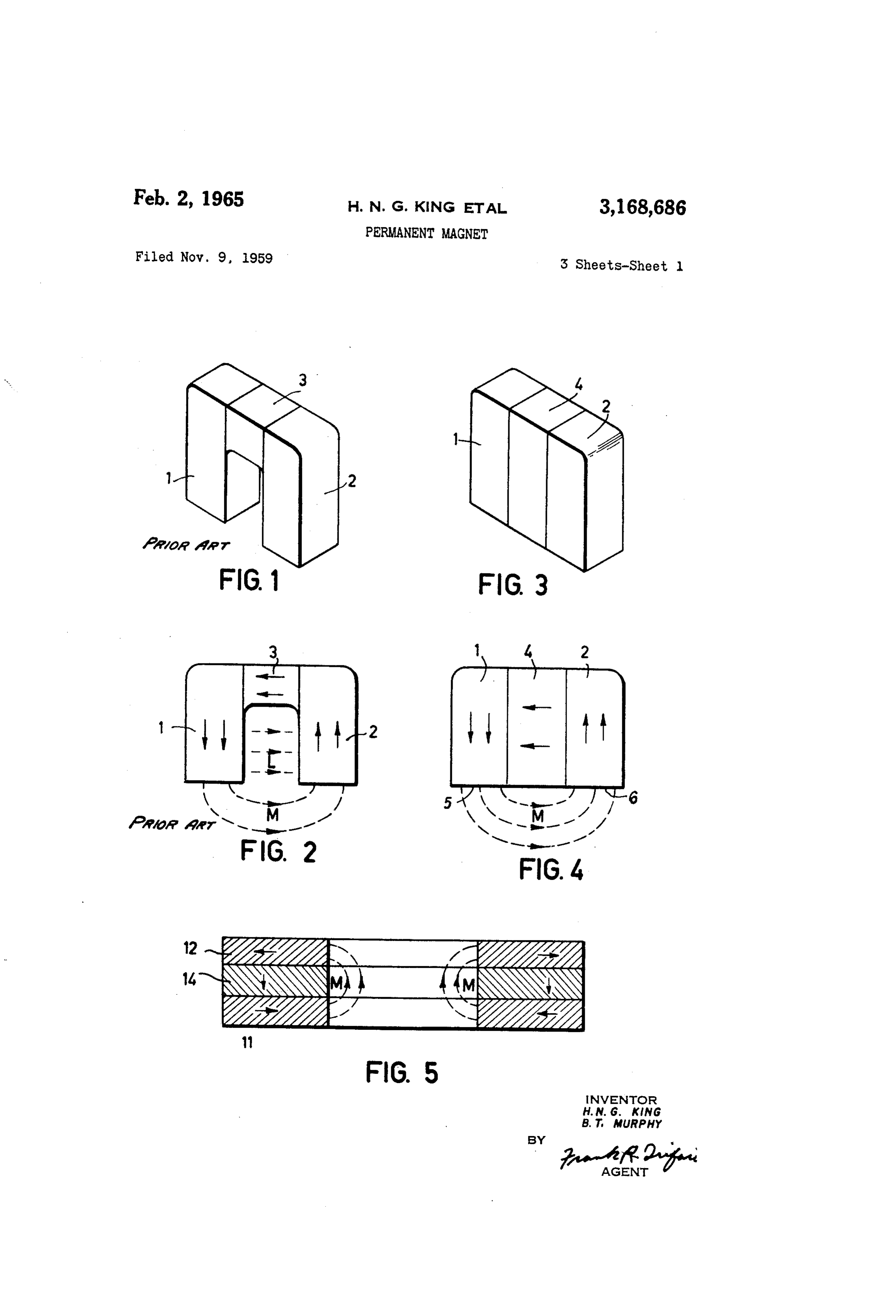
This invention relates to an improved form of perma FiGURE 5 shows a second embodiment comprising an nent magnet body. annuiar magnet body having portions 1 and 12 which According to the invention, a permanent magnet body are radially magnetized and a center portion 14 mag comprises a first permanent magnet and a second perma netized in an axial direction. In a modification, not nent magnet magnetized in substantially opposing direc showil, a body is in the form of a portion of an annulus tions together with a third permanent magnet positioned So that a complete annular arrangement may be built up in contact with and forming a flux path between the first from a plurality of bodies.
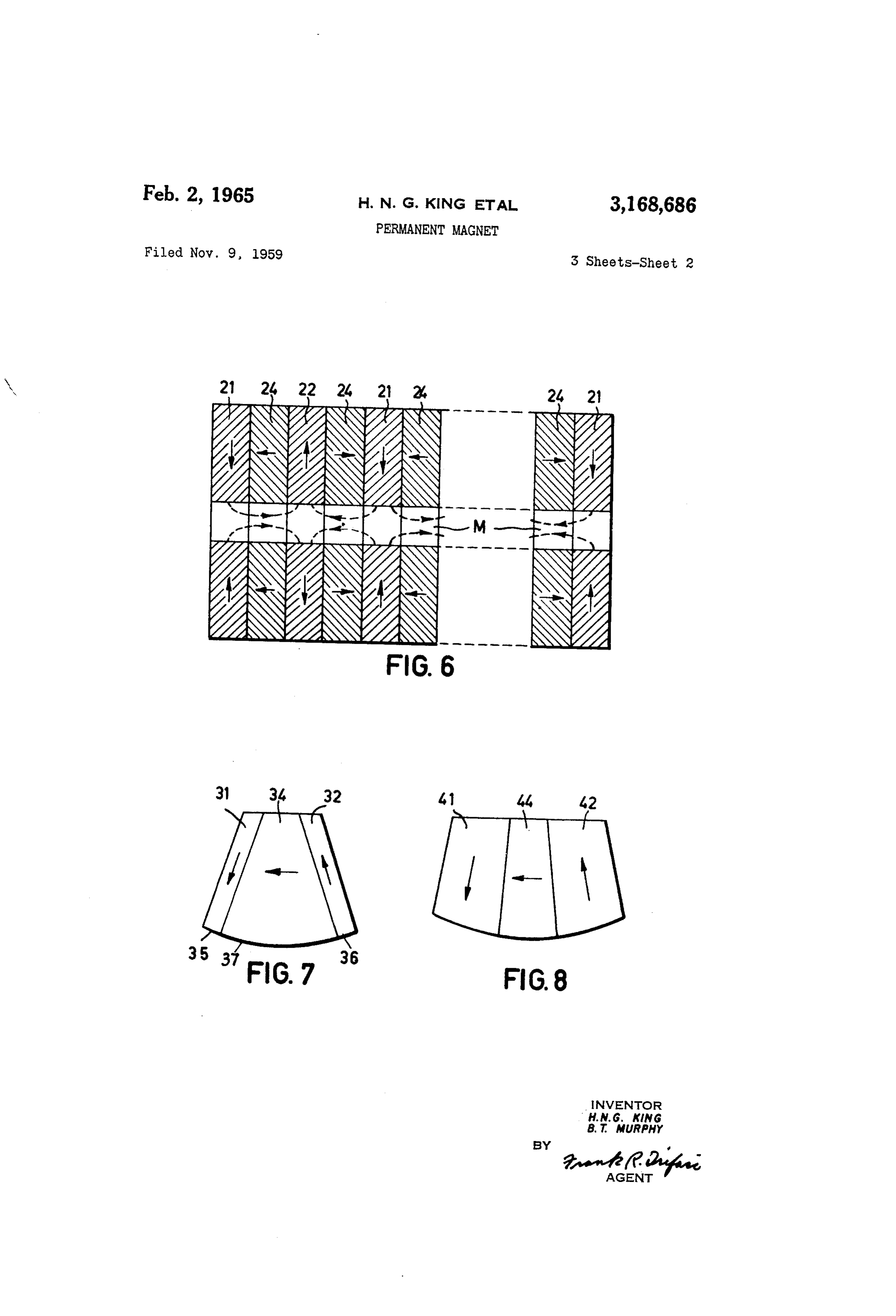
and second permanent magnets, the third permanent mag FiCURE 6 shows an arrangement of ring magnets built net being magnetized in such a direction as to inhibit lip to for in an axial periodic field. Such an arrangement leakage flux from flowing between mutually-facing por is used for focusing an electron beam in a travelling tions of the first and the second permanent magnets. wave tube. In this embodiment rings 21 are radially The first and second magnets may be arranged to pro Inagtnetized in one direction. Rings 22 are radially mag vide on one face of the body a north pole and a south netized in the opposite direction and alternate with the pole, respectively, a surface of the third magnet being rings 2:... Between each adjacent ring 21 and 22 is a positioned to support the north and south poles on the ring 24, the rings 24 being alternately magnetized in op said face. posite axial directions. The field distribution within the The third permanent magnet may be magnetized in a assembly is indicated at M.
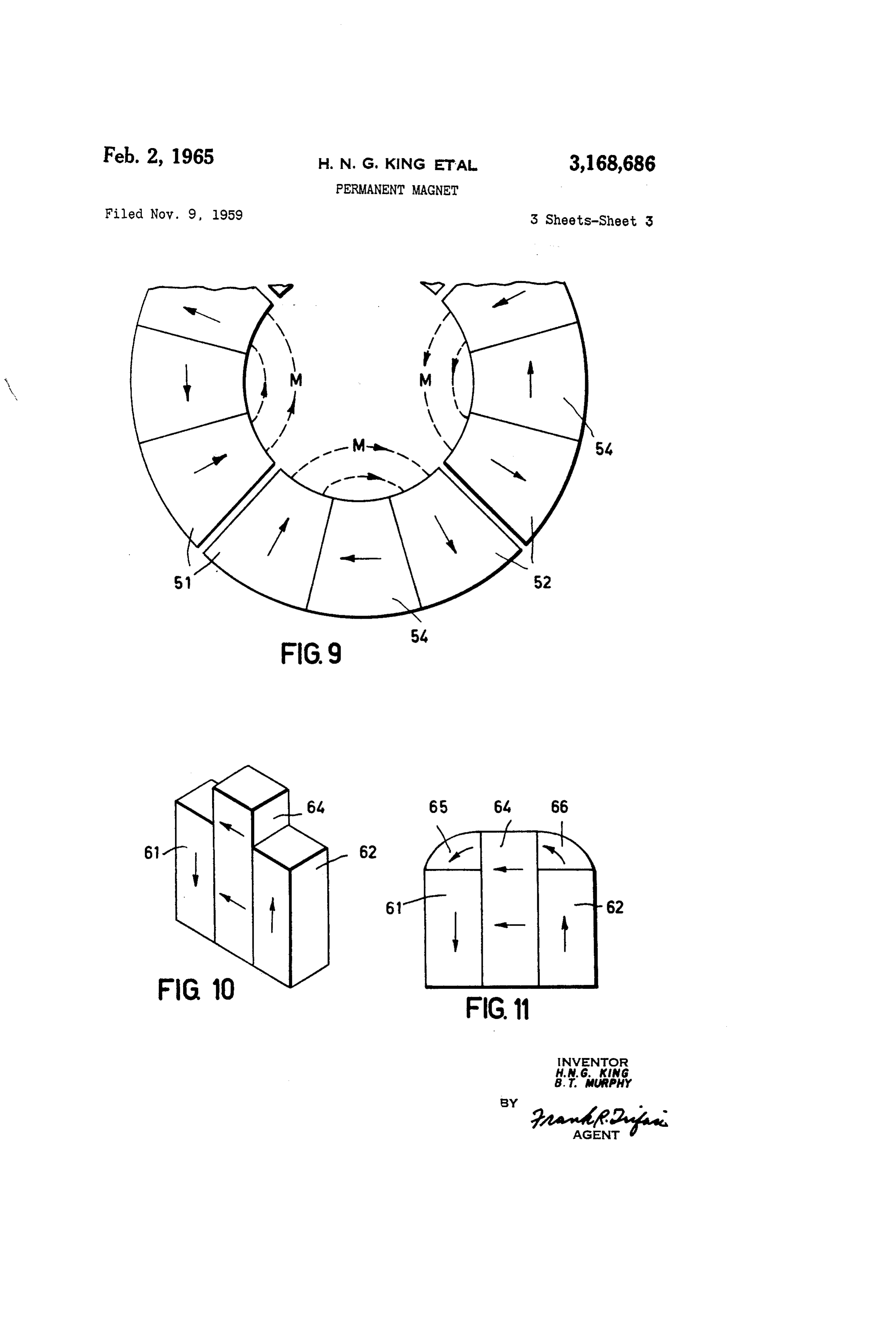
direction substantially perpendicular to the said opposing FiCURE 7 shows an embodiment which is somewhat directions. sinhilar to the embodiment shown in FIGURE 4. In this The face upon which the north and south poles are pro embodiment the opposing directions of magnetization of vided may be a plane. In this case the permanent mag outer limbs 3 and 32 are not parallel, due to the geo net body may have the shape of a parallelepiped. inetirical configuration of the assembly. The surface, to Alternatively, the face upon which the north and south which the opposing magnetization directions of limbs 31 poles are provided may be curved. In this case the per 3 5 and 32 are normal and which is formed by the pole faces manent magnet body may be in the form of an annulus 35 and 36 and the face 37 of the center magnet 34, is or a portion of an annulus. curved instead of being planar as in FIGURE 4. In order that the invention may be readily understood FiSURE 8 is a side view of a further embodiment hav embodiments thereof will now be described with refer ing limb portions 44 and 42 and a center portion 44. ence to the accompanying drawings, wherein: iFiCURE 9 illustrates an embodiment wherein an an FiG. 1 is a perspective view of a known form of per 40 nular magnetic assembly comprises four magnet bodies manent magnet body; each of wirich coinsists of portions 51 and 52, respectively, FiG. 2 is the front view of the permanent magnet body magnetized in opposing radial directions and a portion of FIG. 1; 54 magnetized in a direction perpendicular to the radius FIG. 3 is a perspective view of one embodiment of the and to the axis of the assembly. Such an arrangement is permanent magnet body of this invention; suitable for the field magnet assembly for a small electric FIG. 4 is a front view of the permanent magnet body notor or geneiator.
of FIG.3; FIGURE 10 illustrates an embodiment similar to the F.G. 5 is a cross sectional view of another embodiment embodiment shown in FIGURES 3 and 4. In this em of the permanent magnet body of this invention; bodiment limb portions 61 and 62 are supported by a F.G. 6 is a cross sectional view of still another embodi 50 center portion. 64 which extends beyond the limb por ment of the permanent magnet body of this invention; tions 65 and 62.
FIGS. 7 and 8 are front views of other modified forms FiGURE 11 illustrates a modification of the embodi of the embodiment of FIGS. 3, 4; ment illustrated in FIGURE 10. In this modification FIG. 9 is a partial front view of still another embodi the magnet body comprises limb portions 61 and 62 and ment of the permanent magnet body of this invention; 5 5 a center portion 64 as illustrated in FIGURE 10. The FIG. 10 is a perspective view of still another embodi spaces between the upper ends of the limb portions 61 ment of the permanent magnet body of this invention; and 62 and the upper said faces of the center portion 64 and are filed in by means of shaped members 65 and 66. FIG. 11 is a front view of a modified form of the en 60 These members 65 and 66 may be of a soft magnetic ma bodiment of F.G. 10. terial or alternatively they may be of permanent magnets, Referring to FIGURES 1 and 2 a known form of per in which case they would preferably, but not necessarily, manent magnet body comprised two limbs and 2, and a be magnetized in the directions indicated by the curved center portion 3 magnetized in the directions indicated by aCWS.
the arrows. With this arrangement leakage flux L will What is claimed is:
flow between adjacent side faces of the limbs and 2 so 1. A permanent magnet comprising a body having that the total flux is greater than the useful main flux M. three adjoining and aligned permanent magnet portions Referring now to FIGURES 3 and 4, a parallelepiped forming along one face of the magnet a substantially con permanent magnet body comprises limb portions 1 and tinuous surface, the outer two magnet portions being 2 which in this example may be regarded as being sub magnetized in substantially opposite directions substan stantially identical with the limbs 1 and 2 in FIGURES 1 tially orthcgonally to the said one face, the center mag and 2 and which are magnetized in the same direction as net portion being magnetized in a direction substantially
Page 5
at right angles to the imagnetizing directions of the oilter having first and second end permanent magnet portions magnet portions and in a plane Substantially parallel to and a third intermediate permanent magnet portion in the plane defined by the magnetizing directions of Said adjoining relationship with each of said first and Second outer two magnet portions, the magnet producing a strong, magnet portions, said first, second and third magnet por useful external field adjacent the said one face. 5 tions being aligned to form at least one face of said body, 2. A permanent magnet comprising at least one body said face having a substantially continuous surface with a having first and second end permanent magnet portions predetermined degree of curvature greater than Zero, said and a third intermediate permanent magnet polition i 4.
first and second permanent magnet portions being mag adjoining relationship with each of Said first aid second netized in substantially opposite directions normal to said magnet portions, said first, second and third magn gnet por O surface, and said third intermediate magnet portion being tions being aligned to form at least one face of said body, magnetized in a direction substantially normal to the said face having a substantially continuous Surface with magnetizing directions of said first and second magnet a predetermined degree of curvature, said first and second portions and in a plane substantially parallel to the plane permanent magnet portions being magnetized in substai defined by the magnetizing directions of said first and tially opposite directions normal to said surface, and said second magnet portions, said magnet providing a mag third intermediate magnet portion being magnetized in a etic field adjacent to said one face. direction substantially normal to the magnetizi or ri ec st -- 16. A permanent magnet comprising at least one body tions of said first and second magnet portions 2. in a having first and second end permanent magnet portions plane substantially parallel to the plane define and a third intermediate permanent magnet portion in magnetizing directions of said first and second naga adjoining relationship with each of said first and second tions, said magnet providing a magnetic field adjacent t O magnet portions, said first, second and third magnet por said one face. tions being aiigned to form at east one face of said body, said face having a substantially continuous convex sur face, said first and second permanent magnet portions and a third intermediate permanent magnet portio; in 2 5 being magnetized in substantially opposite directions nor joining relationship with each of said first and nial to said surface, and said third intermediate magnet portion being magnetized in a direction substantially tions being aligned to form at least one face of said normal to the magnetizing directions of said first and said face having a substantially continuous surface Second magnet portions and in a piane substantially paral substantially a zero degree of curyatire, said lel to the plaine defined by the magnetizing directions of second permanent magnet portions being magnetize: said first and second magnet portions, said magnet pro substantially opposite directions normal to said surface, viding a magnetic field adjacent to said one face. 11. A permanent magnet comprising at least one body having the composite form of a circumferential section netizing directions of said first and second magnet portions of a given annulus, said circumferential section having a and in a plane substantially parallel to the plane de predetermined angular length, said body comprising first by the magnetizing directions of Said first and second mag and second end permanent magnet portions and a third net portions, said magnet providing a magnetic field ad intermediate permanent magnet portion in adjoining re jacent to said one face. lationship with each of said first and second magnet por 4. A permanent magnet comprising a body in the 40 tions, each of said first, second and third magnet portions form of a parallelepiped and comprising first and second having the form of a circumferential section of prede end permanent magnet portions and a third intermediate termined angular length of said given annulus and being permanent magnet portion adjoining each of Said first aligned with respect to each other to form said composite and second magnet portions, said first, second and third ly formed body, said portions having the respective con magnet portions being aligned to form along one face 4. 5 cave circumferential surfaces thereof being aligned to of the magnet a substantially continuous surface arid form the concave circumferential face of said annulus each having respective longitudinal axes thereof normal Section compositely formed body, each of said first and to said one face, said first and Second perinaient magnet Second permanent magnet portions being magnetized in portions being magnetized in substantially opposite direc Substantially opposite directions normal to said face, and tions normal to said one face, and said third interinedi 5 said third intermediate magnet portion being magnetized ate magnet portion being magnetized in a direction sub in a direction substantially normal to the magnetizing stantially normal to the magnetizing directions of said directions of Said first and second magnet portions and rst and second magnet portions and in a plane substan in a plane substantially parallel to the plane defined by tially parallel to the plane defined by the magnetizing the magnetizing directions of said first and second mag directions of said first and second magnet portions, said net portions, said magnet providing a magnetic field ad magnet providing a useful magnetic field adjacent to jacent to said one face.
said one face. 12. A permanent magnet according to claim 11 where 5. A permanent magnet according to claim 4 wherein in Said three magnet portions are aligned in substantially said first, second and third naginet portions have respec the same plane, said last mentioned plane being substan tive said longitudinal axes of substantially equai lengths. 60 tially normal to the center axis of said given annulus. 6. A permanent magnet according to claim 4, wherein 13. A permanent magnet according to claim 11 where said first and second magnet portions have respective said in Said three magnet portions are in mutually exclusive longitudinal axes of substantially equal lengths, and said planes, each of said mutually exclusive planes being sub third magnet portion has a respective said longiii.2ginal Stantially normal to the center axis of said given annulus. axis greater than the length of said longitudinai axis of 14. A permanent magnet comprising an apertured an each of said first and second magnet portions winich nular body having a center axis and comprising at least causes said third magnet portion to have a projection three adjoining and axially-aligned permanet magnet an which extends past said first and second portions. nular portions forming along the face of the magnet 7. A permanent magnet according to claim 6 further bounding the aperture a substantially continuous sur comprising ferromagnetic material in adjoining relation O face, the first and third magnet portions being magnetized ship with the projection of said third portion and each in Substantially opposite directions substantially ortho of said first and second portions. gonally to the said one face, the second magnet portion 8. A permanent magnet according to claim 7 wherein being intermediate said first and third magnet portions said ferromagnetic material is periaanently magitetic. and magnetized in a direction substantially at right angles 9. A permanent magnet comprising at least one body to the magnetizing directions of the first and third mag
Page 6
S s
net portions, said magnet providing a useful magnetic in a plane substantially parallel to the plane defined by field adjacent to said one face. the magnetizing directions of Said first and second mag 15. A permanent magnet for producing an internal net portions, said magnet providing a magnetic field ad periodically reversing magnetic field, comprising a stacked jacent to said one face.
array of magnets as claimed in claim 14, wherein the i.7. A permanent magnet network according to claim odd-numbered magnets are magnetized radially and in op i5 wherein said bodies are aligned substantially in the posite senses, and the even-numbered magnets are mag same plane and the total angular length of the respective netized axially and in opposite senses. concave surfaces thereof is substantially 360 degrees, said 16. A permanent magnet network having a body last mentioned plane being substantially normal to the adapted to be aligned with other similar bodies as associ 0 axis of origin of said concave surfaces. ated parts of said permanent magnet network, each of said bodies comprising first and second end permanent References Cised in the file of this patent magnet portions and a third intermediate permanent mag UNTE SATES PATENTS net portion in adjoining relationship with each of said first and second magnet portions, said first, second and 5 2,722,617 Cluwen et al. ------------ Nov. 1, 1955 third magnet portions being aligned with respect to each 2,727,650 Maynihan et al. ---------- Dec. 20, 1955 other to form at least one face of said body, said face 2,830,207 Clark ------------------- Apr. 8, 1958 having a substantially continuous concave surface of a 2,908,329 Weber ------------------ Sept. 8, 1959 predetermined angular length, said first and second per 2,972,485 Ferchland -------------- Feb. 21, 1961 y manent magnet portions being magnetized in substantially 20 2,981,871 Westmijze -------------- Apr. 25, 1961 opposite directions normal to said concave surface, and FOREIGN PATENTS said third intermediate magnet portion being magnetized 768,518 Great Britain ----------- Feb. 20, 1957 in a direction substantially normal to the magnetizing 216,080 Austria ---------------- July 17, 1958 directions of said first and second magnet portions and
Provenance
- Collection
- Cited prior art
- Original PDF
- patentimages.storage.googleapis.com →
- Filed
- 1959-11-09
- Pages
- 6
- Method
- pdftotext (the PDF's own text layer) + pdftoppm 300dpi page scans
- Source
- Google Patents bibliographic record
- Granted
- 1965-02-02
- Inventors
- King Hewson Nicholas Graham; Murphy Bernard Thomas; US Philips Corp
- Transcribed from
- patentimages.storage.googleapis.com →