patent · US2496897
Bearing and seal assembly for turbines
7 February 1950
Page 1
Feb. 7, 1950 H. R. STRICKLAND 2,496,897
BEARING AND SEAL ASSEMBLY FOR TURBINES
Filed Aug. 23, l944 2 Sheets-Sheet l
Esess
As) - N 2 - SS (9) - t s T- w x - O - Š o
SNS
M W to cy
--wr---- W v d
2-R c N
Page 2
Drawing sheet — no readable text.
Page 3
Patented Feb. 7, 1950 2496,897
BEARNG AND SEA, ASSEMBLY
FoRTURBINEs
Henry R. Strickland, Hartford, Conn., assignor to
United Aircraft Corporation, East Eartford,
Conn., a corporation of Delaware
Application August 23, 1944, Serial No. 550,902
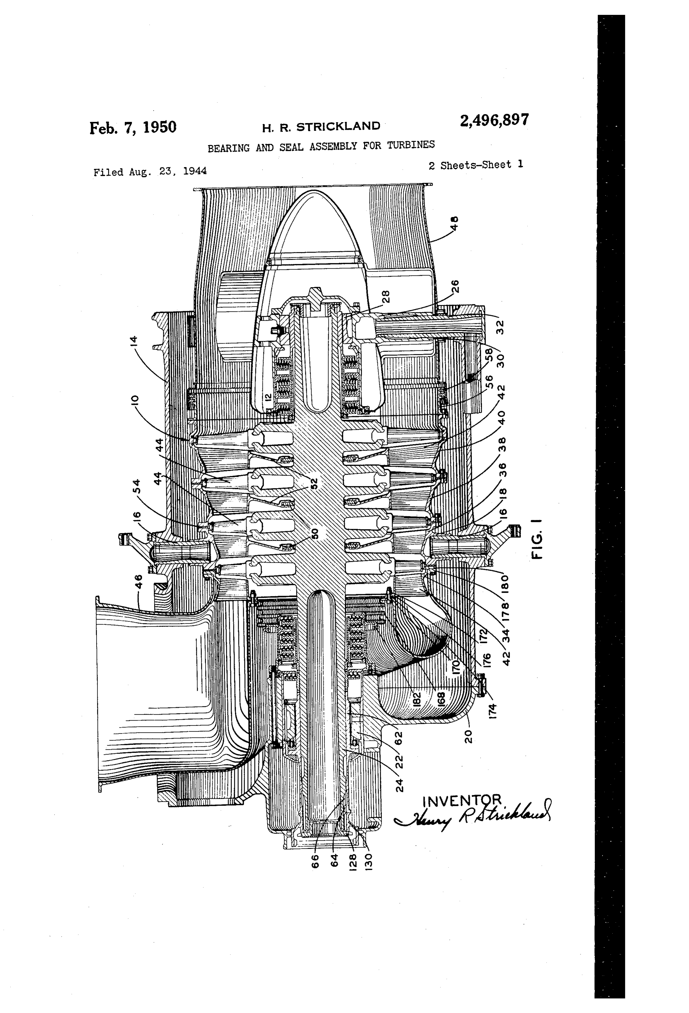
This invention relates to a bearing and seal f8 are all on ring 36 so that the supporting pins assembly for a turbine and is directed particul all engage the same ring. An inlet scroll 4 di larly to an assembly for use in an elastic fluid rects the driving fluid through the row of nozzles turbine. on the first casing ring 34 and an exhaust duct The use of the Ljungstrom type of labyrinth A8 guides the driving fluid from the last row of seal is advantageous where space is limited. blades on the rotor.
These seals must, however, be assembled axially The turbine is made with substantially all of by reason of the interengaging cylindrical the pieces unsplit or continuous for ease of flanges. A feature of this invention is a seal machining and to assist in reducing the leakage assembly by which the elements of the seal may 0. losses to permit assembly of the casing around be axially assembled as a unit and held in posi the solid rotor. Casing rings 36, 38 and 40 are tion when assembled. Another feature is the use split and are bolted together and to each other of face splines for locking the elements of the in the assembly of the turbine. Diaphragm seals seal against relative rotation. 50 carried by the diaphragms 52 of these casing Another feature of the invention is a bearing 5 rings are also split to permit assembly on the assembly including a plain bearing and a thrust rotor. Seals 54 in line with the rows of blades bearing both forming a unitary sub-assembly. on the rotor are clamped between adjoining cas Another feature is an oil seal forming a part of ing rings and, as will be apparent, these seals
the seal assembly.
Beyond casing ring 40 is a ring 56 which
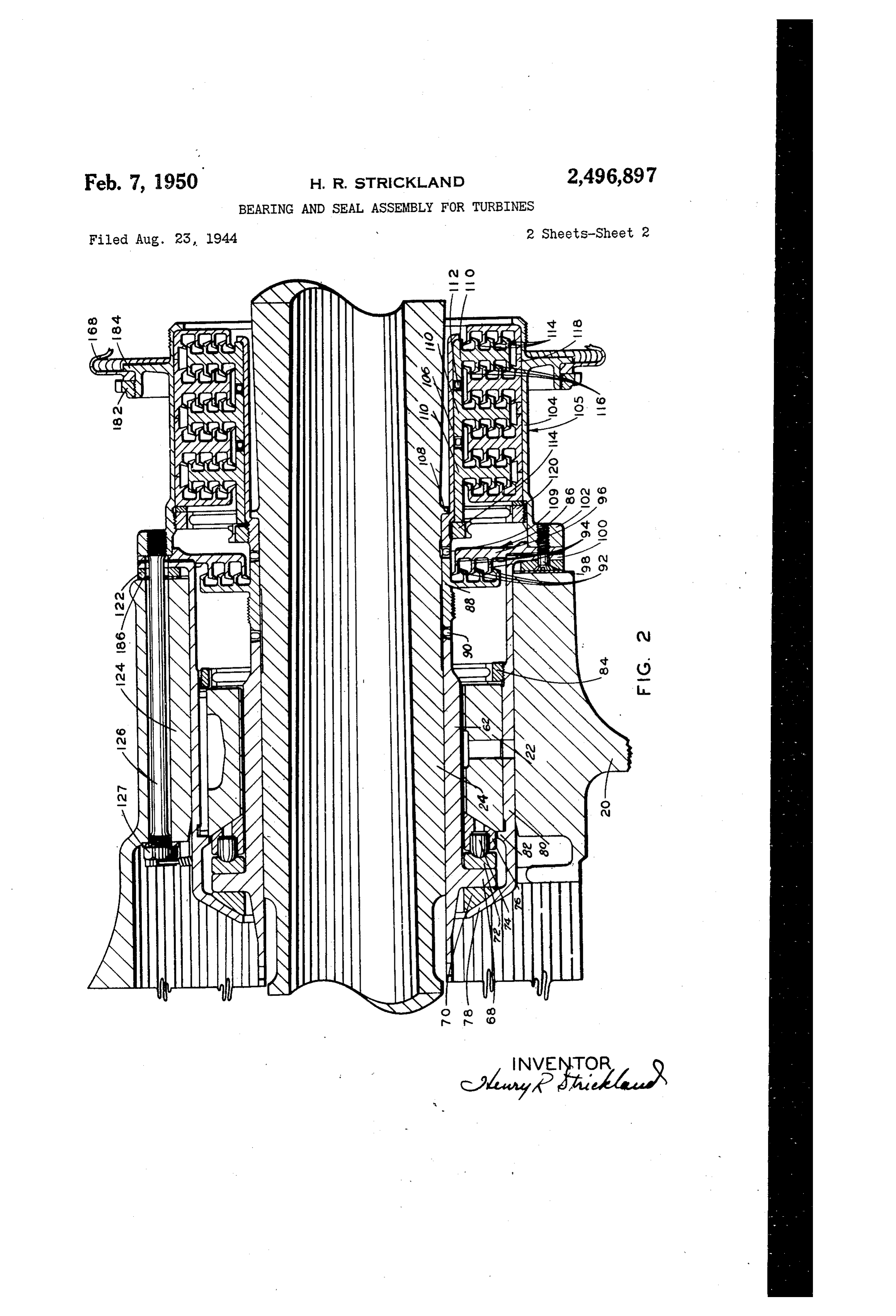
A feature of the invention is the unitary as 20 carries sembly of a labyrinth seal and the bearing struc rings 58 engaging the leading end of the ture all of which may be mounted on the shaft as exhaust duct. The latter is located by the same a unit. Another feature is the piloting and pins 32 that locate the rear bearing support. The front bearing and seal are assembled as a mounting of this assembly in the supporting housing. 25 unit. As shown in Fig. 2 the bearing 22 engages Other objects and advantages will be apparent with Fig. a sleeve 62 having splines 64 at its outer from the specification and claim, and from the end, 1, engaging with cooperating splines 66 on the turbine shaft. Sleeve 62 forms a bear accompanying drawings which illustrate an en bodiment of the invention. ing surface for the turbine shaft and has a pro Fig. 1 is a sectional view through the turbine. jecting rib 68 one surface of which engages with Fig. 2 is a fragmentary sectional view on a a bearing ring 70 and the other surface of which larger Scale of the front bearing and seal. engages a number of thrust shoes 72 carried by The turbine includes a casing it and a rotor pins 4 in a ring 76 engaging the end of bearing 42 both supported in a housing 4. The casing 22. The opposite surface of rings 70 and 76 may is supported by radially extending pins 6 carried 3 5 be spherical to accommodate bending of the by the housing and engaging bores in bosses 8 rotor. Bearing ring 70 engages with an inturned on the casing. These pins are all in substan flange 78 on a sleeve 80 which also supports bear tially the same plane and constitute the sole ing 22 between a projecting rib 82 and a ciamping support for the casing so that the casing is free ring 84. With the ring 84 in place the bearing to expand lengthwise. In the plane of the pins 40 ring 70, the thrust bearing, and bearing 22 are the casing is smaller than the housing and clear held in assembled relation with sleeve 62. A ance is provided at the inner ends of pins 6 to of these parts may be continuous. permit the casing to expand radially. Adjacent to bearing 22 and between this bear Housing 6 has a head 20 which forms a part ing and the power section of the turbine is an oil of the housing and supports a bearing 22 for the 45 Seal 86 including a sleeve 88 fitting on shaft 24 front end of the turbine shaft 24 forming an in and having face splines 90 engaging with co tegral part of the rotor. At the other end of the operating Splines on the end of sleeve 62. Sleeve housing a spider 26 supports a bearing 28 for 88 carries radially spaced sealing elements 92 co the turbine shaft. The spider has a number of operating with similar elements 94 on a stationary legs 20 engaging radially positioned pins 32 unSplit disk 96 clamped by screws 98 between a carried by the housing. flange 00 on sleeve 80 and a flange 02 on a Casing C is built up of several rings 34, 36, 38 sleeve 04 that Supports the stationary elements and 40, each of which has a single row of nozzle of a labyrinth seal OS which is located between forming guides 42. These rows of guides alter the oil seal and the power section of the turbine. nate with rows of biades 44 on the rotor. Bosses The labyrinth seal is made of unsplit pieces.
Page 4
The seal includes an inner sleeve S having a 4. shoulder engaging a projecting rib permit attachment of the scroll and nozzle ring on shaft directly to the second stage nozzle ring . The 24. The end of sleeve to may have face splines outer end of the flexible seal B is clamped by engaging with cooperating splines on the a ring 2 against a shoulder f4, Fig. 2, project inner end of sleeve 8. The inner end of sleeve ing from sleeve 4.
B is out of engagement with turbine shaft 24 The casing and inlet scroll together with the to prevent direct transmission of heat from the front and rear bearing and seal assemblies hav shaft to the sea, Sleeve 0 supports a number ing been mounted on the rotor, and housing 4 of spaced sealing elements to having cylindrical mounted in place by the pins 4, the spider 2 openings for receiving sleeve fo and having in O being located by the pins 82, cap 2 fastened terengaging face splines f2 at their adjoining to housing f4 and the front bearing and seal edges. The elements flo are locked in position assembly is located in predetermined relation to between an outwardly extending flange on the inner end of sleeve 106 and a clamping ring 4 tion of the rotor with f2.
the cap by the studs Accurate axial loca respect to the casing may which, as shown, engages the sleeve 6 adjacent 5 be obtained by a washer fit between spacer ring its outer end. Each of elements ff0 has a num 22 and the end of sleeve 24. ber of projecting cylindrical flanges 4 cooperat It is to be understood that the invention is not ing with similar sealing flanges 6 carried by limited to the specific embodiment herein illus elements 8 fitting within sleeve 04. The ele trated and described, but may be used in other ments f have outer cylindrical surfaces engag 20 ways without departure from its spirit as defined ing sleeve 04 and are clamped in position be by the following claim.
tween an inturned flange on sleeve 04 and a claim: .
clamping ring 20, the latter engaging sleeve fo A bearing assembly including a sleeve adapted adjacent its outer end. to be mounted on a rotary shaft and having a The labyrinth seal may be assembled as a unit. projecting flange, a stationary bearing support The elements of the oil seal may then be placed around the sleeve and having a cylindrical outer in position at the end of the labyrinth seal, and Surface, a main bearing mounted in the support the bearing assembly is then connected to the and engaging Said sleeve, a clamping ring within Seal assembly by the screws 98. A spacer ring 22 may be clamped against flange 00 by the 30 for support the and engaging the end of said bearing holding said bearing in the support, and screws 98. The front bearing and seal assembly thrust bearing elements carried by the support is held in place within a sleeve f24 by studs 26 and engaging opposite surfaces of said flange, engaging flanges f2. These studs have clamp one of Said thrust bearing elements being sup ing nuts 27 accessible at the outer end of sleeve ported axially by the end of said main bearing. 24. Sleeve 24 is an integral part of head 20. 35 HENRY R. STRICKLAND. Referring to Fig. 1, sleeve 62 may be clamped securely on the turbine shaft by a threaded REFERENCES CTE) clamping ring 28 which clamps a splined sleeve The following references are of record in the 30 against the end of sleeve 62. This sleeve 80 also holds sleeves 88 and 06 in position on the 40 file of this patent:
shaft. UNITED STATES PATENTS The unsplit first stage nozzle ring 34 together Number Name Date with the inlet scroll and a flexible seal 68 are 1,158,424 Banner ------------ Nov. 2, 1915 attached to the rest of the casing as a sub-assem 1,609,496 Reed -------------- Dec. 7, 1926 bly. The nozzle ring has previously been con 45 1,712.277 McIntyre ----------- May 7, 1929 nected to an inner flange fo on the inlet scroll 1,762,117 Dahlstrand --------- June 3, 1930 by bolts 72 which extend through flange 70, 1,774,655 Messinger ---------- Sept. 2, 1930 a flange T4 on the flexible seal, and a flange 1918,988 Searles et al. ------- July 18, 1933 76 extending inwardly from Casing ring 84. An 2,040,218 Soderberg --------- May 12, 1936 outer flange f78 on the inlet scroll and a co 50 2,410,340 Cronstedt --------- Oct. 29, 1946 operating flange 80 on the first stage nozzle
Provenance
- Collection
- Cited prior art
- Original PDF
- patentimages.storage.googleapis.com →
- Filed
- 1944-08-23
- Pages
- 4
- Method
- pdftotext (the PDF's own text layer) + pdftoppm 300dpi page scans
- Source
- Google Patents bibliographic record
- Granted
- 1950-02-07
- Inventors
- Henry R Strickland; United Aircraft Corp
- Transcribed from
- patentimages.storage.googleapis.com →