patent · US5281094
Electromechanical apparatus for varying blade of variable-pitch fan blades
25 January 1994
Page 1 — bibliographic record
United States Patent (19) (11) Patent Number: 5,281,094 McCarty et al. 45) Date of Patent: Jan. 25, 1994 54 ELECTROMECHANCAL APPARATUS FOR 4,534,524 8/1985 Aldrich . WARY ING BLADE OF WARIABLE-PTCH 4,578,019 3/1986 Safarik . FAN BLADES 4,640,668 2/1987 Yang .
75 Inventors: Frederick B. McCarty, San Pedro; 4,682,094 7/1987 Kuroiwa . Leroy A. Fizer, Huntington Beach; 4,757,240 7/1988 Mizobuchi et al. . Daniel E. Wilson, Wilmington; 4,895,005 1/1990 Norbeck et al. . Kenneth L. Wuertz, Torrance, all of 4,916,368 4/1990 Onoda et al. . Calif. 4,965,477 10/1990 Stadler et al. .
(73) Assignee: AlliedSignal Inc, Morris Township, FOREIGN PATENT DOCUMENTS Morris County, N.J. 3406634A1 8/1985 Fed. Rep. of Germany . 21) Appl. No.: 949,295 OTHER PUBLICATIONS 22 Filed: Sep. 22, 1992 "Direct and Alternating Current Machinery' 2nd Edi tion by Jack Rosenblatt and M. Harold Friedman:
Related U.S. Application Data Chapter 17 Polyphase Induction Motor, pp. 265-266, 63 Continuation-in-part of Ser. No. 699,399, May 13, Chapter 18 pp. 349-351,358-360. 1991, abandoned. Primary Examiner-John T. Kwon (51) Int. Cl.............................................. FO4D 29/36 Attorney, Agent, or Firm-Joseph R. Black; Robert A. 52 U.S. C. .................................... 416/147; 416/159; Walsh
416/159, 25, 170R, 3, 155, 156; 318/722, 723 Blade pitch of variable pitch blades is changed by an 56 References Cited actuator having first and second ac machines. The first ac machine is excited with ac power to apply a motor
1,951,320 3/1934 Blanchard . causing blade pitch to change in one direction. The 2,346,007 4/1944 Chillson . second ac machine is excited with appropriate power to 2,370,135 2/1945 Berliner . apply a braking torque to the control shaft, thereby 2,488,392 11/1949 Forsyth . causing blade pitch to change in an opposite direction. 2,490,329 12/1949 Wilde, Jr. . When the second ac machine is an induction machine, 2,612,228 9/1952 Forsyth . dc excitation will brake the control shaft. When the 2,705,537 4/1955 Nichols . second ac machine is a synchronous machine, an ac
3,900,274 8/1975 Johnston et al. ............... 46/160 X excitation causing a retarding magnetic field will brake 4,338,525 7/1982 Kilgore . the control shaft.
4,464,579 8/1984 Schwarz . 18 Claims, 4 Drawing Sheets
Eta COE
Page 2
Drawing sheet — no readable text.
Page 3
Drawing sheet — no readable text.
Page 4
Drawing sheet — no readable text.
Page 5
Drawing sheet — no readable text.
Page 6
changed in one direction and for providing a second
ELECTROMECHANCAL APPARATUS FOR excitation when blade pitch is to be changed in an oppo VARYNG BLADE OF WARABLEPTCH FAN site direction. The apparatus further comprises torque BLADES means for applying torques to the control shaft in re CROSS-REFERENCE TO RELATED sponse to the first and second excitations. The torque APPLICATION means provides a motoring torque in response to the first excitation and a braking torque in response to the
This is a continuation-in-part of application Ser. No. second excitation.
07/699,399 filed on May 13, 1991, now abandoned. The torque means can include at least one ac machine FIELD OF THE INVENTION O having a rotor and a stator. The disadvantages discussed This invention relates in general to actuation systems above with are overcome by securing the rotor for rotation the control shaft and by securing the stator, which for gas turbine engines and in particular to ac machines includes the power windings, to a non-rotational struc for varying the blade pitch of variable-pitch fan blades. 15 ture of the engine. Thus, the power windings can be BACKGROUND OF THE INVENTION connected to a stationary power supply. Further, the Turbofan engines have proven to be desirable for blades rotate.
can be feathered even if the fan shaft does not aircraft that travel at subsonic speeds. A turbofan en gine utilizes energy from a jet stream of gas to turn a BRIEF DESCRIPTION OF THE DRAWINGS turbine shaft. The shaft turns a ducted fan assembly 20 FIG. 1 is a perspective view of a ducted fan propul whose blades move a mass of air, providing a thrust that propels the aircraft. The thrust is varied by changing sion unit;
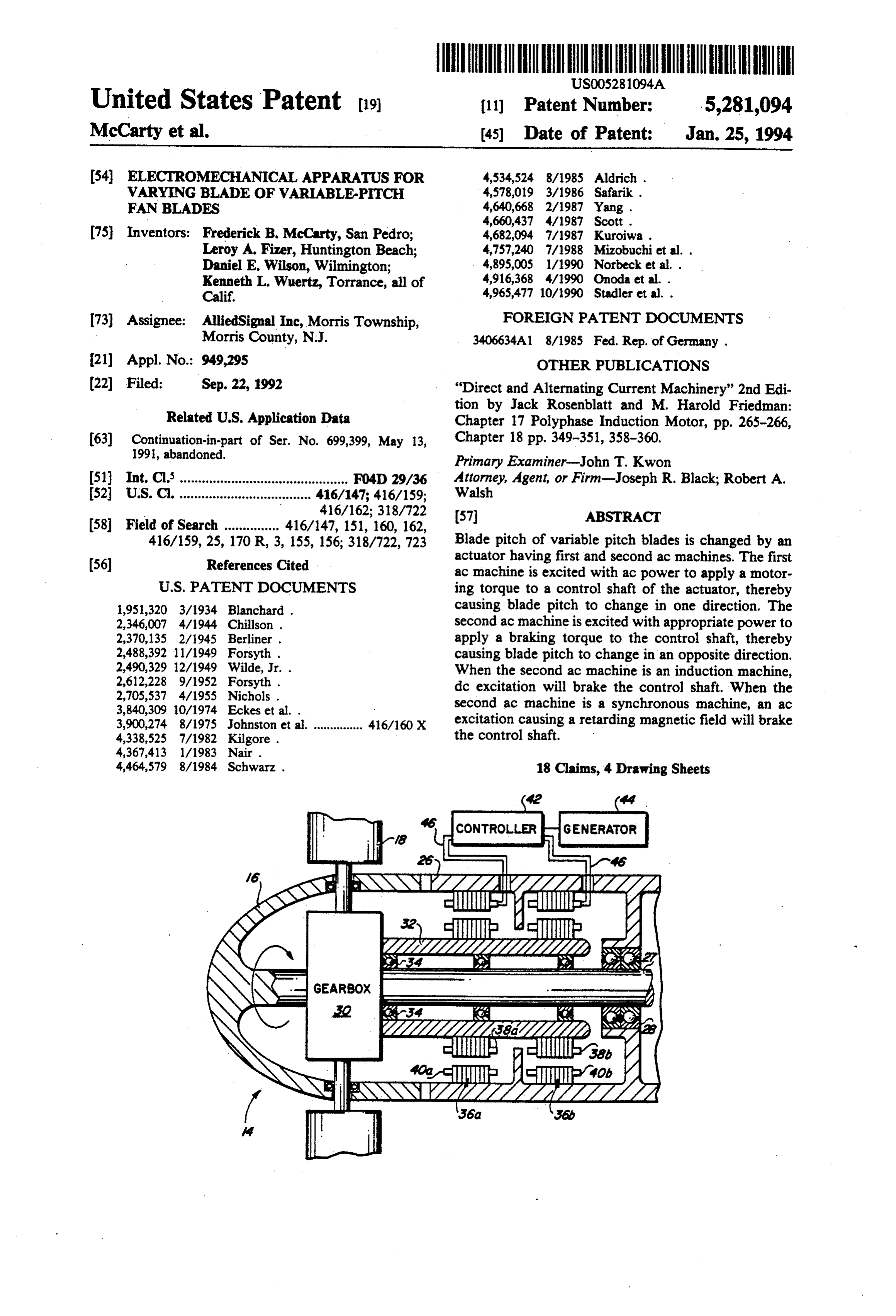
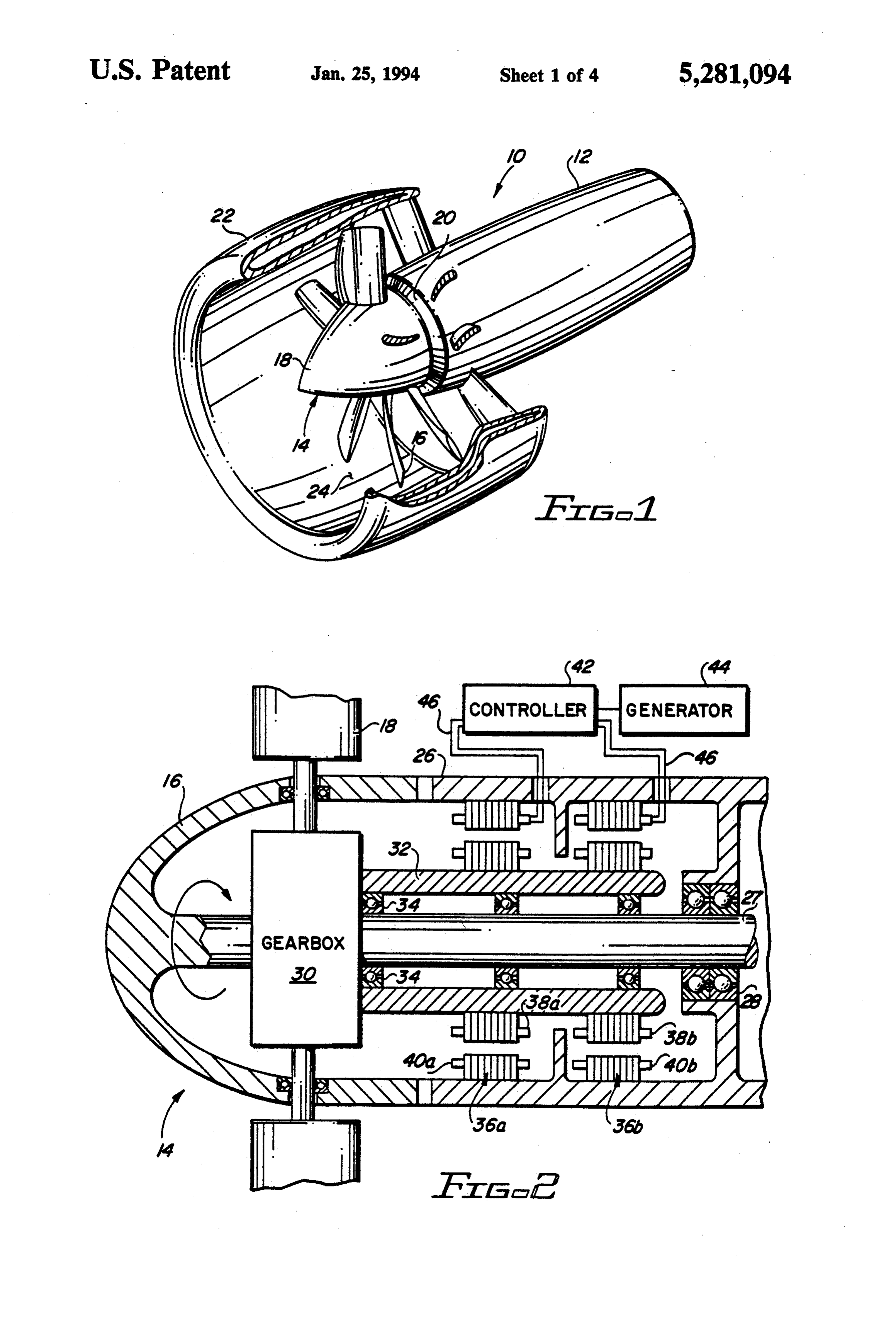
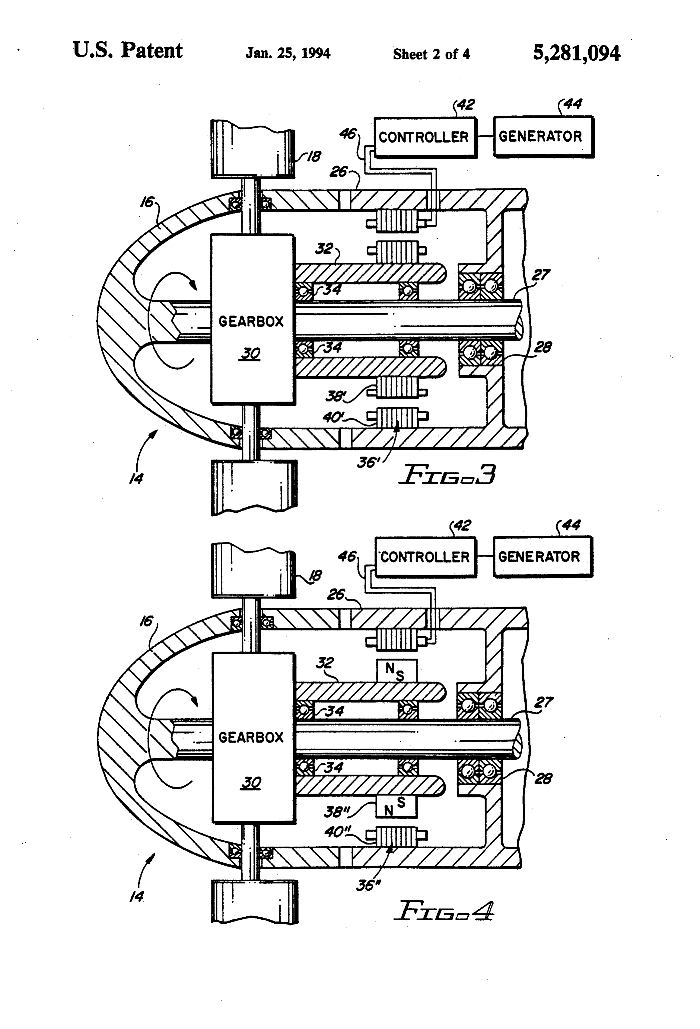
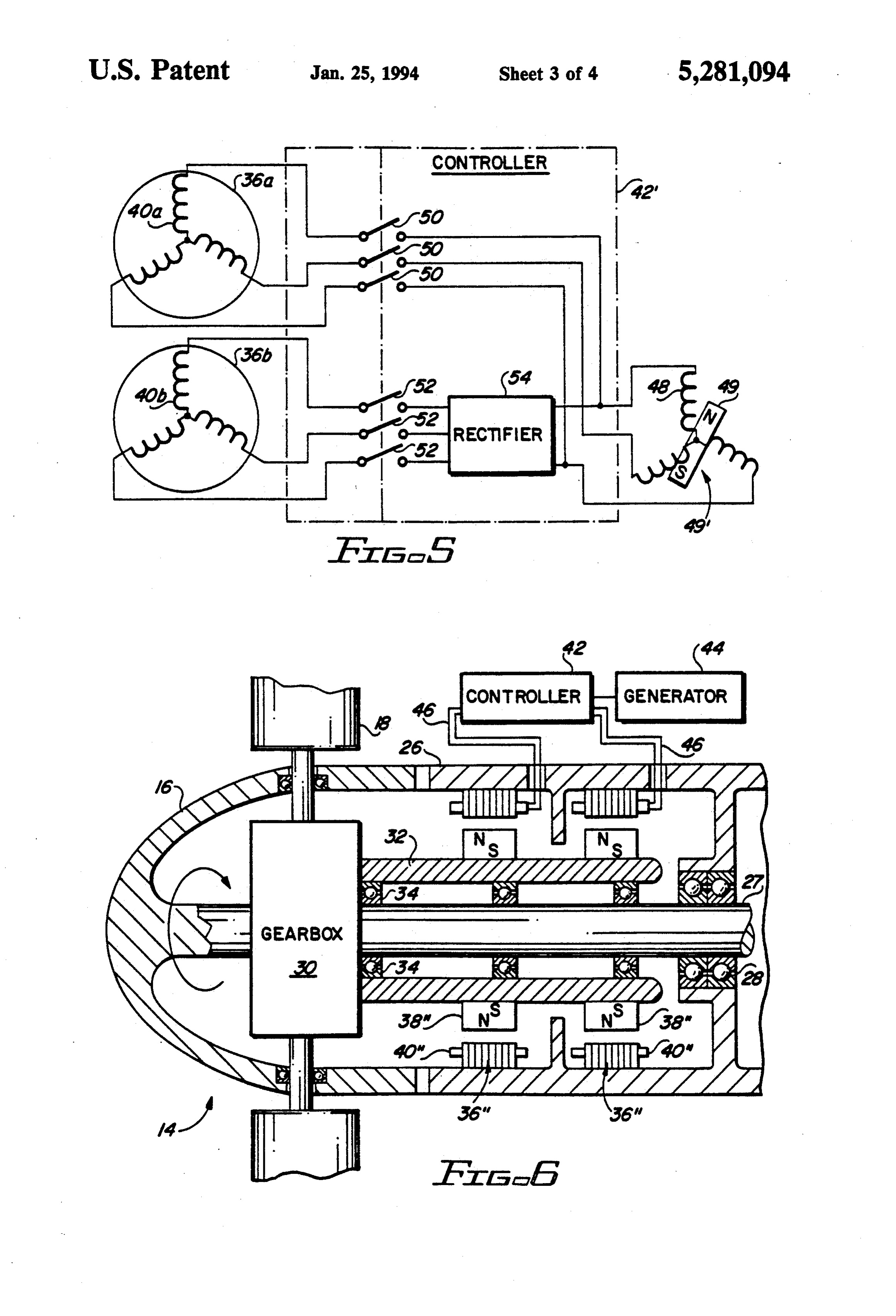
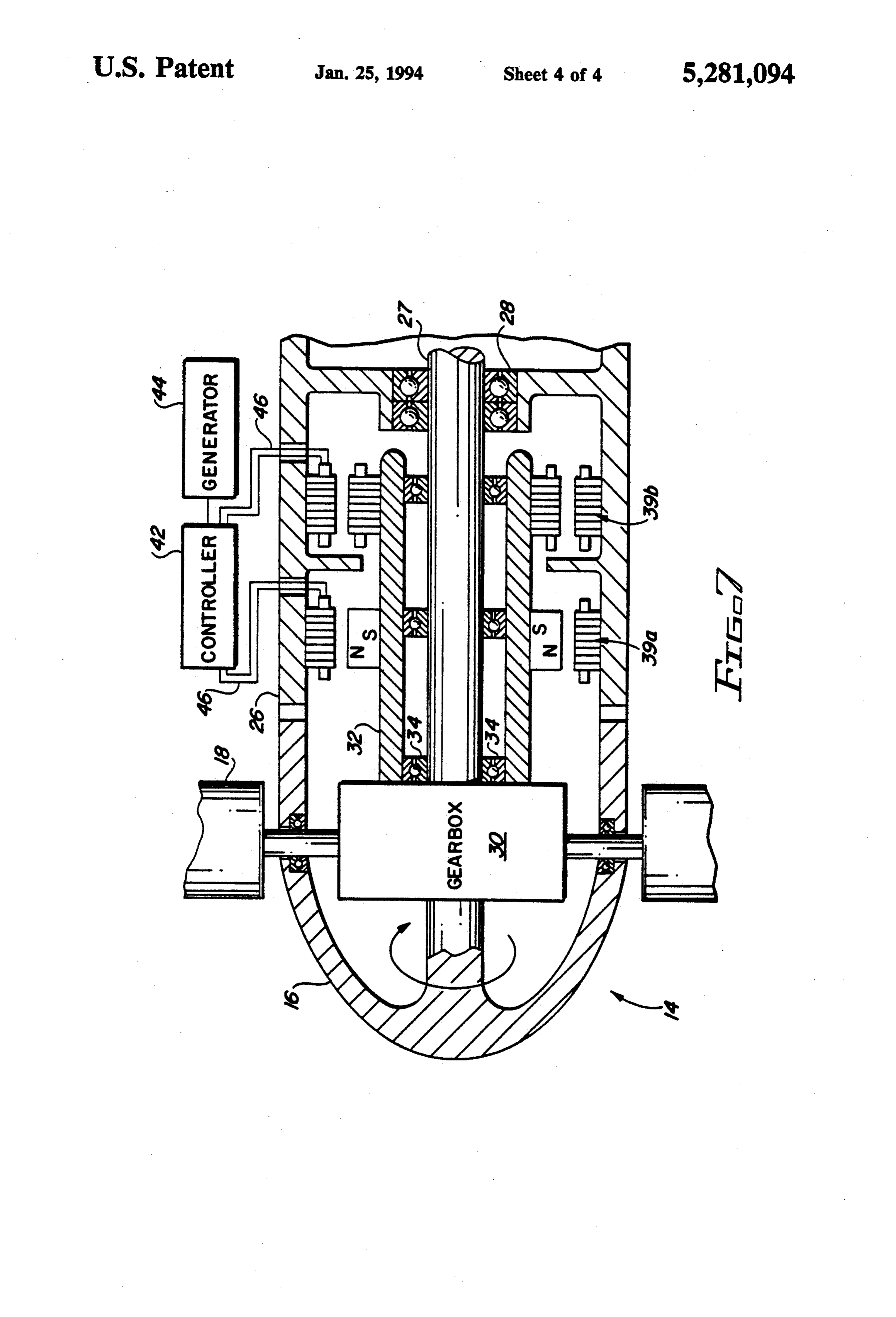
the pitch of the fan blades. During takeoff, when high FIG. 2 is a schematic of a preferred embodiment of an thrust is required, the pitch of the blades is adjusted to actuation system according to this invention; and produce maximum engine torque. At cruise, when 25 FIG. 3 is a schematic of another embodiment of an lower speeds are required, the blade pitch is adjusted to actuation system according to this invention; provide optimum fuel efficiency. During landings, the FIG. 4 is a schematic of yet another embodiment of pitch is adjusted to produce a reverse thrust, which an actuation system according to this invention; brakes the aircraft. Among the advantages offered by FIG. 5 is a schematic of a controller for an actuation variable pitch fan blades, fuel efficiency of the turbofan 30 system according to this invention; engine is increased since blade pitch can be varied to FIG. 6 is a schematic of still another embodiment of cater to ever-changing flight conditions. It is claimed an actuation system according to this invention; and that fuel consumption can be increased by as much as FIG. 7 is a schematic of still another embodiment of twelve percent by adjusting the pitch of the blades. an actuation system according to this invention. Further, the reverse thrust capability permits the elimi 35 DETAILED DESCRIPTION OF THE nation of a thrust reversal mechanism. This offsets to a certain degree the weight and complexity introduced INVENTION by the control system that varies blade pitch. FIG. 1 shows a ducted fan propulsion unit 10 includ The fan blades are adjusted by an actuation system ing a core engine 12 and a variable-pitch fan assembly including a pitch-change gearbox that is located in the 14. The core engine 12 has a turbine-type power plant hub of the fan and rotated by the fan shaft. The gearbox that includes a compressor section (not shown), com has a control shaft that is rotated relative to the fan hub.
Blade pitch is changed in one direction when the con shown). bustion section (not shown) and a turbine section (not trol shaft is rotated faster than the fan hub, and it is These sections are arranged in serial flow rela changed in the opposite direction when the control 45 tion on either a single shaft or a dual shaft. Journalled to the forward portion of the engine 12 is a fan hub 16, shaft is rotated slower than the fan hub.
The control shaft can be rotated by an electric motor 14 which is rotated by the engine shaft. The fan assembly such as the two-phase ac motor disclosed in Johnson et ferentially includes a plurality of fan blades 18 that are circum al. U.S. Pat. No. 3,900,274. Excitation power is supplied radially disposed about the fan hub 16 and extend to the motor by two single phase generators, displaced 50 therefrom. The fan assembly 14 is connected to by 90 degrees. Excitation polarity of the field coils of the forward end of the engine core 12 adjacent its com one of the generators is reversible in order to provide pressor inlet 20. A fan nacelle 22 circumscribes the fan the motor with two phase power of reversible sequence. assembly 14 to form an air inlet 24.
This motor is mounted for rotation with the hub; Referring now to FIG. 2, the forward portion of the therefore, both the rotor and stator of the motor are 55 engine 12 provides a stationary frame 26. The fan hub subjected to rotational stresses. Further, the power 16 is rotated by a fan shaft 27, which is journalled for windings of the generators are in the same rotating rotation with respect to the stationary frame 26 by bear frame of reference as the power windings of the motor; ings 28.
therefore, the generators cannot generate power to The fan assembly 14 also includes a gearbox 30 which change blade pitch in the event the fan shaft stops rotat is rotated by the fan shaft 27. The gearbox 30 has a ing. As a consequence, the blades cannot be feathered control shaft 32 that is journalled for rotation with re during an in-flight engine failure. spect to the fan hub 16 by bearings 34. When the fan hub SUMMARY OF THE INVENTION 16 and control shaft 32 are rotated at different speeds the gearbox 30 changes the pitch of the fan blades 18.
Torques are applied to a control shaft of a blade pitch When the fan hub 16 and control shaft 32 are rotated at actuator for variable-pitch blades by apparatus accord the same speed, the gearbox 30 maintains the blade ing to this invention. The apparatus comprises means pitch. The gearbox 30 is well known to those skilled in for providing a first excitation when blade pitch is to be the art.
Page 7
Torques are applied to the control shaft 32 by two ac are well known to those skilled in the art. The control machines: an induction motor 36a and an induction ler 42 supplies alternating current when blade pitch brake 36b. The machines 36a and 36b are constructed as change is required by the induction motor 36a, and it rings inside the stationary frame 26, having squirrel supplies a variable direct current when blade pitch cage rotors 38a and 38b that are secured for rotation changed is required by the induction brake 36b. with the control shaft 32 and stators 40a and 40b that are The controller 42 can also excite the induction motor mounted to the stationary frame 26. 36b to rotate the control shaft 32 synchronously with Blade pitch is varied by operating either the induc the fan hub 16. It excites the induction motor stator 40a tion motor 36a or the induction brake 36b. To change at such a slip frequency that the induction motor rotor blade pitch in one direction, the stator windings 40a of 10 is made to turn at the same speed as the fan hub 16. the induction motor 36a are momentarily excited with 38a an alternating current to obtain a rotating magnetomo When same the induction motor 36a is forced to turn at the speed as the fan hub 16, the loads on the fan blades tive force (mmf) vector that results in rotation of the 18 cannot backdrive. When anti-backdriving is done rotor 38a at a speed greater than that of the fan hub 16. electrically, a solenoid brake, mechanical no-back or an Thus, the control shaft 32 is advanced to a new angular 15 inefficient gearbox is not required. position with respect to the fan hub 16. Blade pitch can be changed when the engine 12 is not When the commanded blade pitch position has been running simply by supplying the stator windings of the achieved, the control shaft 32 is constrained to rotate induction motor. 36a with an external ac excitation of synchronously with the fan hub 16 by an anti-backdrive proper phase sequence for either clockwise or counter mechanism. Such mechanisms include solenoid brakes 20 clockwise and mechanical "no-backs', which lock the control assembly 14 can be verified rotation. Thus, operation of the fan blade shaft 32 to the fan hub 16. Because the control shaft 32 when the aircraft is on the ground or, more importantly, and the fan hub 16 rotate at the same speed, the blade ered if the engine 12 fails during the blades 18 can be feath pitch is not changed. Rather than employing an anti flight. backdrive mechanism, the gearbox 30 can be provided 25 Alternating current can be supplied to the controller with an efficiency of less than 50%. 42 from the aircraft's power bus. Alternatively, AC To change pitch in an opposite direction, the anti power can be supplied by a dedicated generator 44. The backdrive mechanism is released and the induction generator 44 can be constructed as a ring inside the fan brake 36b is operated, slowing the speed of the control hub 16, or it can be mounted to a gearbox elsewhere in shaft 32 relative to the fan hub 16. The stator windings 30 the engine.
40b of the induction brake 36b are excited with a direct If the controller 42 employs a four-quadrant inverter current to obtain a stationary magnetic field, which (i.e., double-ended inverter), the induction motor 36a slows the speed of the control shaft 32 relative to the fan can be made to function as a generator and the genera hub. 16. tor 44 can be made to function as a synchronous motor In induction braking, it is well known that energy is 35 that turns the fan hub 16. The four-quadrant inverter dissipated into the rotor. However, when the duty cycle allows power to flow in both directions. If the blades 18 is short, the energy dissipated in the rotor is manage are forced to move by a force other than from the gear able. box 30 (e.g., wind), energy supplied by the force goes The induction motor 36a could change pitch in the back into the control shaft 32 and causes it to rotate. opposite direction by rotating the control shaft 32 in an The relative motion between the rotor 38a and stator opposite direction. However, it is more advantageous 4.0a of the induction motor 36a causes a negative slip for the induction brake 36b to change pitch in the oppo under proper excitation. Thus, the induction motor 36a site direction where slowing of the control shaft 32 is generates electrical power. The power provided by the required. Induction brakes are more efficient torque induction motor 36a flows through the double-ended producers than induction motors under these conditions 45 inverter and into the stator of the generator 44, where a because the primary energy to perform the braking is synchronous motor torque is created. As a result of this supplied mechanically by the fan hub 16, not by the dc torque reversal, the generator 44 helps turn the fan hub excitation. Further, braking torque is easier to control. 16, and energy is conserved.
The excitation to the stator windings of the induction Thus disclosed is electromechanical apparatus for brake 36b is dc-level controlled and, therefore, requires 50 torquing the control shaft 32 of an actuator for varying minimal external electrical power input. blade pitch. The braking torque applied to the control Although a single induction machine can be used to shaft 32 allows blade pitch to be changed by the me provide both motoring and braking functions by simply chanical power from the fan hub 16. While the braking using ac or dc excitations, two induction machines 36a torque is best applied by an ac machine, it can be applied and 36b may be preferred instead. Separate machines 55 instead by a hydraulic, pneumatic or mechanical brake. offer reliability advantages, and optimum machine de The controller 42 and the stators of the induction sign for motoring may require different stator windings machines 36a and 36b are mounted to a fixed structure, and squirrel cage resistances than for braking. The sta the frame 26, which provides good heat sink capabili tor 40b of the induction brake 36b can effectively use ties. Such mounting eliminates centrifugal forces on the single or multiphase windings, whereas the stator 4.0a of 60 stator windings which, in a large engine, can be substan the induction motor 36a requires multiphase windings. tial. Further, power lead wires 46 can be directly con A controller 42 operates the induction machines 36a nected to the controller 42 without the need for slip and 36b by regulating the ac and dc excitations to their rings or other types of rotating electrical contacts. respective stators 40a and 40b. The controller 42 in Surface speeds in the squirrel cage rotor 38a of the cludes a solid state inverter that rectifies incoming alter 65 induction motor 36a are moderate, resulting in accept nating current and then converts the resulting direct able stresses. Thus, the use of squirrel cage rotors elimi current to alternating current of controlled voltage, nates the need for insulated windings, thereby provid frequency, and sequence. Solid state inverters in general ing for a more rugged design.
Page 8
FIGS. 3-7 show alternative embodiments of the actu A controller 42' employs solid state or mechanical ation system shown in FIG. 2. In the embodiment of switches 50, 52 and a controlled rectifier 54 instead of a FIG. 3, the induction motor and brake 36a and 36b are solid-state inverter. A first set of switches 50 couples the replaced by a single induction machine 36', which per windings of the generator stator 48 to the stator wind forms both motoring and braking. To motor the control ings of the induction motor 36a. When these switches 50 shaft 32, the controller 42 supplies alternating current to are closed, the induction motor 36a is excited with ac the stator windings 40' of the machine 36'; and to brake power supplied directly by the generator 44. A second the control shaft 32, the controller 42 supplies a direct set of switches 52 couples the windings 40b of the brake current to the stator windings 40' of the machine 36. stator 36b to the rectifier 54. When these switches 52 are It should be noted, however, that the induction ma 10 chine 36' may not operate optimally for both induction closed, the induction brake 36b is excited with dc power supplied directly by the controlled rectifier. When both braking and induction motoring in all applications. An sets of switches 50 and 52 are left open, the machines optimum induction motor may have different stator 36a and 36b are not excited and, as a result, the control windings than an optimum induction brake. Further, shaft 32 is rotated synchronously with the fan hub 16. the rotor cage resistance of an optimum induction 15 When the generator rotor 49 turns as fast as the fan motor may be different from that of an optimum induc hub 16, nearly equal pitch change rates in each direction tion brake; therefore, a compromise cage resistivity are accomplished by providing the stator 48 of the gen must be selected. erator 44 with twice as many poles as the stator 4.0a of In the actuation system of FIG. 4, the induction ma the induction motor 36a. Thus, the motor stator 4.0a can chine 36' is replaced with a synchronous machine 36". 20 be selectively excited with a magnetic field rotating at The rotor 38" of the synchronous machine 36" includes twice the speed of the hub 16 or at zero speed. permanent magnets secured to the control shaft 32. To When the engine 12 is not running, blade pitch can be its advantage, the synchronous machine 36" is less sensi changed only by disconnecting the generator 44' and tive than the induction machines 36a and 36b to the size providing excitation power from an external power of the air gap between the rotor and stator. In a syn 25 source, such as ground power. To prevent rotation of chronous machine, excitation is provided by permanent the fan hub 16 during pitch change operation, the gener magnets which permit operation at unity power factor. ator stator 48 could be excited with dc power. In this By contrast, an induction machine must be excited by manner, operation of the actuation system can be veri reactive current in its stator and the stator must operate fied when the aircraft is on the ground. at a lagging power factor. Thus, the VA rating for the 30 It will be understood that the embodiments herein are induction motor stator and for the controller and gener merely exemplary and that a person skilled in the art ator which supply it is greater than for a synchronous may make many variations and modifications to the machine. The VA rating is increased when the air gap actuation system without departing from the spirit and increases. The gap requirement might be large to allow scope of the invention. For example, the actuation sys for installation tolerances and expansion of the rotor 35 tems could employ additional machines for redundancy. due to temperature and stress. Thus, the use of magnets Actuation systems employing two or more machines allows for a larger air gap. It also provides excitation could use combinations of synchronous and induction that reduces the burden on the inverter. machines. All such modifications are intended to be The controller 42 causes motoring of the control within the scope of the invention as defined in the ap shaft 32 by exciting the stator 40" of the synchronous pended claims.
machine 36" at a leading phase relationship relative to We claim:
the back EMF of the machine 36". Since this phase 1. Apparatus for torquing a control shaft of a blade relation is positive, the synchronous machine 36" is pitch actuator for variable-pitch blades, comprising: excited to spin relatively faster than the fan hub 16. The means for providing a first excitation when blade controller 42 causes braking of the control shaft 32 by 45 pitch is to be changed in one direction and for exciting the stator 40" at a lagging phase relationship to providing a second excitation when blade pitch is the synchronous machine 36' relative to its back EMF. to be changed in an opposite direction; The lagging phase relationship slows the rotation of the a first ac machine for applying a motoring torque to control shaft 32 relative to the fan hub 16. The control said control shaft in response to said first excitation; ler 42 causes synchronous rotation of the control shaft 50 and 32 with the fan hub 16 by exciting the stator windings a second ac machine for applying a braking torque to 40" with current of appropriate phase, frequency, and said control shaft in response to said second excita sequence. tion.
In yet another actuation system, a second synchro 2. The apparatus of claim 1, wherein said first and nous machine 36" is employed for redundancy (see 55 second ac machines are induction machines having FIG. 6). squirrel cage rotors secured for rotation to said control In still another actuation system, a synchronous ma shaft, and wherein said excitation means provides ac chine 39a applies a motoring torque to the control shaft excitation to said first induction machine and dc excita 32, and an induction machine 39b applies a braking tion to said second induction machine.
torque to the shaft 32 (see FIG. 7). 3. The apparatus of claim 2, wherein said stator of In the actuation system of FIG. 5, the induction brake said first induction machine has multiple phases, and 36b is supplied with dc excitation power and the induc wherein said stator of said second induction machine tion motor 36a is supplied with ac excitation power has at least one phase.
from a dedicated generator 44'. The generator stator 48 4. The apparatus of claim 2, wherein said excitation is provided with more poles than the stator 4.0a of the means includes:
induction motor 36a. The relative number of poles on a generator having a rotor and a stator, said generator respective stators 40a and 48 determines the relative stator having a greater number of poles than said speed between the control shaft 32 and the fan hub 16. stator of said first induction machine;
Page 9
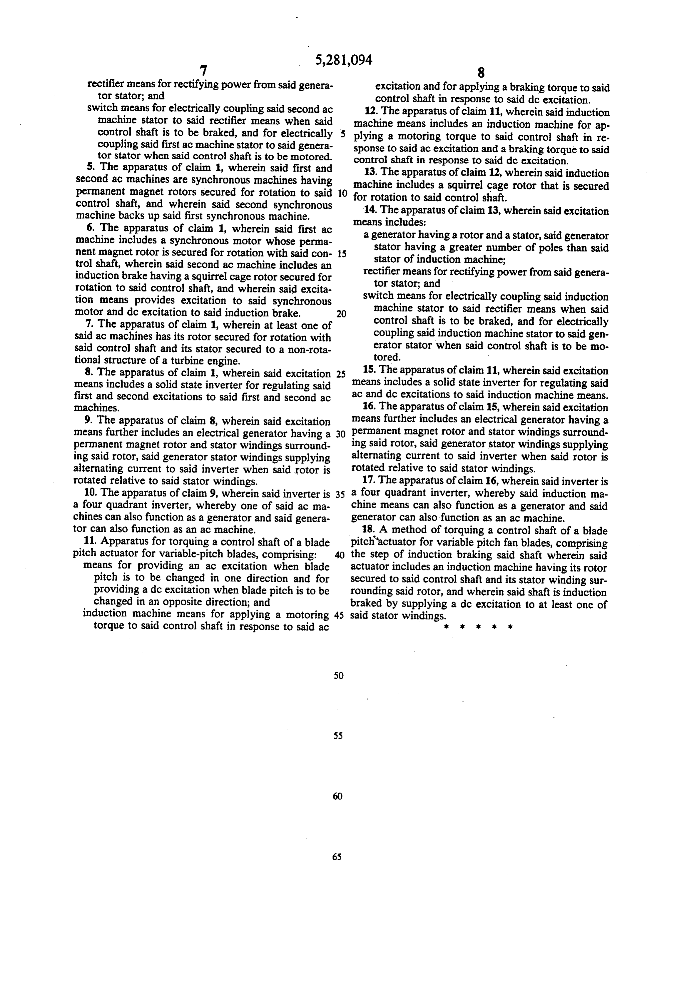
rectifier means for rectifying power from said genera excitation and for applying a braking torque to said tor stator; and control shaft in response to said dc excitation. switch means for electrically coupling said second ac 12. The apparatus of claim 11, wherein said induction machine stator to said rectifier means when said control shaft is to be braked, and for electrically plying a means machine includes an induction machine for ap motoring torque to said control shaft in re coupling said first ac machine stator to said genera sponse to said ac excitation and a braking torque to said tor stator when said control shaft is to be motored.
5. The apparatus of claim 1, wherein said first and control 13. The shaft in response to said dc excitation.
apparatus of claim 12, wherein said induction second ac machines are synchronous machines having machine includes a squirrel cage rotor that is secured permanent magnet rotors secured for rotation to said 10 control shaft, and wherein said second synchronous for14.rotation to said control shaft. The apparatus of claim 13, wherein said excitation machine backs up said first synchronous machine. means includes:
6. The apparatus of claim 1, wherein said first ac a generator having a rotor and a stator, said generator machine includes a synchronous motor whose perma stator having a greater number of poles than said ment magnet rotor is secured for rotation with said con 15 stator of induction machine; trol shaft, wherein said second ac machine includes an induction brake having a squirrel cage rotor secured for rectifier means for rectifying power from said genera rotation to said control shaft, and wherein said excita tor stator; and tion means provides excitation to said synchronous switch means for electrically coupling said induction motor and dc excitation to said induction brake. 20 machine stator to said rectifier means when said 7. The apparatus of claim 1, wherein at least one of control shaft is to be braked, and for electrically said ac machines has its rotor secured for rotation with coupling said induction machine stator to said gen said control shaft and its stator secured to a non-rota erator stator when said control shaft is to be mo tional structure of a turbine engine. tored.
8. The apparatus of claim 1, wherein said excitation 25 15. The apparatus of claim 11, wherein said excitation means includes a solid state inverter for regulating said means includes a solid state inverter for regulating said first and second excitations to said first and second ac ac and dc excitations to said induction machine means. machines. 16. The apparatus of claim 15, wherein said excitation 9. The apparatus of claim 8, wherein said excitation means further includes an electrical generator having a means further includes an electrical generator having a 30 permanent magnet rotor and stator windings surround permanent magnet rotor and stator windings surround ing said rotor, said generator stator windings supplying ing said rotor, said generator stator windings supplying alternating current to said inverter when said rotor is alternating current to said inverter when said rotor is rotated relative to said stator windings. rotated relative to said stator windings. 17. The apparatus of claim 16, wherein said inverter is 10. The apparatus of claim 9, wherein said inverter is 35 a four quadrant inverter, whereby said induction ma a four quadrant inverter, whereby one of said ac ma chine means can also function as a generator and said chines can also function as a generator and said genera generator can also function as an ac machine. tor can also function as an ac machine. 18. A method of torquing a control shaft of a blade 11. Apparatus for torquing a control shaft of a blade pitch actuator for variable pitch fan blades, comprising pitch actuator for variable-pitch blades, comprising: the step of induction braking said shaft wherein said means for providing an ac excitation when blade actuator includes an induction machine having its rotor pitch is to be changed in one direction and for secured to said control shaft and its stator winding sur providing a dc excitation when blade pitch is to be rounding said rotor, and wherein said shaft is induction changed in an opposite direction; and braked by supplying a dc excitation to at least one of induction machine means for applying a motoring 45 said stator windings.
torque to said control shaft in response to said ac k s k k r
Provenance
- Collection
- Cited prior art
- Original PDF
- patentimages.storage.googleapis.com →
- Filed
- 1992-09-22
- Pages
- 9
- Method
- pdftotext (the PDF's own text layer) + pdftoppm 300dpi page scans
- Source
- Google Patents bibliographic record
- Granted
- 1994-01-25
- Inventors
- Frederick B. McCarty; Leroy A. Fizer; Daniel E. Wilson; Kenneth L. Wuertz; AlliedSignal Inc
- Transcribed from
- patentimages.storage.googleapis.com →