patent · US4354126
Dynamoelectric machine with a permanent magnet rotor having laminated poles
12 October 1982
Page 1 — bibliographic record
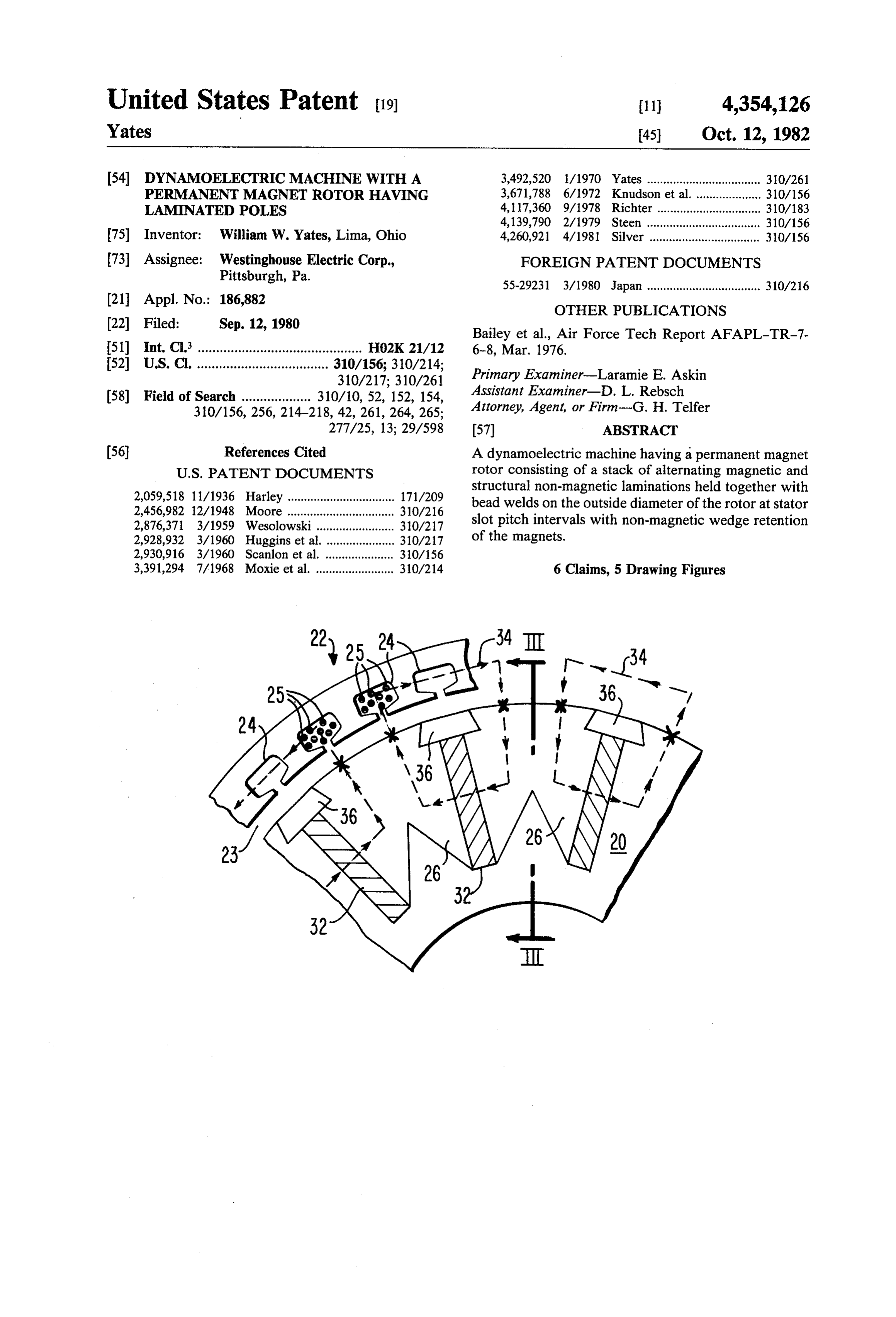
United States Patent (19) 11 4,354,126 Yates 45) Oct. 12, 1982 54 DYNAMOELECTRIC MACHINE WITH A 3,492,520 1/1970 Yates ................................... 30/26 PERMANENT MAGNET ROTOR HAVING 3,671,788 6/1972 Knudson et al. . ... 310/156 LAMINATED POLES 4,117,360 9/1978 Richter ......... ... 310/183 4,139,790 2/1979 Steen ... ... 310/156 75) Inventor: William W. Yates, Lima, Ohio 4,260,921 4/1981 Silver .................................. 310/156 (73) Assignee: Westinghouse Electric Corp., FOREIGN PATENT DOCUMENTS Pittsburgh, Pa. 55-29231 3/1980 Japan ................................... 310/216 21 Appl. No.: 186,882 OTHER PUBLICATIONS
Bailey et al., Air Force Tech Report AFAPL-TR-7- 51) Int. Cl. ............................................. H02K 21/12 6-8, Mar. 1976.
52) U.S. C. .................................... 310/156; 310/214; Primary Examiner-Laramie E. Askin
(58) Field of Search ................... 310/10, 52, 152, 154, Attorney, Agent, or Firm-G. H. Telfer
277/25, 13; 29/598 (57) ABSTRACT (56) References Cited A dynamoelectric machine having a permanent magnet
2,059,518 11/1936 Harley ................................. 171/209 structural non-magnetic laminations held together with bead welds on the outside diameter of the rotor at stator 2,456,982 12/1948 Moore..... ... 310/216 2,876,371 3/1959 Wesolowski .... ... 310/217 slot pitch intervals with non-magnetic wedge retention 2,928,932 3/1960 Huggins et al. ..... . 310/217 of the magnets.
2,930,916 3/1960 Scanlon et al. ..... ... 310/156 3,391,294 7/1968 Moxie et al. ........................ 310/214 6 Claims, 5 Drawing Figures
Page 2
Drawing sheet — no readable text.
Page 3
Drawing sheet — no readable text.
Page 4
DYNAMOELECTRIC MACHINE WITH A
from the stator slot openings which cause a high fre
PERMANENT MAGNET ROTOR HAVING
quency variation in the magnetic flux on the surface of
LAMINATED POELES
the magnet as it rotates resulting in high eddy current losses.
BACKGROUND AND SUMMARY OF THE
To obtain a higher strength structure, the preceding
INVENTION described rotor can be modified to contain the magnets inside a high strength enclosure. Such an enclosure
This invention relates to dynamoelectric machines, normally requires ferrous material radially above the and methods of their construction, that include prema 10 magnets to conduct the flux to the air gap and non-fer nent magnets assembled with laminated pole members. rous material between the magnets to avoid magneti Available permanent magnets, such as rare earth cally shorting them. This type of structure still does not magnets, have made it attractive to construct dynamo use rare earth magnets effectively, has high eddy cur electric machine rotors with permanent magnets rather rent losses in the solid enclosure and, also, is difficult to than wound coils for providing field excitation. Key manufacture because it requires weldments between advantages of the permanent magnet rotors are reduc 15 ferrous and non-ferrous materials. tions in weight and size which are particularly impor A form of high strength enclosure construction tant in applications such as aircraft. which attempts to address some of these problems is Aircraft generators have traditionally been AC syn shown in FIG. 1. It is described in Technical Report chronous machines usually with a brushless excitation AFAPL-TR-76-8, March 1976, “150 KVA Samarium system on the rotor involving a rotating rectifier con 20 struction with a field winding fed by a separate exciter Cobalt
Phase 1
USCF Starter Generator Electrical System, , " by General Electric Company, Aircraft generator. Constructing the rotor of permanent mag Equipment Div., Binghamton, New York, for Air nets eliminates the exciter generator, the field winding, Force Aeropropulsion Laboratory, Air Force Wright and related rotating rectifier. This need for a small aux Aeronautical Laboratories, iliary permanent magnet generator to supply start-up 25 mand, Wright Patterson AirAir Force Systems Com Force Base, Ohio 45433.
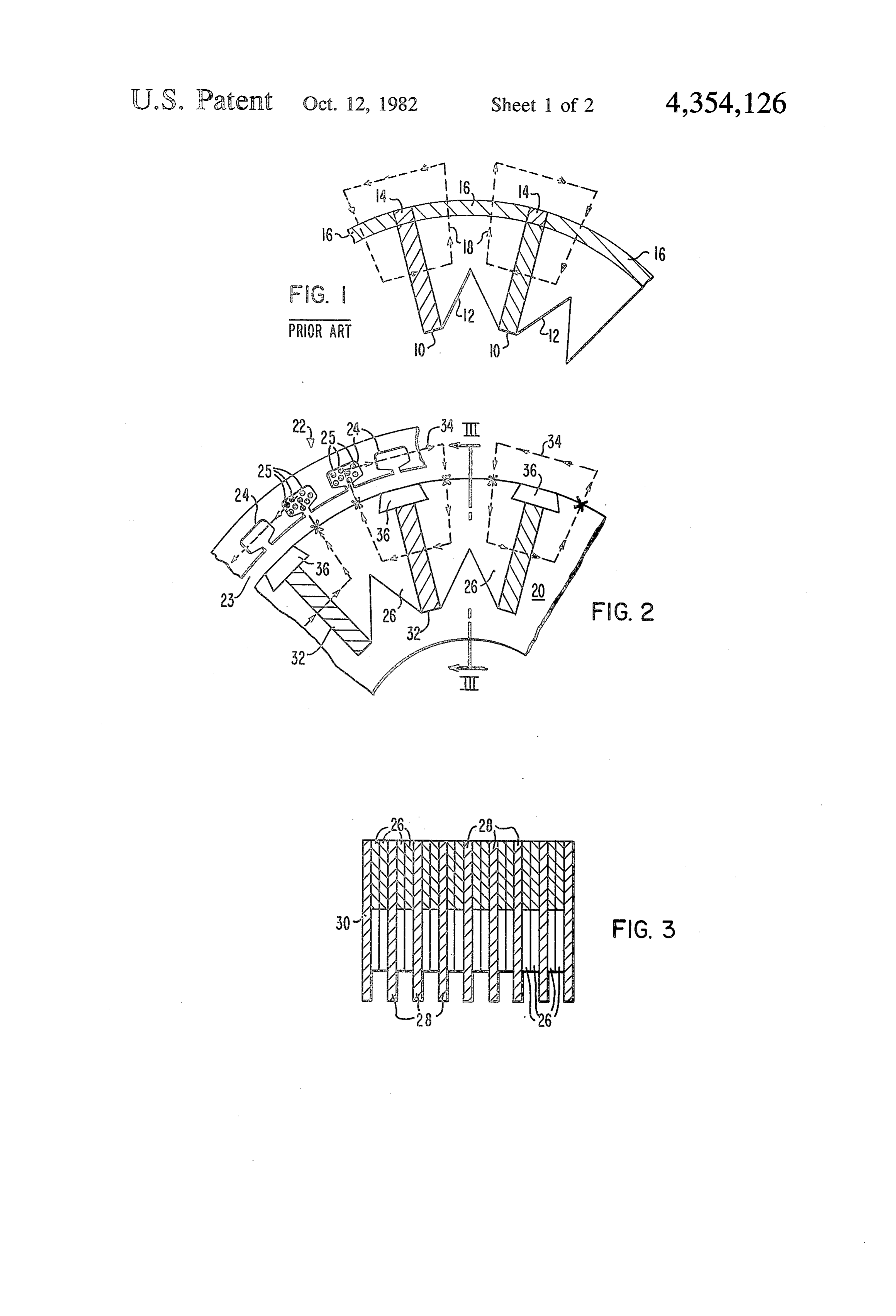
power is also eliminated. Aircraft generators are nor Here, elongated, rectangular cross-section, magnets 10 mally driven at a constant speed by means of a hydrau are disposed to run in radial planes through the rotor lic speed conversion system operating off of a variable speed engine. Now it has become desirable to operate core. The intervening core material is of magnetic steel aircraft generators at a variable speed, eliminating the 30 laminations or lamination segments 12. The periphery hydraulic speed conversion system, and to develop a of the rotor comprises non-ferrous metal strips 14 run constant frequency electrical output by electronic ning over the face of the permanent magnets. The strips power conversion systems such as a cycloconverter 14 are welded together with partial cylindrical ferrous system. Such a power conversion system can also per steel members 16 over the pole region. The generated mit operation of the generator in a reverse mode to 35 magnetic flux paths 18 result from an orientation of the obtain motor operation useful for starter-generator sys magnetic axis of the magnets circumferentially in the tems on aircraft engines or flywheel energy storage and rotor. Thus, the flux path is out of one side of a magnet retrieval. A brushless wound field machine is not as 10 into the ferrous pole piece adjacent to it and then attractive for this purpose because it requires an exciter turns radially into the machine air gap. The flux returns generator whose size has to be increased for capability from the air gap through an adjacent pole down into the of operating at decreased speed. other side of the magnet. Because the area of the magnet Another area of interest for application of machines can be extended radially, the flux from one magnet can with permanent magnet rotors is in brushless DC mo be compressed into a relatively small area of the ferrous tors. These offer advantages in efficiency and in size and material in the pole at the air gap. This utilizes the mag weight as opposed to wound rotors. The opportunity is 45 net material much more effectively than the structure available to obtain low rotor inertia, using rare earth previously referred to. However, the disadvantages of magnets, in actuators for control surfaces in aircraft or high eddy current losses and difficulty of manufacture other applications where quick response is required. remain.
Electric rather than hydraulic actuators are therefore Various aspects of permanent magnet rotor construc made possible and provide an opportunity for totally 50 tion in accordance with the prior art, including some electric aircraft systems. features as discussed above as well as others, and vari One construction for a permanent magnet rotor con ous aspects of permanent magnet rotor application are sists of the magnets having their magnetic axes radially described in the following representative patents: Har disposed with the magnet surface exposed to the ma ley U.S. Pat. No. 2,059,518, Nov. 3, 1936; Yates U.S. chine air gap. The magnets are anchored, such as by an 55 Pat. No. 3,492,520, Jan. 27, 1970; Knudson et al. U.S. adhesive bonding material, to an underlying ferrous Pat. No. 3,671,788, June 20, 1972; Richter U.S. Pat. No. member which conducts magnetic flux from pole to 4,117,360, Sept. 26, 1978; and Steen U.S. Pat. No. pole. While this is a relatively simple construction, it is 4,139,790, Feb. 13, 1979.
not suitable for high speed operation because of the The present invention achieves the multiple objec weak structure of the magnets themselves and the joints 60 tives of providing a permanent magnet rotor in a high at which they are bonded to the ferrous member. An strength construction, with low eddy current losses, other disadvantage, when rare earth magnets are used, effective utilization of permanent magnets, and com is the low flux density in the air gap resulting from the plete containment of the magnets in an economically normal characteristics of rare earth magnets which manufactured structure. Briefly, the rotor structure have a relatively low flux density-high coercive force 65 comprises a core of a plurality of stacked laminations characteristic. Therefore, this type of construction does that include predominantly magnetic laminations that not use the magnets effectively. Another disadvantage, have interspersed among them non-magnetic lamina with magnets that are electrically conductive, results tions for structural strength. The magnets are located in
Page 5
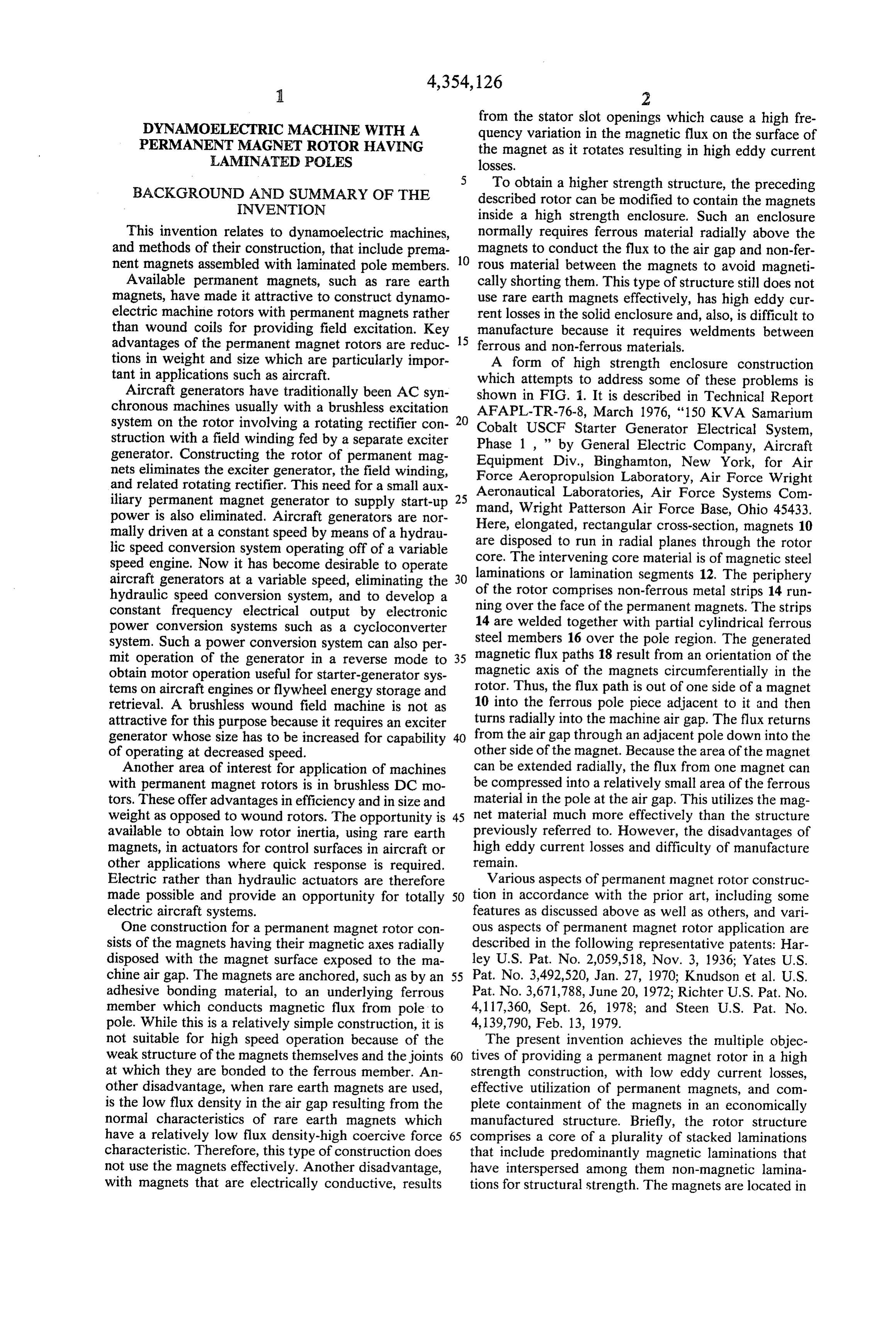
radial planes running longitudinally through the core Referring again to FIG. 2, permanent magnets 32 are and have a circumferential magnetic field orientation located on radial planes extending longitudinally for effective magnet usage. The magnets are secured by through the core (in slots 31A of laminations 28) with a wedges extending longitudinally through the core at the circumferential magnetic axis so as to produce the indi outer periphery with the wedges being of non-magnetic cated flux paths 34. The permanent magnets 32 may be material that is mechanically locked in place within of rare earth type or other permanent magnet material. laminations while the outer edges of the laminations The laminations are secured together by bead welds between wedges form pole members and are exposed to extending longitudinally on the core periphery (indi the air gap. A plurality of bead welds extend longitudi cated by the small x's on FIG. 2), preferably in a depres nally over the surface of the core to secure the lamina O sion thereof so as not to extend into the air gap 23. tions into a unit while minimizing the surface area of the These bead welds are preferably spaced the same dis core that is shielded from the air gap. In a preferred tance as the stator slots 24 for lower induced voltages. form of the invention, the bead welds securing the rotor The permanent magnets 32 are disposed within the laminations are coordinated with the stator slot pattern 15 slots 31A in the laminated structure with non-ferrous metal or organic wedges 36 driven in place, in the upper such that they are spaced from each other by a distance ends of slots 31A as well as the slots 31B in the end equivalent to the stator slot pitch to minimize current laminations 30, to lock them in without requiring any flow from induced voltages in the welds. welds between the wedges 36 and the adjacent lamina In accordance with the method of assembly of this invention, a stack of laminations is assembled on an 20 tion material. The intervening poles are exposed to the arbor using slots on the outside diameter of the high air gap 23 so as to utilize the magnetic field more effec strength lamination with wedge-shaped locating fix tively. The number of magnetic laminations 26 to non-mag tures that extend into the slots to locate and hold the magnetic laminations preparatory to welding. The bead netic vantage laminations 28 is not critical. The apparent disad of this structure in using part of the area nor welds are then applied to run across the length of the 25 mally used for magnetic steel for non-magnetic struc stack. The permanent magnets are then inserted in the tural steel, which slots in the stack, after welding the laminations, so as to ing in the need forwould tend to saturate the steel result avoid any necessary machining operation of the lamina use of lower effectivemore exotic magnetic steels or the tions with a magnetized magnet in place. Then nonfer to wound field mechanics, densities, air gap is, in comparison not a disadvantage. The rous metal or high strength non-metallic wedges are 30 magnetic sections that limit magnetic flux on a wound inserted into the outer ends of the slots to retain the field machine are usually much thinner than the polar magnets without requiring welding operations. Me surface on the rotor that is exposed to the air gap. Thus, chanical strength is further improved by dipping the for equivalent air gap densities in this structure, a nor assembly in a varnish dip and then drying it. mal steel can be used to preserve the intended economy BRIEF DESCRIPTION OF THE DRAWINGS 35 of the structure.
In assembly, an arbor or fixture is used on which to
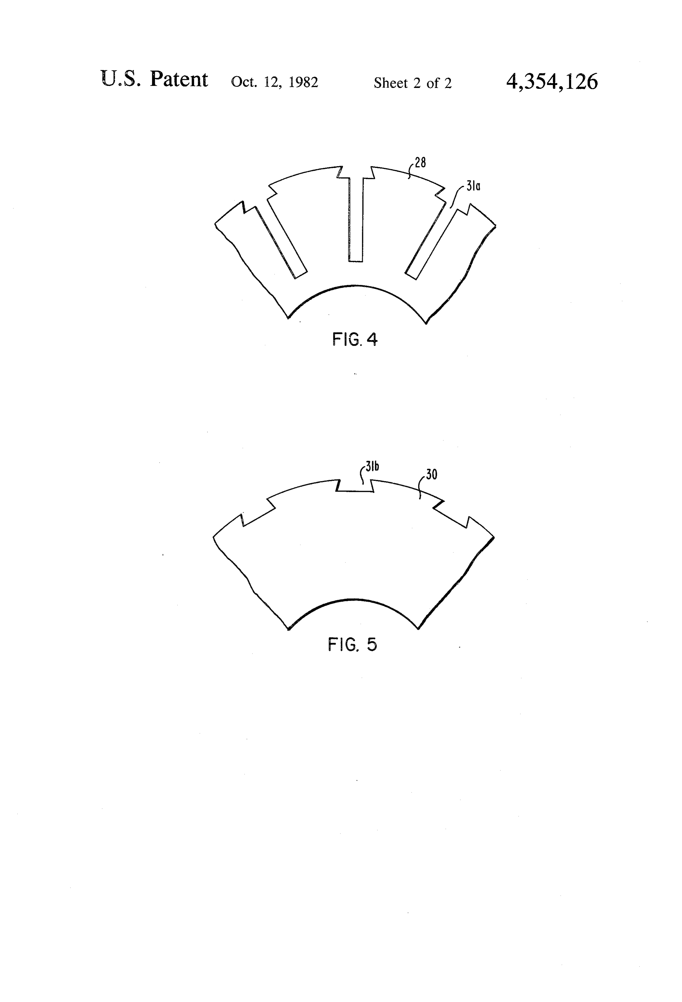
FIG. 1 is a partial cross-sectional view of a permanent stack the laminations 26, 28 and 30 using the slot pattern magnet rotor in accordance with one embodiment of on the outside diameter of the high strength laminations the prior art, as is discussed above; with wedge-shaped locating fixtures shaped in the form FIG. 2 is a partial cross-sectional view of a dynamo 40 of the ultimately used wedges but with extensions into electric machine in accordance with an embodiment of the slots to locate and hold the magnetic laminations the present invention; preparatory to welding. After the non-magnetic and FIG. 3 is a partial longitudinal cross-section of a magnetic laminations, or lamination segments of the dynamoelectric machine rotor generally in accordance latter, have been stacked together, the structure is with a view along line III-III of FIG. 2; and, 45 welded. Weld beads using TIG or other appropriate FIGS. 4 and 5 are plan views of lamination elements methods are run across the length of the stack at least of the rotor of FIGS. 1 and 2. one per pole. The magnetic and non-magnetic material DESCRIPTION OF THE PREFERRED should be selected to be materials such as Hipernik EMBODIMENTS (50% nickel/steel alloy) and Inconel alloy, respectively, 50 in order to obtain a satisfactory weld. Sufficient weld
Referring to FIG. 2 of the drawings, a dynamoelec depth without raised material can be obtained by tric machine is shown with a permanent magnet rotor punching a depression in each lamination for the weld 20 in inductive relation with a normal stator 22 contain or by welding after grinding the outside diameter to an ing slots 24 and coil windings 25, with air gap 23 there appropriate configuration size. Bead welds are provided between. The rotor 20 comprises a lamination structure 55 at a spacing that is equal to the stator slot pitch so all including ferrous laminations 26 that are in stacked voltages induced in the welds are in phase and currents relation with non-ferrous structural laminations. As do not flow. It is desirable that the width of the welds be shown in FIG. 3, non-magnetic structural laminations held to a minimum to minimize local eddy currents in 28 are interspersed in the core structure after about the welds caused by perturbation in the airgap flux from every two magnetic laminations 26. There are also pro 60 the stator slot openings.
vided non-magnetic end laminations 30. The magnetic Premagnetized magnets 32 can be inserted in the slots laminations 26 are preferably lamination segments as in the stack at the last possible manufacturing stage to shown in FIG. 2. The non-magnetic structural lamina avoid machining with a magnetized magnet in place. tions 28 are continuous arcuate members having slots Non-ferrous metal or high strength non-metallic 31A for magnet and wedge location as shown in FIG. 4. 65 wedges 36 shaped as shown in FIG. 2 are then inserted The end laminations 30, as shown in FIG. 5, include into the outer slots to retain the magnets. These opera tapered shallow slots 31B for wedges for securing the tions can be followed by a subsequent varnish dip and elements together. bake to avoid movement of the magnets. For high speed
Page 6
S 6 operation, where the varnish may not give sufficient a plurality of bead welds extending longitudinally mechanical retention to prevent magnet motion, it must over the surface of said core to secure said lamina be assured that the magnet is situated against the wedge tions into a unit while minimizing the surface area either by forcing it there during assembly or providing of said core that is shielded from the air gap. spacers under the wedge. 5 2. A dynamoelectric machine in accordance with The invention has been successfully demonstrated in claim 1 wherein:
a permanent magnet generator rotor of a diameter of 3.0 said non-magnetic structural laminations through in. that was run on test equipment at speeds up to a which said permanent magnets extend are each a maximum of 36,000 rpm. Structural failure only oc circular element having slots for accommodating curred at the maximum speed where the wedges were 10 said magnets and for accommodating and locking of non-metallic material. With aluminum wedges, no said wedges; and adverse effects were found even at the maximum test said magnetic laminations comprise, in each lamina speed. The tests demonstrated the suitability of the tion plane, a plurality of lamination segments con design for aircraft engine drives designed for a maxi figured to fit between adjacent magnet and wedge mum speed of 26,250 rpm. 15 locations.
Thus, there has been described an improved perma 3. A dynamoelectric machine in accordance with nent magnet rotor, and method of making it, that claim 2 wherein:
achieves the objectives of high strength, while utilizing said rotor core also includes an end lamination of magnets effectively in an easily manufactured structure. non-magnetic material at each end of said stack It will be apparent that certain variations and modifica 20 that has notches for receiving said wedges, and said tions may be made from the specific embodiment as magnets abut against said end laminations; and shown within the general teachings of this invention. said rotor bead welds secure said end laminations I claim: with said other laminations. 1. A dynamoelectric machine comprising: 4. A dynamoelectric machine in accordance with a stator and a rotor in a mutually inductive rotation 25 claim 3 wherein:
with an air gap therebetween; said rotor bead welds are the sole metallurgical bond said rotor comprising a core of a plurality of stacked securing said core, including said laminations, said laminations including magnetic laminations and magnets and said wedges into a unit. non-magnetic structural laminations interspersed 5. A dynamoelectric machine in accordance with among said non-magnetic laminations as one pro 30 claim 1 wherein:
ceeds longitudinally through said core; said stator comprises a magnetic core with a plurality said rotor core having a plurality of permanent mag of longitudinally running coil slots within the inner nets extending therethrough producing a plurality surface thereof and a coil winding disposed in said of magnetic flux paths circumferentially disposed slots; and about the periphery of said core, said plurality of 35 said rotor bead welds are spaced from each other by permanent magnets each having a rectangular a distance equivalent to the stator slot pitch to cross-section and each having major surfaces ori minimize current flow from voltages induced in ented in a substantially radial plane; said welds.
each of said permanent magnets being secured against 6. A dynamoelectric machine in accordance with radially outward movement by a wedge extending 40 claim 5 wherein:
longitudinally through said core at the outer pe said plurality of laminations of said rotor core have riphery thereof, said wedges being of non-magnetic on their outer surface longitudinally running de material and mechanically locked in place within pressions in which said bead welds are disposed to said laminations while said radially outer edges of avoid raised materialk insk thesk airk gap. said laminations between wedges are exposed; 45
Provenance
- Collection
- Cited prior art
- Original PDF
- patentimages.storage.googleapis.com →
- Filed
- 1980-09-12
- Pages
- 6
- Method
- pdftotext (the PDF's own text layer) + pdftoppm 300dpi page scans
- Source
- Google Patents bibliographic record
- Granted
- 1982-10-12
- Inventors
- William W. Yates; Westinghouse Electric Corp
- Transcribed from
- patentimages.storage.googleapis.com →