patent · US3004782
Shaft seal
17 October 1961
Page 1
Drawing sheet — no readable text.
Page 2
United States Patent Office1
Patented Oct. 17, 1961
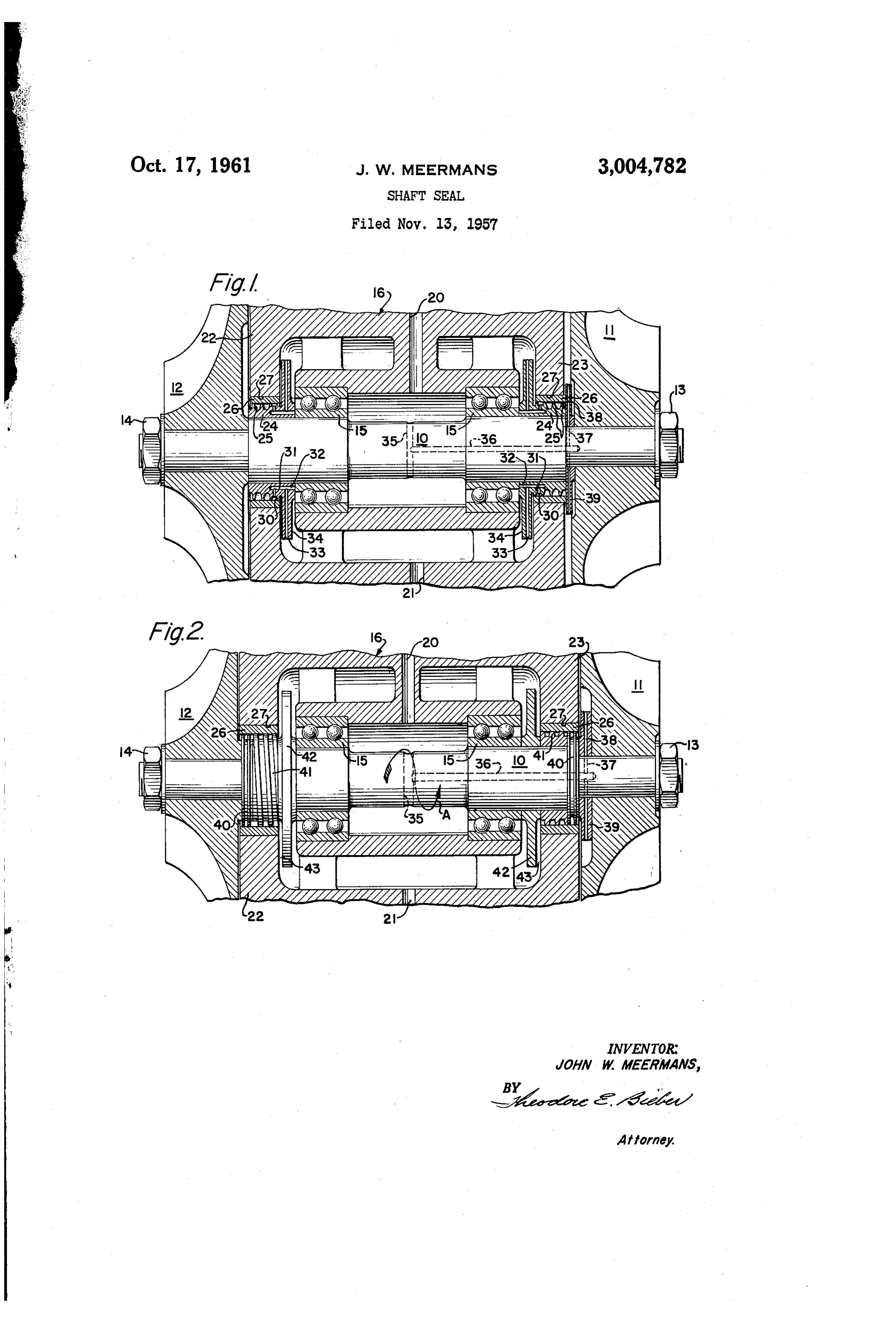
a shaft seal constructed according to this invention; and 1, 3,004,782 FIG. 2 is a modification of the shaft seal shown in 8. SHAFT SEAL FIG. 1 which utilizes a screw type of pump in place of John William Meermans, North Hollywood, Calif., as the centrifugal pump shown in FIG. 1. . signor to The Garrett Corporation, Los Angeles, Calif., 5 Referring to FIG. 1, there is shown a turbine-driven a corporation of California compressor unit having a shaft 10 with a turbine wheel Filed Nov. 13, 1957, Ser. No. 696,142 11 mounted on one end and a compressor wheel 12
mounted on the opposite end. The turbine and com
This invention pertains to shaft seals and more par pressor wheels are secured to opposite ends of the shaft ticularly to a shaft seal which incorporates a means for O by means of nuts 13 and 14. The shaft 10 is rotatably positively scavenging the oil from the seal and returning supported in the housing 16 of the unit by means of it to the interior of the housing in which the shaft is two spaced ball bearings 15. A passageway 20 is formed mounted. in the housing 16 for supplying lubricant to the two In many rotating machines it is necessary to provide bearings 15, while a drain line 21 is formed on the shaft seals where the rotating shaft projects through an 5 bottom of the housing for removing the lubricant. opening in the bearing housing, in order to prevent the The shaft sealing means of this invention is disposed escape of lubricant from the housing. All shaft seals, on the portion of the shaft 10 which projects through of course, have a rotating part and a stationary part, the opposite end walls 22 and 23 of the housing. The and some lubricant will flow along the static surface of shaft sealing means consists of a sleeve member 24, the stationary part and escape from the bearing housing 20 which is secured to the shaft 10 and a stationary bush regardless of the effectiveness of the shaft seal. The ing 26 mounted, as by pressing, in the bores 27 of the quantity of oil lost by escaping along the static member end walls. The sleeve member 24 is provided with a is usually very small but in machines which must oper radial flange 34 at its inboard end and a plurality of ate with an absolute minimum of oil consumption even radially projecting lands or ridges 25 adjacent its out this small loss cannot be tolerated. For example, in 25 board end. The bushing 26 is preferably formed of a turbine-driven compressors used on air cycle air con softer material than the sleeve 24 so that any actual ditioning systems in aircraft, the quantity of lubricant contact between the lands or ridges 25 and the bush carried by the machine is small and losses must be held ing will result in wearing away of the bushing and not to a minimum if the machine is to operate for long the lands. The outer diameter of the lands 25 should periods without maintenance or servicing. 30 be made substantially the same as the inner diameter of This invention solves the problem of lubricant escap the bushing 26 and assembled by broaching the sleeve ing from the bearing housing along the static portion 24 into the bushing 26. This will insure that the lands of the seal by providing a shaft seal utilizing a labyrinth in cooperation with the bushing will form an effective or other type seal on the outboard end of the shaft and 35 labyrinth type seal.
a positive pump means for removing oil from the in A shallow circumferential groove 30 is formed in board end of the shaft seal and returning it to the the outer surface of the sleeve. 24 immediately adjacent interior of the housing. The pump means is disposed the inboard end of the innermost one of the lands 25. so that its suction inlet opens adjacent the inboard end The outer surface of the sleeve 24 on which the groove of the labyrinth seal and its discharge outlet communi 40 30 is formed should have substantially the same diameter cates with the interior of the housing. The use of the as the outer diameter of the lands 25, as shown in FIG. 1. pump creates sufficient force to remove the lubricant - A plurality of spaced radial passageways 31 are formed from the static part of the seal and return it to the in the sleeve 24 and connect with the shallow groove 30 bearing housing. - - and a plurality of axial passageways 32 also formed in Accordingly, it is the principal object of this inven 45 the sleeve 24. The axial passageways 32, in turn, con tion to provide a shaft seal utilizing a low leakage type nect with a plurality of spaced radial passageways 33 seal and a pump means to scavenge the oil from the which are formed in the radial flange 34. inboard end of the seal and return it to the interior of The interior of the housing 16 is vented to the turbine the housing. end of the unit by means of drilled passageways 35 and Another object of this invention is to provide a shaft 36 in the shaft 10. The right end of the passageway 36 seal which utilizes a labyrinth type seal on the outboard 50 connects by means of drilled holes 37 with the inlet end of the shaft and a centrifugal pump mounted ad ends of the impeller passages 38 in the impeller 39. jacent the inboard end of the labyrinth seal. The Suction The impeller will create a sufficient pressure differential inlet of the centrifugal pump is connected to a shallow to properly vent the housing 16 to the turbine end of circumferential groove formed in the outer surface of the unit as is more fully explained and claimed in a the shaft seal immediately adjacent the inboard end of 55. co-pending application of R. L. Schinnerer entitled the labyrinth seal, while the pump discharges into the “Lubrication System For High Speed Machines,” Serial interior of the housing. : No. 535,643, filed September 21, 1955. A further object of this invention is to provide a When the turbine-compressor unit described above shaft seal utilizing a labyrinth seal on the outboard end 60 is operated, lubricant will tend to escape not only along of the shaft and a screw type positive displacement pump the shaft 10 where it projects through the end walls 22 to remove oil from the inner surface of the stationary and 23 but also along the inner or static Surface of member of the labyrinth seal and return it to the in bushing 26. The leakage of lubricant from the interior terior of the housing. of the housing 16 will be controlled by the labyrinth Seal These and other objects and advantages of this in 65 at the outboard end of the shaft and the scavenging ac vention will be more easily understood by those skilled tion of the pump. In order to remove the lubricant from in this art from the following detailed description of the static surface of the bushing 26, the shallow groove the preferred embodiment thereof, and from a modifi 30 and the suction of the centrifugal pump which is cation of this embodiment, when taken in conjunction formed in the flange 34 by the radial passageways 33 with the attached drawing, in which: are utilized. This suction pressure in the passageways FIG. 1 is a longitudinal cross-section of a rotating 0. face 31 will tend to draw the lubricant from the inner Sur of the bushing 26 so that it may be returned to assembly of a turbine-driven compressor unit showing
Page 3
the interior of the housing 16 by the pumping action formed in the outer surface of said sleeve portion ad of the radial passageways 33. The groove 30 should jacent the inboard end of said bushing; and centrifugal be maintained relatively shallow so that a sufficient suc pumping means actuated by the rotation of said shaft tion will be created in close proximity to the inner sur and operatively connected to the circumferential groove face of the bushing 26 to remove any lubricant from this in said sleeve portion for creating a suction in the groove surface. This is necessary in order to eliminate the to Scavenge fluid from the surface of said bushing abut effects of the centrifugal force set up in the groove 30. ting said groove and discharging it into the interior of A modification of the invention is shown in FIG. 2 said housing.
in which helical lands 41 are formed on the inboard 3. A fluid seal for a shaft rotatably mounted in a ends of the shaft where it projects through the end walls 0 bore in a housing, comprising: a bushing fixedly mounted 22 and 23. Of course, the helical lands must have op in the bore; sealing means disposed within said bushing, positely directed pitches in order that they will both the sealing means including a member mounted on the tend to pump to the center of the housing when the shaft and provided with a labyrinth type seal having shaft rotates in one direction. The outer diameter of projecting land means in close fit with said bushing, said the land 41 should be substantially the same as the bore 5 member having a sleeve portion in close fit with said of the bushing 26 in order to provide a good pumping bushing, the sleeve portion having a circumferential action. A labyrinth seal 40 similar to the labyrinth seal groove in the surface contiguous said bushing adjacent shown in FIG. 1 is provided on the outboard end of the the inboard end thereof; and pumping means formed on shaft. A radial flange 42 is also provided on the in the inboard end of said member for creating a suction in board end of the shaft and operates as a slinger to trans 20 said groove to scavenge fluid from the surface of said fer the oil from the end of the helical land 41 back to bushing abutting said groove and returning it to the the interior of the housing 16. interior of the housing.
When the unit shown in FIG. 2 is rotated in the di 4. A fluid seal for a shaft rotatably mounted in a bore rection shown by the arrow A, the helical lands 41 will 25 in a housing, comprising: a bushing fixedly mounted in act as screw pumps to remove the lubricant which flows the bore; sealing means disposed within said bushing, along the inner surface of bushing 26 and cause it to ...the sealing means including a member mounted on the flow towards the radial flanges 42. The lands 41 in shaft and provided with a labyrinth type seal having pro addition to their pumping action will tend to scrape the jecting land means in close fit with said bushing, said lubricant from the inner surface of the bushing 26 and member having a sleeve portion in close fit with said cause it to flow towards the slingers due to the close 30 bushing, the sleeve portion having a circumferential clearances between the land 41 and the bushing 26. groove in the surface contiguous said bushing at a region While but two specific embodiments of this invention intermediate the land means and the inboard end of said have been described in detail, many modifications and bushing; and pumping means formed on the inboard end changes will occur to those skilled in the art within its 35. of said member for creating a suction in said groove to broad spirit and scope. scavenge fluid from the surface of said bushing abutting I claim: said groove and returning it to the interior of the housing. 1. A fluid seal for a shaft rotatably mounted in a bore 5. A fluid seal for a rotary shaft disposed through an in a housing, comprising: a bushing fixedly mounted in opening in a wall of a housing, comprising: sealing means said bore; sealing means mounted on said shaft, the 40 disposed within the opening, the sealing means includ sealing means including a labyrinth portion having a ing a member mounted on the shaft and provided with plurality of radially projecting lands in close fit with a labyrinth type seal having projecting land means in said bushing and a sleeve portion in close fit with the close fit with the wall of the opening, said member having bushing inboard of said lands; a circumferential groove a sleeve portion in close fit with the wall of the opening, formed in the outer surface of said sleeve portion ad 45 the sleeve portion having a circumferential groove in the jacent the inboard end of said bushing; pumping means surface contiguous the wall of the opening and adjacent comprising a radially projecting flange formed on the the inboard end thereof; and pumping means formed on sealing means and a plurality of radially extending ejec the inboard end of said member for creating a suction tion passages in said flange adapted to discharge into in said groove to scavenge fluid from the surface of the interior of said housing; and passage means con 50 the wall of the opening abutting said groove and return necting said circumferential groove with the pumping ing it to the interior of the housing.
means for creating a suction in said groove to scavenge fluid from the surface of the bushing abutting said References Cited in the file of this patent groove. UNITED STATES PATENTS 2. A fluid seal for a shaft rotatably mounted in a 55 1,313,736 Rice ----------ress an a Aug. 19, 1919 bore in a housing, comprising: a bushing fixedly mounted 1908,956 Chievitz---------------- May 16, 1933 in said bore; sealing means mounted on said shaft, the 2,245,281 Klopak ---------------- June 10, 1941 sealing means, including a labyrinth portion having a 2,274,836 Koster ----------------- Mar. 3, 1942 plurality of radially projecting lands in close fit with 2,383,531 Caruthers -------------- Aug. 28, 1945 said bushing and a sleeve portion in close fit with the 60 2,524,124 Gyana ------------------ Oct. 3, 1950 bushing inboard of said lands; a circumferential groove
Provenance
- Collection
- Cited prior art
- Original PDF
- patentimages.storage.googleapis.com →
- Filed
- 1957-11-13
- Pages
- 3
- Method
- pdftotext (the PDF's own text layer) + pdftoppm 300dpi page scans
- Source
- Google Patents bibliographic record
- Granted
- 1961-10-17
- Inventors
- Meermans John William; Garrett Corp
- Transcribed from
- patentimages.storage.googleapis.com →