patent · US5844341A
Electromagnetic machine with at least one pair of concentric rings having modularized magnets and yokes
1 December 1998
Page 1 — bibliographic record
United States Patent (19) 11 Patent Number: 5,844,341 Spooner et al. (45) Date of Patent: Dec. 1, 1998 54 ELECTROMAGNETIC MACHINE WITHAT 4,291,235 9/1981 Berger et al. .. ... 290/55 LEAST ONE PAR OF CONCENTRC RINGS 4,476,395 10/1984 Cronin ........................................ 290/6 HAVING MODULARIZED MAGNETS AND 4,613,779 9/1986 Meyer ..................................... 310/112 YOKES 4.691,133 9/1987 Mongeau ................................ 310/178 4.866,321 9/1989 Blanchard et al. ..................... 310/112 75 Inventors: Edward Spooner, Durham; Alan 4,973,386 11/1990 Wust ......................................... 31.0/51 5,177.388 1/1993 Hotta et al. ............................. 310/114
Charles Williamson, Timperley, both 5,258,697 11/1993 Ford et al. .............................. 318/498 of United Kingdom
FOREIGN PATENT DOCUMENTS
73 Assignee: AEA Technology plc, Didcot, United
Kingdom 2636280 3/1990 France ................................... 310/112
21 Appl. No.: 826,634 Primary Examiner Steven L. Stephan 22 Filed: Apr. 2, 1997 ASSistant Examiner Elvin G. Enad
Attorney, Agent, or Firm-D. Peter Hochberg; William H.
Related U.S. Application Data Holt; William R. Hinds 63 Continuation of Ser. No. 247,258, May 23, 1994, aban 57 ABSTRACT doned.
An electromagnetic machine which is Suitable for use as a 30 Foreign Application Priority Data direct-drive, directly-coupled, mains electricity generator Jun. 3, 1993 GB United Kingdom ................... 931.1634 (14) to be driven by a low speed device such as a wind turbine (18), consists of one or more rotor rings (30) of many 51) Int. Cl. ............................. HO2K7/20: HO2K 17/44 permanent magnets (40) of alternating polarity, with coaxial 52 U.S. Cl. .......................... 310/112; 310/114; 310/156; Stator rings (28) of many laminated yokes (35), each yoke 310/187; 310/216 defining slots to locate coils (38). The yokes (35) and coils 58 Field of Search ..................................... 310/112, 114, (38) form modules which are supported by beams (32) 310/156, 187, 216 relative to the rotor rings (30). The rotor rings (30) may also be of modular construction. Manufacture and assembly are 56) References Cited thereby simplified, and Sub-harmonic magnetic flux compo nents are Suppressed.
2,006,172 6/1935 Klappauf ................................. 310/112 11 Claims, 2 Drawing Sheets
Page 2
Drawing sheet — no readable text.
Page 3
Drawing sheet — no readable text.
Page 4
ELECTROMAGNETIC MACHINE WITHAT pole pieces. The preferred embodiment uses rectangular LEAST ONE PAR OF CONCENTRC RINGS ferrite magnets with tapered pole pieces which project HAVING MODULARIZED MAGNETS AND beyond the Side of the magnet along one edge to define a YOKES protruding pole at the Surface of the ring. An alternative design would comprise a Steel cylinder on the Surface of
This is a continuation of application Ser. No. 08/247,258 which are mounted Several magnets, alternating in polarity filed May 23, 1994 now abandoned. around the ring and Spaced apart from each other. This invention relates to an electromagnetic machine, The rate of rotation of the rotor, and the number of primarily intended to act as a generator of electricity, but magnetic poles around a first ring, together determine the which could equally be used as an electric motor. frequency of the generated emf. For example if the rotor The machine of the invention is primarily intended as a rotates at 42.3 rp.m. and there are 142 poles (of alternating generator of mains-frequency alternating current when polarity), the generated emf will be at 50 Hz. The number of directly coupled to a device Such as a wind-energy rotor, poles must therefore be chosen in accordance with the which rotates at a much lower frequency than mains fre expected rate of rotation in order to generate an emf at a quency. It may equally be used to generate current at other 15 desired frequency.
frequencies for use with Systems where the generator feeds Where the machine is a generator the outputs from the into the mains via a frequency convertor. Hitherto it has coils may be rectified, and if the rate of rotation is variable usually been necessary to interpose a gear-mechanism this may be preferable because the rectified, dc output can between Such a rotor (which might rotate at 40 rp.m.) and then be inverted to give fixed frequency ac. Each coil may a generator of conventional type, So the generator turns be provided with a rectifier, for example a bridge rectifier, or much faster than the rotor. The use of permanent magnets to alternatively Sets of coils may be connected together in provide the magnetic field in which one or more coils are Series and the output of each Set rectified. Alternatively the moved to generate electricity is also known. For example P. coils may be interconnected to provide alternating outputs, Zielinska and K. Schoep, in an article in Proceedings of for example a three-phase output, with Several coils being International Conference on Electrical Machines, UMIST 25 asSociated with each phase. The number of poles in a ring is 1992, describe a three-phase, permanent magnet, Synchro preferably at least 24, and for a machine connected to a wind nous machine; a laminated rotor with fourteen permanent rotor there are preferably at least 100 poles. magnets arranged with alternating polarity around its perim The emfs generated in different coils will generally be of eter is rotatable within a tubular Stator with six coils locating different phases, but the coils can be connected to provide a in respective pairs of longitudinal slots along its bore. three phase output. The number of Slots is desirably kept as Diametrically opposite coils are associated with the same Small as practicable (in any one pair of rings) in order to phase, and the three phases are Said to be practically minimise the cost of coil construction and of assembly of the decoupled. machine and to allow each slot to be of Sufficient width to According to the present invention there is provided an accommodate adequate electrical insulation as well as the electromagnetic machine comprising one or more pairs of 35 coil. The number, q, of Slots per pole per phase is typically rings arranged on a common axis, in the or each pair the first between 2 and 8 in conventional machines. If Such a q value ring comprising Several permanent magnets arranged So were used in the present machine with, for example 142 there are magnetic poles alternating in polarity around the poles, then the number of slots would be at least 852 which ring at the Surface thereof facing the Second ring, and the would be impractical. Using a much Smaller value of q, of Second ring comprising Several laminated yokes, each yoke 40 say 0.3 to 0.4 (i.e. a smaller number, say 156, of slots in each defining at least one pair of slots in the Surface thereof facing ring), leads to a much lower construction cost and slots of the first ring, rectangular coils of wire locating in pairs of Satisfactory width but gives rise to Subharmonic components adjacent slots, and one of the rings being rotatable relative of magnetic flux. With a low value of q the individual coils to the other, the slots extending transverse to the direction of of the winding are physically Separated and do not overlap. relative motion of the adjacent poles. 45 This makes it possible to split the stator into a number of The first and the Second rings of each pair are preferably modules as described below. For example a first ring might concentric. The or each Second ring is modular, and can be have 142 poles, and the second ring define 156 slots in which assembled from the yokes and the associated coils in the 78 coils locate. The q value for the machine, that is the desired position relative to the first ring, which in view of the number of slots per pole per phase, is therefore 0.366. This magnetic forces between the rings is considerably easier 50 is a much Smaller q value than for conventional generators. than Sliding one complete ring inside the other, if the rings One consequence of the large number of poles in each are concentric. Preferably the first ring is a rotor, and the first ring is that the magnetic flux paths within the Second Second ring is a Stator, as it is then Simpler to make electrical ring are localised. The yokes may therefore be spaced contact with the coils. However the alternative arrangement Slightly apart by non-magnetic material without causing (with the Second ring as the rotor) may be used, if slip-ring 55 much disturbance to the flux. Hence the yokes may be of connections to the coils are acceptable. E-shape, with a flat Surface in which the slots are defined (So Preferably each yoke is of E-shaped cross-section and the Surface of the Second ring facing the magnet poles is locates a Single coil. Each yoke is desirably Supported by a actually polygonal). Such E-shaped yokes can therefore be beam extending parallel to the axis between Support mem assembled to make machines of a range of different bers at the ends of the machine. The preferred machine 60 diameters, Standardised E-shaped yokes being used in every comprises a plurality of pairs of rings arranged end to end on case. There may also be narrow gaps between adjacent pole a common axis, and each Support beam can Support one pieces in the first ring. This makes assembly of each first ring yoke from each of the Second rings; the number of Support easier, and also introduces a Significant extra reluctance into beams is thus equal to the number of yokes in a single the magnetic path for any Sub-harmonic components of Second ring. 65 magnetic flux. The pairs of first and Second rings are The or each first ring may also be of modular desirably Spaced apart along the axis as this introduces construction, comprising Several permanent magnets and further reluctance for Sub-harmonic flux components. The
Page 5
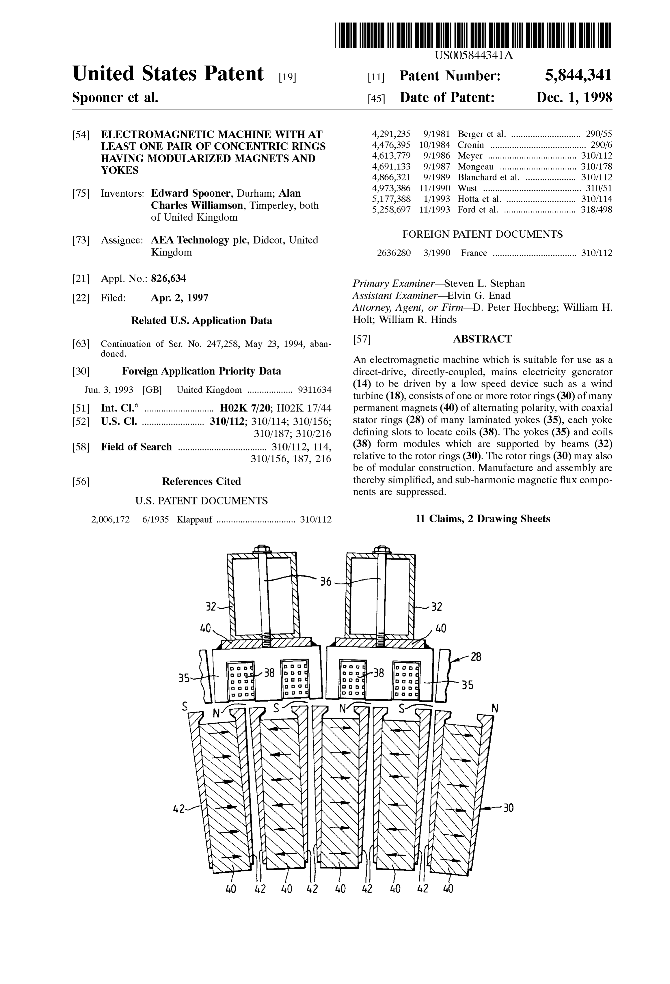
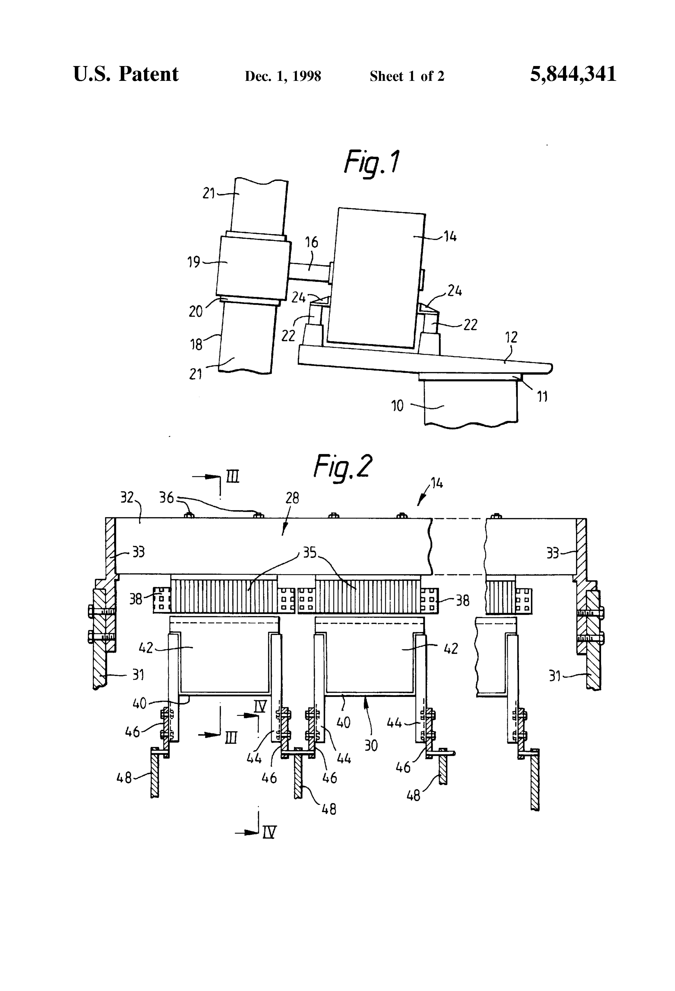
modular nature of the first and the Second rings Simplifies a generator 14 which is connected by a short shaft 16 to a both manufacture of the components and their assembly. wind rotor 18 with a teetering hub 19, pitch bearings 20, and In operation of the machine, whether as a generator or as blades 21. The generator 14 is of generally cylindrical form a motor, heat will be generated in the coils (due to Joule with a rotor inside a Stator; the Stator has circular end plates heating), and a smaller amount of heat will be generated in 31 (shown in FIG. 2), and the generator 14 is supported by the iron laminations of the yokes (due to hysteresis). It is two pairs of rubber Springs 22 connected to the end plates 31 thus apparent that means may be required to cool the Second by brackets 24, the Springs 22 of each pair being on opposite ring. In a preferred embodiment the beams which Support sides of the vertical plane in which the axis of the shaft 16 the yokes are in good thermal contact with the yokes, the lies (only two springs 22 are shown in FIG. 1). The tower 10, beams are hollow, and fans are used to cause a flow of air bearing 11, and pallet 12 and the wind rotor assembly 18, 19, through each beam to cool the beam and So the yokes and the 20, 21 are of known types, and are not the subject of the coils.
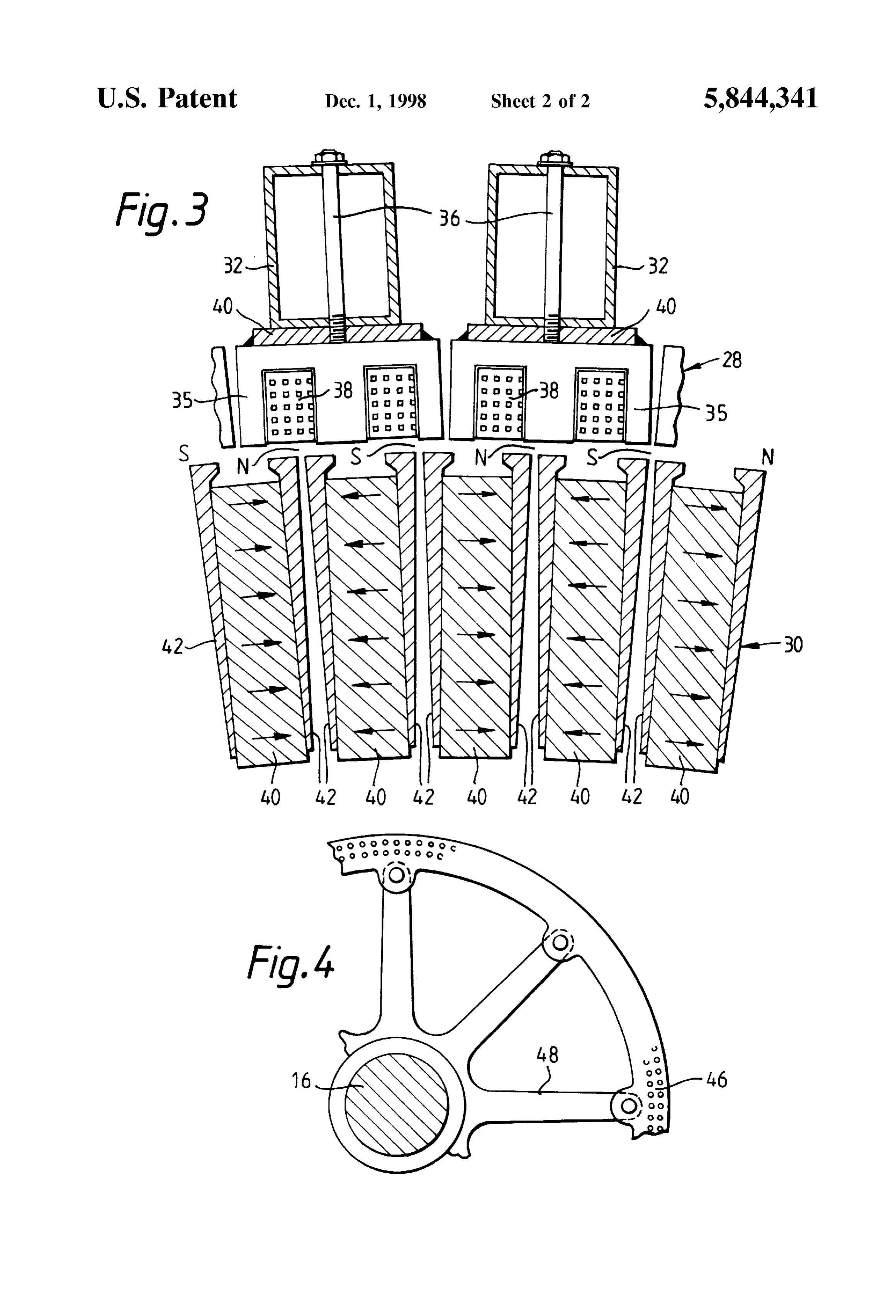
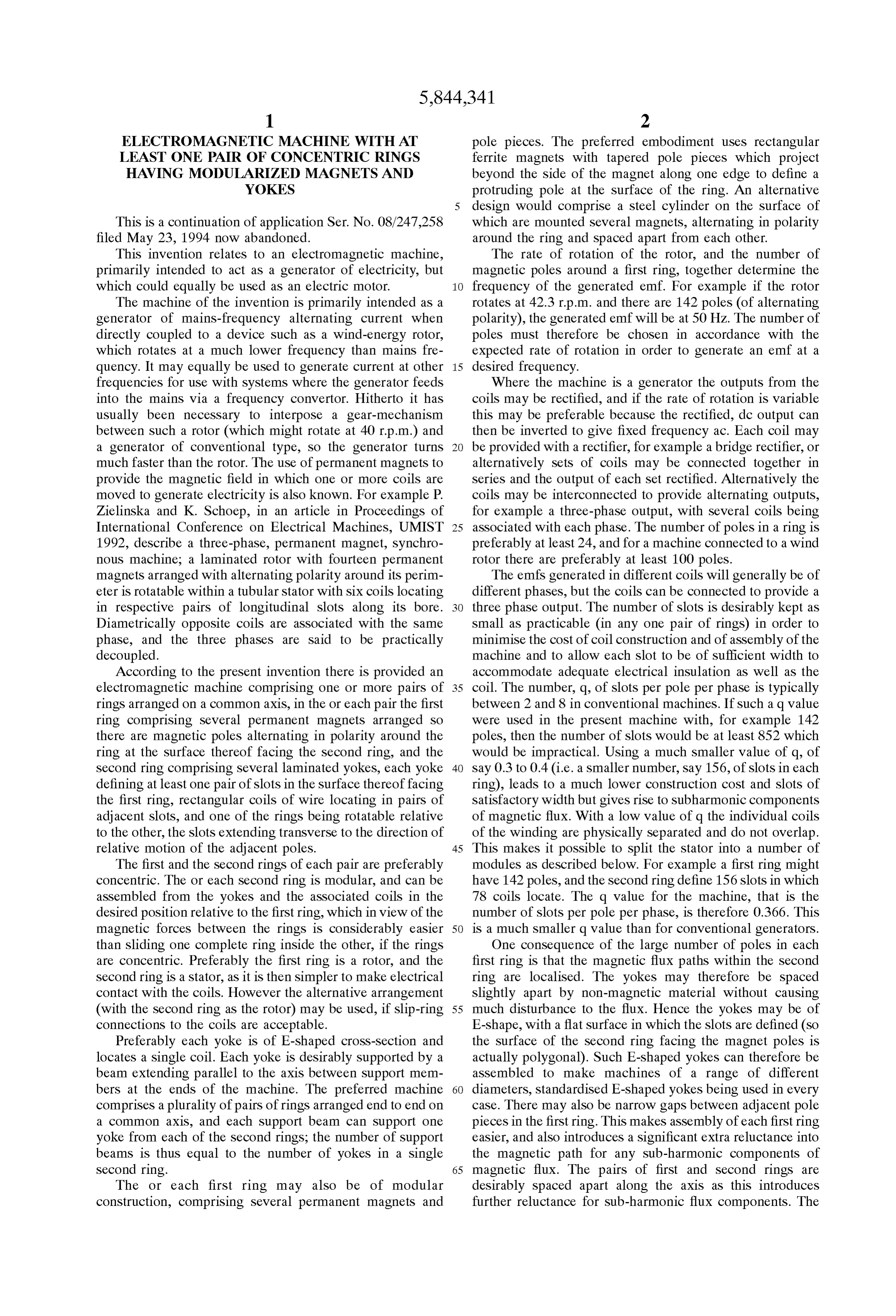
In operation the machine will also tend to produce invention. By way of example the wind rotor 18 might be of acoustic noise. This may be due to variations in the radial diameter 35.6 m, and for a wind speed of 12 m/s be expected magnetic forces between the rotor and the Stator; variations 15 kW. to rotate at 42.5 rp.m. giving a power output of about 400 in the tangential forces on the rotor and Stator poles during rotation; non-Synchronous current distributions in the coils, Referring now to FIG. 2, the generator 14 comprises a and imbalance between the loads on the three output phases. stator 28 and a rotor 30. The stator 28 consists of two In a machine with a plurality of first rings on a common axis circular end plates 31 and Seventy-eight longitudinally of rotation, along with a plurality of Second rings whose extending hollow rectangular Steel beams 32, each beam 32 yokes are Supported by common beams, many of the noise being connected to the periphery of each end plate 31 by end generating forces can be cancelled by displacing the first caps 33. Each beam 32 is of cross-section 75 mm by 50 mm, rings angularly relative to each other So the alternating with 4 mm thick walls. Five yokes 35 (only two are shown components of the forces cancel out. There may still be Some in full) are fixed by bolts 36 to each beam 32. Each yoke 35 residual elastic deformation in the beams, So clearly these is of laminated iron, of length 150 mm, and of E-shaped must be stiff in both deflection and torsion. It is also 25 croSS-Section So as to define two longitudinal Slots 20 mm desirable to damp any residual vibrations, for example by wide which locate a rectangular coil 38 of thirty-six turns of partly filling hollow beams with Sound-absorbing material, insulated, 2.5 mm diameter copper wire on a bobbin, taped or by inserting damping material Such as rubber between and resin-impregnated. Referring also to FIG. 3, each yoke adjacent beams. 35 is welded to a steel back-plate 40, to which the bolt 36 Where the electric machine is used as a generator con is attached. There is a narrow gap between adjacent yokes 35 nected to the mains, damping is required to overcome the around the circumference of the stator 28. The stator 28 thus tendency of a Synchronous machine to hunt around its consists of five rings Spaced apart along an axis, each ring equilibrium load angle. Desirably Such damping is provided consisting of Seventy-eight E-shaped yokes 35, So the inner by allowing the Stator to turn with respect to the Supporting Surface of each ring is in fact polygonal. Structure, and mechanically limiting and damping that turn 35 Referring again to FIG. 2, the rotor 30 consists of five ing motion. The damping may be provided by oil-filled rings, each ring consisting of 142 rectangular ferrite magnets dashpots, by the friction in leaf Springs, or alternatively by 40 (only two are shown in full) each with two tapered pole rubber mountings made of high hysteresis rubber. The Spring pieces 42 on either Side which project above the radially Stiffness in the torque reaction System should be low enough outermost surface of the magnets 40. Each magnet 40 is 150 to allow the Stator to turn through an angle of Several 40 mm long. Non-magnetic fixing brackets 44 are attached to degrees, preferably an angle equivalent to the angular Sepa the ends of each magnet 40 and are bolted onto a ring 46 ration of a plurality of adjacent poles, for example two or which is also preferably non-magnetic. Referring also to three poles, or even as much as ten or more poles. FIG. 4, all the rings 46 are connected by rotor spiders 48 to In order to avoid excessive transient torque and current the shaft 16, to which the spiders 48 are clamped by taper when the generator is first connected to the mains Supply, the 45 hubs. Referring also to FIG. 3, the magnets 40 are arranged generated emfshould of course be as close as possible to the alternating in polarity around each ring, So that the project mains in magnitude, phase, and frequency. If they are not ing pairs of ends of the pole pieces 42 also alternate in perfectly matched then a transient current will flow, causing polarity. There is a narrow gap between adjacent magnet a transient torque which will tend to change the relative pole pieces 42 around the circumference of the rotor 30. The angular Velocity of the rotor and Stator towards Synchronous 50 rotor 30 has a diameter of 1.8 m, and there is a radial gap of Speed. If the generator is damped as described above, then width 2.5 mm between the outer ends of the pole pieces 42 the Stator will turn against the elastic compliance of the and the inner Surface of the stator 28.
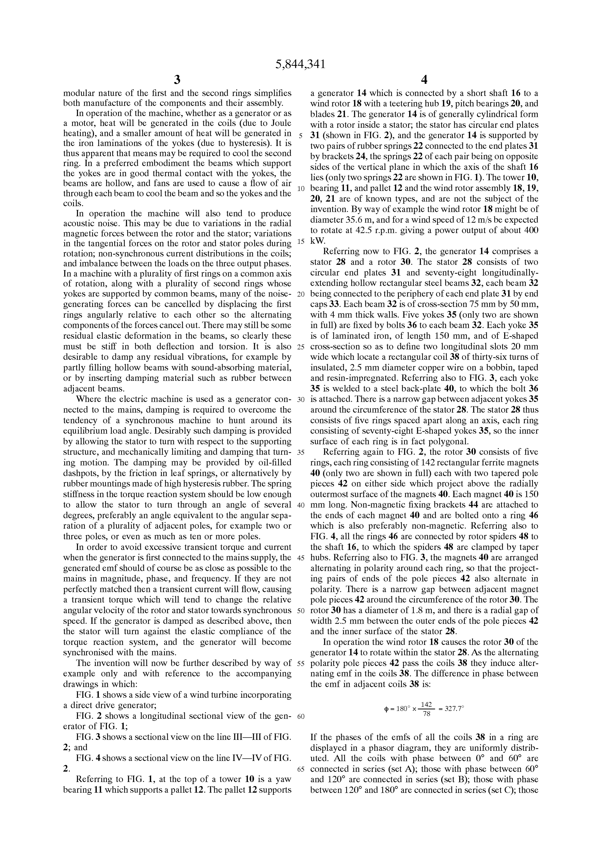
torque reaction System, and the generator will become In operation the wind rotor 18 causes the rotor 30 of the Synchronised with the mains. generator 14 to rotate within the Stator 28. AS the alternating The invention will now be further described by way of 55 polarity pole pieces 42 pass the coils 38 they induce alter example only and with reference to the accompanying nating emf in the coils 38. The difference in phase between drawings in which: the emf in adjacent coils 38 is:
FIG. 1 shows a side view of a wind turbine incorporating a direct drive generator, (p = 180° x- 78 = 327.7 FIG. 2 shows a longitudinal Sectional view of the gen 60 erator of FIG. 1;
FIG.3 shows a sectional view on the line III-III of FIG. If the phases of the emfs of all the coils 38 in a ring are 2, and displayed in a phasor diagram, they are uniformly distrib FIG. 4 shows a sectional view on the line IV-IV of FIG. uted. All the coils with phase between 0 and 60 are 2. 65 connected in series (set A); those with phase between 60 Referring to FIG. 1, at the top of a tower 10 is a yaw and 120° are connected in series (set B); those with phase bearing 11 which Supports a pallet 12. The pallet 12 Supports between 120° and 180° are connected in series (set C); those
Page 6
S 6 with phase between 180 and 240 are connected in series Second ring having opposing first and Second Surfaces (Set D); etcetera. Set D can then be connected in reverse, in Separated by a gap wherein:
Series with Set A, and Similarly for the other phase Sets. Said first ring comprises magnet modules Separated by Alternatively, because in this embodiment each Set consists circumferential gaps from adjacent magnet modules, of the same number (thirteen) of coils 38, sets such as A and each of Said magnet modules comprising a permanent D (in reverse) can be connected in parallel to give a lower magnet and two pole pieces, one of Said pole pieces output voltage. being on one side of Said permanent magnet and the The induced emf of each coil (at the rate of rotation of other of Said pole pieces being on the other Side of Said 42.3 rp.m.) is about 45 V; the voltage across each set of permanent magnet, wherein each of Said pole pieces thirteen coils is about 560 V, taking into account the spread has a Side facing one of the circumferential gaps of phases. The generator 14 has five such rings of yokes 35 opposite a Side facing the permanent magnet, each and coils 38, so there are ten such sets of coils which may magnet being magnetized in a tangential direction be connected in a variety of different arrangements to give transverse to Said common axis, the polarity of the different output Voltages. magnets being Such that there are magnetic poles The generator 14 can be connected into a mains grid, and 15 alternating in polarity around Said first ring at Said first the resilience in the rubber mountings 22 for the stator 28 is Surface, the magnetization of the permanent magnet in sufficient to allow the stator 28 to turn in response to the a Said magnet module being oppositely directed to the transient torque when initially connected, and then to come magnetization of the permanent magnets in both of the into Synchronism with the mains frequency. It may be adjacent magnet modules, and desirable to be able to adjust the induced emf produced by Said Second ring comprises Several laminated yokes, each the generator 14, firstly for Synchronising to the Supply, and yoke defining at least one pair of Slots in Said Second secondly for reactive power control. This can be achieved by Surface, Said slots extending parallel to Said common displacing the rotor 30 axially relative to the stator 28, so axis, rectangular coils of wire located in pairs of modifying the magnetic coupling. This will affect both the adjacent slots, Said yoke and Said coils in Said yoke emf and the reactances. An alternative way of adjusting the 25 defining a yoke module Separated by circumferential reactive power would be to change the number of coils 38 gaps from adjacent yoke modules, in each set (A, B, C, etc) which are connected in Series to wherein one of Said first and Second rings of each of Said provide the output voltage (so some of the coils 38 are not one or more concentric pairs being continuously rotat used). The resulting asymmetry may however cause more able relative to the other of Said first and Second rings acoustic noise to be generated. about Said common axis.
When it is desired to stop rotation of the wind rotor 18 and 2. The machine as claimed in claim 1 wherein each yoke the generator rotor 30, either for routine or for emergency is of E-shaped cross-section, defining parallel-sided slots, shutdown, the braking may make use of the emf generated and locates a Single coil.
by the generator 14. One or each of the output phases could 3. The machine as claimed in claim 1 wherein the number be connected to earth via a capacitor in parallel with a 35 of Slots in any one Second ring is at least as many as the resistor. For example this might use a 0.4 ohm resistor in number of magnetic poles in the corresponding first ring. parallel with a 1 mP capacitor to brake down to about 10 4. The machine as claimed in claim 3 wherein the number r.p.m. At lower Speeds the capacitor would have little effect of slots and the number of poles are both at least 100. and the most effective braking would then be achieved by 5. The machine as claimed in claim 1 wherein, in the or Short-circuiting the generator. 40 each Second ring, the emfs induced in the coils are of It will be appreciated that the electrical machine described different phases, and the coils are connected So as to provide above may be modified in various ways while remaining three-phase alternating outputs, there being Several coils in within the Scope of the invention. For example the end caps each Second ring associated with each phase of the outputs. 33 might define apertures within which electrically-driven 6. The machine as claimed in claim 1 wherein, in the or fans are installed So a flow of coolant air flows along each 45 each pair of rings, the number of coils and the number of hollow beam 32 to remove heat from the coils 38 and yokes poles are Such that in operation the emfs induced in the coils 35. The yokes 35 and the magnet modules might be a by the magnets are not all co-phasal.
different length, for example they might both be of length 7. The machine as claimed in claim 1 wherein each pole 300 mm, each magnet module comprising two ferrite mag piece of each of Said magnet modules projects radially, Such nets 40 sandwiched end-to-end between 300 mm-long pole 50 that the Surface of the pole pieces are closer to the Second pieces. This will slightly reduce leakage of flux at the ends Surface than the Surface of the permanent magnet of the of the modules. Each yoke might define a different number Same magnet module.
of Slots, for example each yoke might define four longitu 8. The machine as claimed in claim 1 wherein at least one dinal slots So as to locate two coils 38 (So each yoke replaces of the one or more pairs of concentric rings has the first ring two adjacent yokes 35 of the generator 14). Furthermore the 55 axially movable relative to the Second ring. face of the yoke in which the slots are defined might be 9. The machine as claimed in claim 1 wherein, in said one curved, So the inner Surface of the ring is closer to being or more pairs of concentric rings in which one of Said first cylindrical. The generator 14 might be driven by the wind and Second rings is continuously rotatable relative to the rotor 18 in a different fashion, for example the generator 14 other, the other ring of each concentric pair can undergo might itself form the hub of the wind rotor. Where the hub 60 limited rotation, through less than half a revolution, and the incorporates the generator, the ring of magnets may be either machine includes means to apply a torque and damping to inside or Outside the ring of yokes. oppose this limited rotation.
We claim: 10. The machine as claimed in claim 1 wherein means are 1. An electromagnetic machine comprising one or more provided to cool each yoke module at the Surface thereof pairs of concentric rings arranged on a common axis, each 65 remote from the first ring.
pair of concentric rings having a modular first ring and a 11. An electromagnetic generator comprising one or more concentric modular Second ring, Said first ring and Said pairs of concentric rings arranged on a common axis, each
Page 7
of the rings in the one or more pairs being of modular extending parallel to the axis, and rectangular coils of construction and having the following features: wire locating in pairs of adjacent Slots, each yoke with (a) the first ring comprising several magnet modules its coil or coils defining a yoke module, and each yoke Separated by circumferential gaps from adjacent mag- module being Separated by circumferential gaps from net modules, each of said magnet modules comprising 5 adjacent yoke modules, a permanent magnet and two radially projecting pole (c) the first ring being rotatable about the axis; and pieces wherein the permanent magnet is located between the pole pieces, each magnet being magne (d) the number of coils and the number of poles are such tized in a tangential direction transverse to Said com- that in operation the emf induced in every coil in the mon axis, each permanent magnet in one of Said 10 Second ring is of a different phase; magnet modules having a different polarity than both of wherein the first ring in at least one of the one or more the permanent magnets in adjacent magnet modules, pairs of concentric rings are axially displaceable rela (b) the Second ring comprising Several laminated yokes, tive to the Second ring.
each yoke defining at least one pair of parallel-sided slots in a Surface thereof facing the first ring, the slots k . . . .
Page 8
UNITED STATES PATENT AND TRADEMARK OFFICE
CERTIFICATE OF CORRECTION
INVENTOR(S) : Edward Spooner and Alan Charles Williamson It is certified that error appears in the above-indentified patent and that said Letters Patent is hereby Corrected as shown below:
On the title page, item 73) Assign should read as follows: The Secretary of State for Trade and
Industry in Her Britannic Majesty's
Government of the United Kingdom of
Great Britain and Northern Ireland,
London, United Kingdom
Signed and Sealed this
Ninth Day of November, 1999
Q. TODI) DICKINSON
Attesting Officer At fing Crni Ji is, iotic i Paints and Tralenarks
Provenance
- Collection
- Patents citing this work
- Current assignee
- Ricardo AEA Ltd
- Original assignee
- AEA Technology PLC
- Pages
- 8
- Method
- pdftotext (the PDF's own text layer) + pdftoppm 300dpi page scans
- Patent office record
- patents.google.com →
- Source
- Google Patents citing-documents table
- Inventors
- Edward Spooner; Alan Charles Williamson; AEA Technology PLC
- Published
- 1998-12-01
- Transcribed from
- patentimages.storage.googleapis.com →