patent · US4061926
Wind driven electrical generator
6 December 1977
Page 1 — bibliographic record
United States Patent (19) (11) 4,061,926 Peed 45 Dec. 6, 1977 54 WIND DRIVEN ELECTRICAL GENERATOR 56) References Cited
76) Inventor: Paul V. Peed, 1053 North Ave., 3,697,765 10/1972 Carini..................................... 290/44 Sacramento, Calif. 95838 3,938,907 2/1976 Magoveny et al. ... 415/4 3,974,396 8/1976 Schonball .............. ... 290/54
Primary Examiner-Robert K. Schaefer (21) Appl. No.: 669,961 Assistant Examiner-Eugene S. Indyk Attorney, Agent, or Firm-Blair & Brown
An electric generating system in which oppositely ro tating wind driven wheels are used, one to drive the (51) Int. Cl. F03D 9/00; H02P 9/04 rotor and one to drive the stator of an electric genera 52 U.S. C. ...................................................... 290/55 tor.
58 Field of Search ....................... 290/43, 44, 54, 55;
415/2, 3, 4; 308/221, 230 2 Claims, 7 Drawing Figures
Page 2
Drawing sheet — no readable text.
Page 3
Drawing sheet — no readable text.
Page 4
Drawing sheet — no readable text.
Page 5
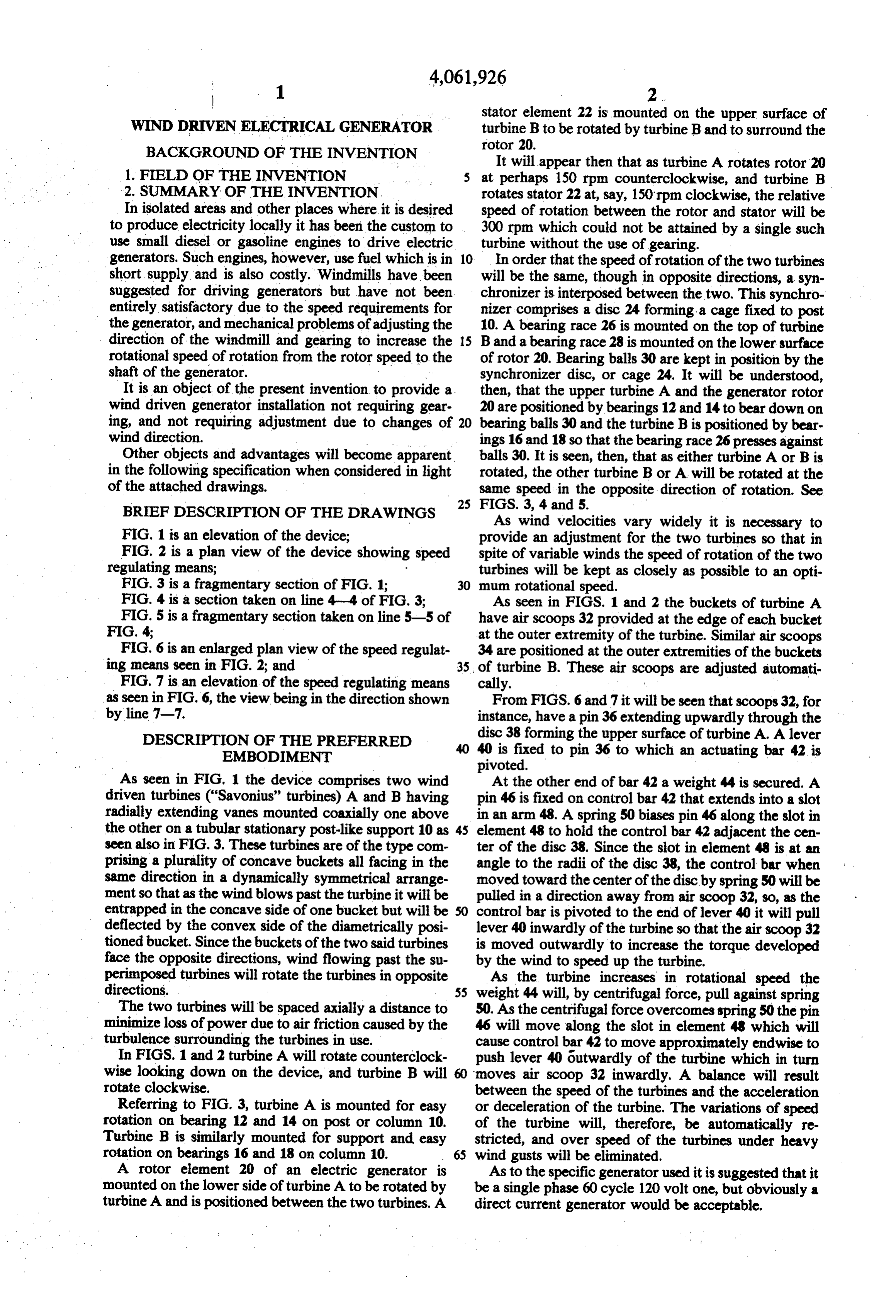
stator element 22 is mounted on the upper surface of
WIND DRIVEN ELECTRICAL GENERATOR turbine B to be rotated by turbine Band to surround the BACKGROUND OF THE INVENTION rotor 20.
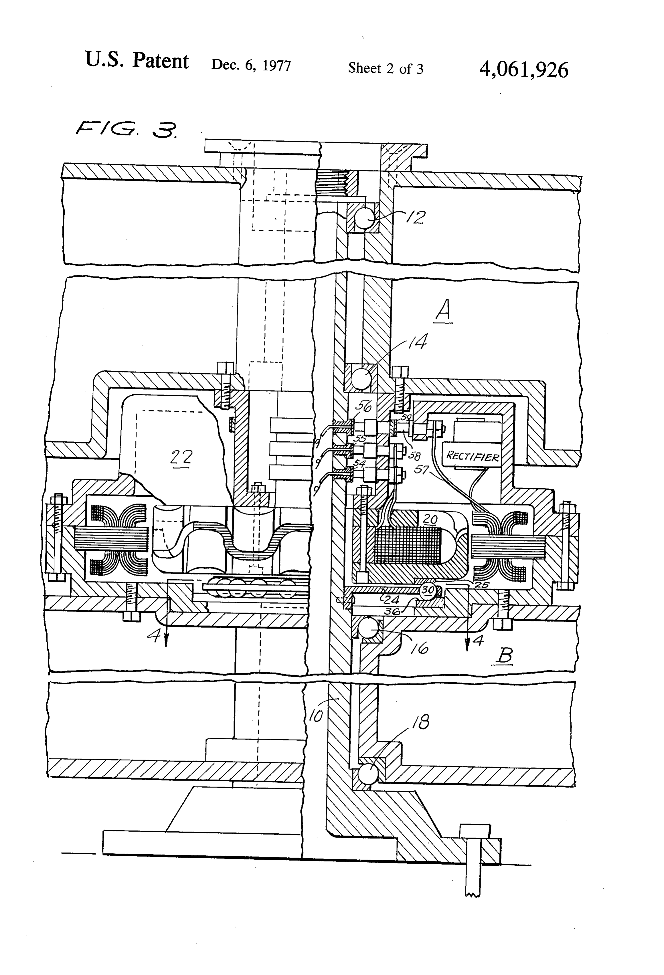
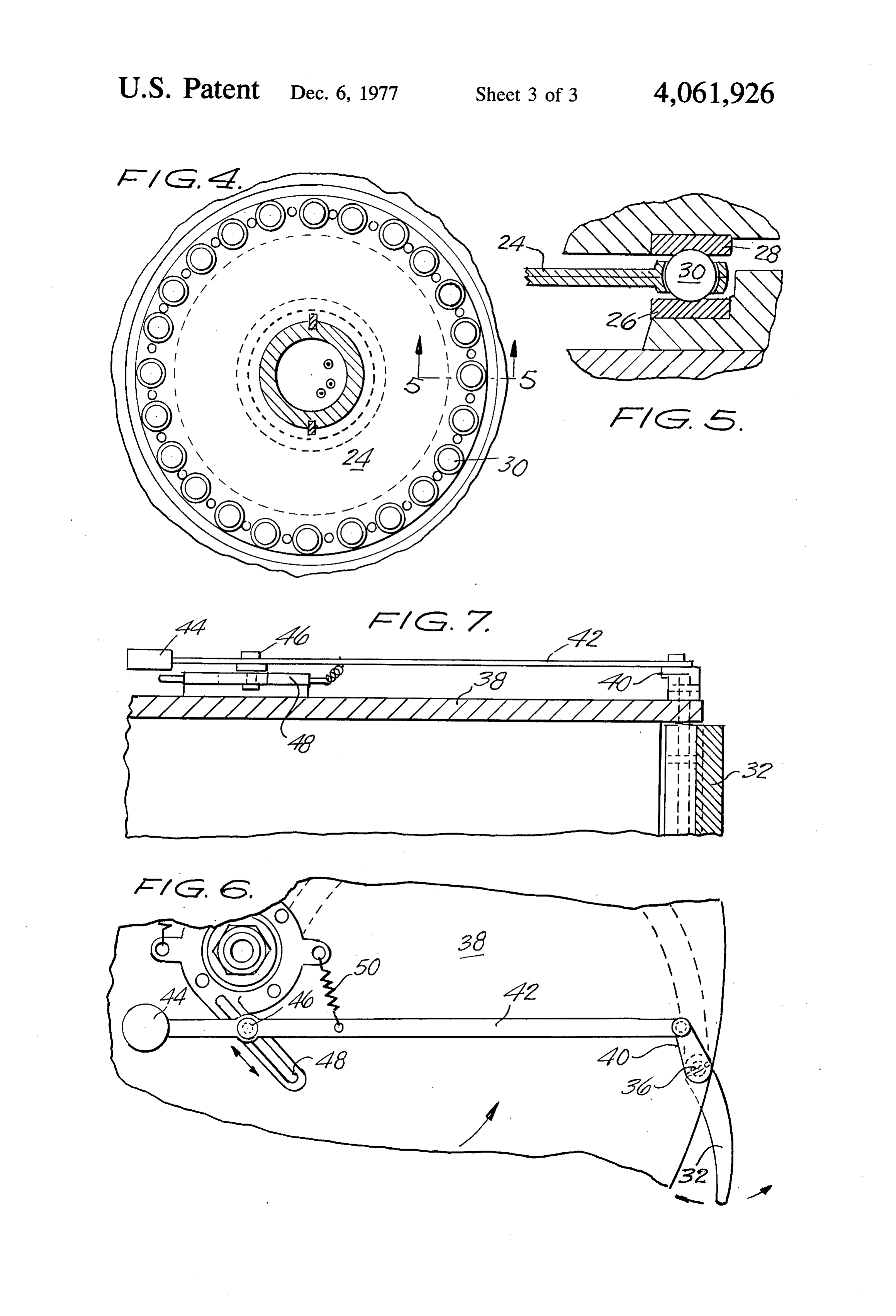
It will appear then that as turbine A rotates rotor 20 1. FIELD OF THE INVENTION 5 at perhaps 150 rpm counterclockwise, and turbine B 2. SUMMARY OF THE INVENTION rotates stator 22 at, say, 150 rpm clockwise, the relative In isolated areas and other places where it is desired speed of rotation between the rotor and stator will be to produce electricity locally it has been the custom to 300 rpm which could not be attained by a single such use small diesel or gasoline engines to drive electric turbine without the use of gearing. generators. Such engines, however, use fuel which is in 10 In order that the speed of rotation of the two turbines short supply, and is also costly. Windmills have been will be the same, though in opposite directions, a syn suggested for driving generators but have not been chronizer is interposed between the two. This synchro entirely satisfactory due to the speed requirements for nizer comprises a disc 24 forming a cage fixed to post the generator, and mechanical problems of adjusting the 10. A bearing race 26 is mounted on the top of turbine direction of the windmill and gearing to increase the 15 Band a bearing race 28 is mounted on the lower surface rotational speed of rotation from the rotor speed to the of rotor 20. Bearing balls 30 are kept in position by the shaft of the generator. synchronizer disc, or cage 24. It will be understood, It is an object of the present invention to provide a then, that the upper turbine A and the generator rotor wind driven generator installation not requiring gear 20 are positioned by bearings 12 and 14 to bear down on ing, and not requiring adjustment due to changes of 20 bearing balls 30 and the turbine B is positioned by bear wind direction. ings 16 and 18 so that the bearing race 26 presses against Other objects and advantages will become apparent. balls 30. It is seen, then, that as either turbine A or B is in the following specification when considered in light rotated, the other turbine B or A will be rotated at the of the attached drawings. same speed in the opposite direction of rotation. See BRIEF DESCRIPTION OF THE DRAWINGs FIGS. 3, 4 and 5.
As wind velocities vary widely it is necessary to
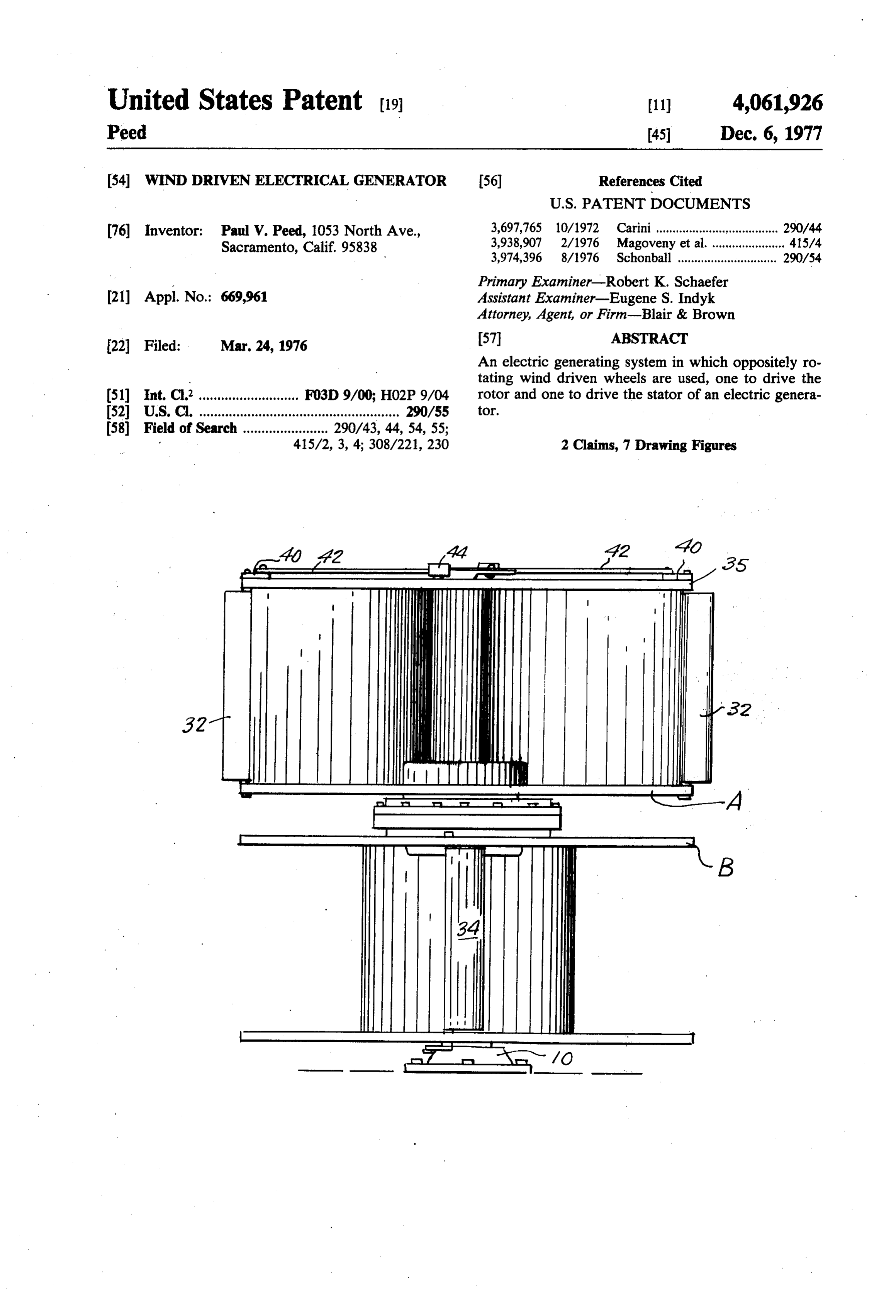
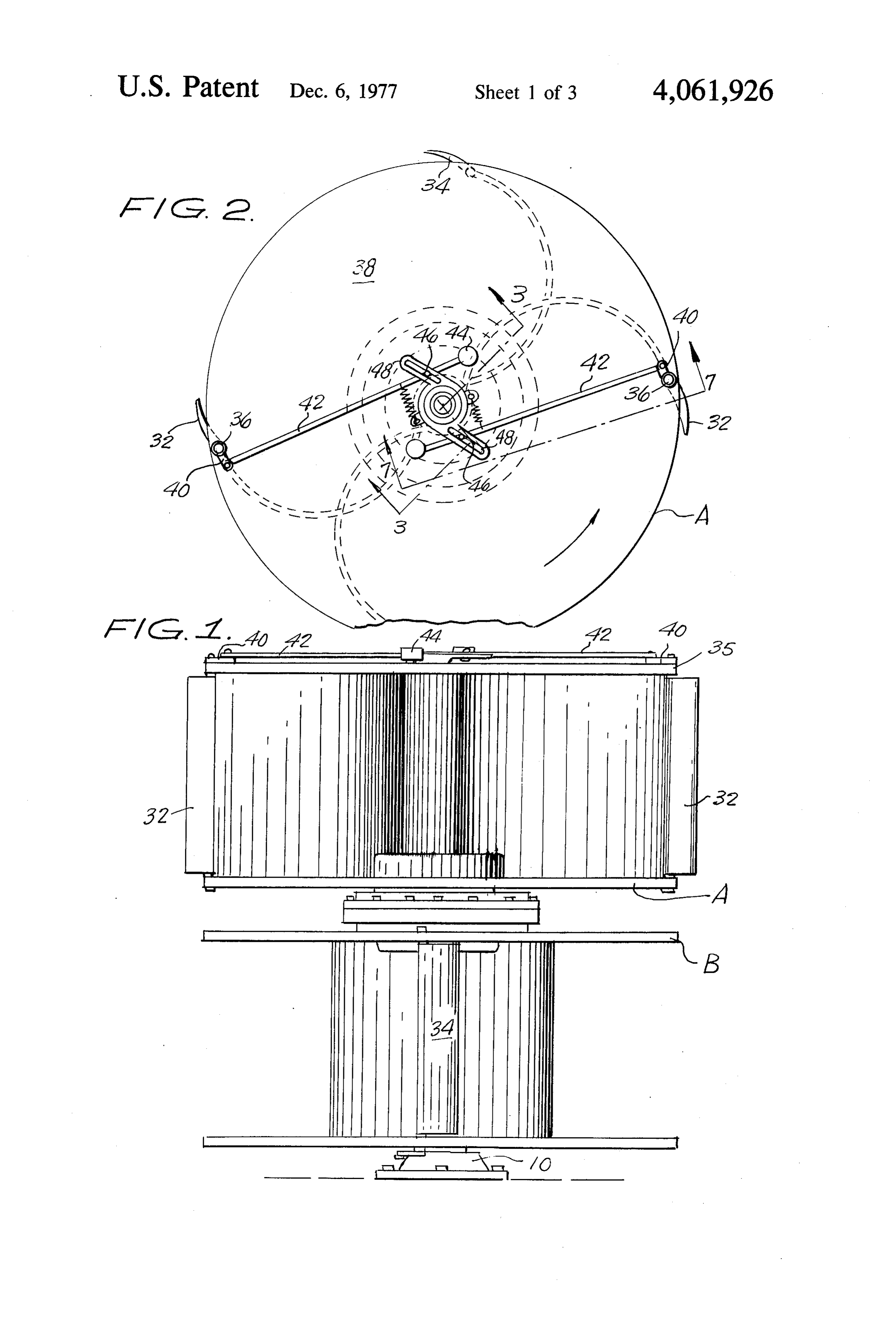
FIG. 1 is an elevation of the device; provide an adjustment for the two turbines so that in FIG. 2 is a plan view of the device showing speed spite of variable winds the speed of rotation of the two regulating means; turbines will be kept as closely as possible to an opti FIG. 3 is a fragmentary section of FIG. 1; 30 mum rotational speed.
FIG. 4 is a section taken on line 4-4 of FIG. 3; As seen in FIGS. 1 and 2 the buckets of turbine A FIG. 5 is a fragmentary section taken on line 5-5 of have air scoops 32 provided at the edge of each bucket FIG. 4; at the outer extremity of the turbine. Similar air scoops FIG. 6 is an enlarged plan view of the speed regulat 34 are positioned at the outer extremities of the buckets ing means seen in FIG. 2; and 35 of turbine B. These air scoops are adjusted automati FIG. 7 is an elevation of the speed regulating means cally.
as seen in FIG. 6, the view being in the direction shown From FIGS. 6 and 7 it will be seen that scoops 32, for by line 7-7. instance, have a pin 36 extending upwardly through the DESCRIPTION OF THE PREFERRED disc 38 forming the upper surface of turbine A. A lever 40 is fixed to pin 36 to which an actuating bar 42 is
As seen in FIG, 1 the device comprises two wind At the other end of bar 42 a weight 44 is secured. A driven turbines ("Savonius' turbines) A and B having pin 46 is fixed on control bar 42 that extends into a slot radially extending vanes mounted coaxially one above in an arm 48. A spring 50 biases pin 46 along the slot in the other on a tubular stationary post-like support 10 as 45 element 48 to hold the control bar 42 adjacent the cen seen also in FIG. 3. These turbines are of the type com ter of the disc 38. Since the slot in element 48 is at an prising a plurality of concave buckets all facing in the angle to the radii of the disc 38, the control bar when same direction in a dynamically symmetrical arrange moved toward the center of the disc by spring 50 will be ment so that as the wind blows past the turbine it will be pulled in a direction away from air scoop 32, so, as the entrapped in the concave side of one bucket but will be control bar is pivoted to the end of lever 40 it will pull deflected by the convex side of the diametrically posi lever 40 inwardly of the turbine so that the air scoop 32 tioned bucket. Since the buckets of the two said turbines is moved outwardly to increase the torque developed face the opposite directions, wind flowing past the su by the wind to speed up the turbine. perimposed turbines will rotate the turbines in opposite As the turbine increases in rotational speed the directions. 55 weight 44 will, by centrifugal force, pull against spring The two turbines will be spaced axially a distance to 50. As the centrifugal force overcomes spring 50 the pin minimize loss of power due to air friction caused by the 46 will move along the slot in element 48 which will - turbulence surrounding the turbines in use. cause control bar 42 to move approximately endwise to In FIGS. 1 and 2 turbine A will rotate counterclock push lever 40 outwardly of the turbine which in turn wise looking down on the device, and turbine B will moves air scoop 32 inwardly. A balance will result rotate clockwise. between the speed of the turbines and the acceleration Referring to FIG. 3, turbine A is mounted for easy or deceleration of the turbine. The variations of speed rotation on bearing 12 and 14 on post or column 10. of the turbine will, therefore, be automatically re Turbine B is similarly mounted for support and easy stricted, and over speed of the turbines under heavy rotation on bearings 16 and 18 on column 10. 65 wind gusts will be eliminated.
A rotor element 20 of an electric generator is As to the specific generator used it is suggested that it mounted on the lower side of turbine A to be rotated by be a single phase 60 cycle 120 volt one, but obviously a turbine A and is positioned between the two turbines. A direct current generator would be acceptable.
Page 6
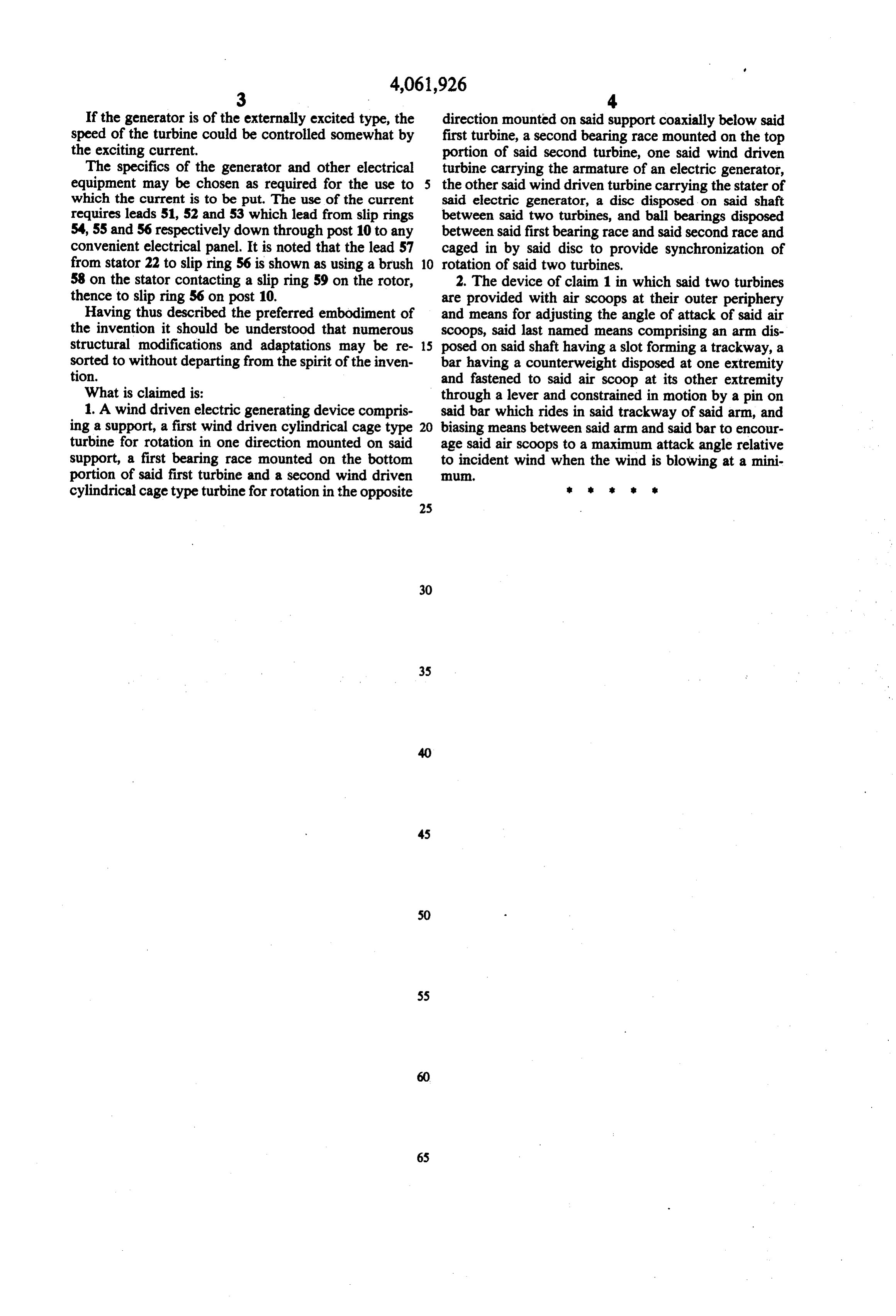
If the generator is of the externally excited type, the direction mounted on said support coaxially below said speed of the turbine could be controlled somewhat by first turbine, a second bearing race mounted on the top the exciting current. portion of said second turbine, one said wind driven The specifics of the generator and other electrical turbine carrying the armature of an electric generator, equipment may be chosen as required for the use to the other said wind driven turbine carrying the stater of which the current is to be put. The use of the current said electric generator, a disc disposed on said shaft requires leads 51, 52 and 53 which lead from slip rings between said two turbines, and ball bearings disposed 54, 55 and 56 respectively down through post 10 to any between said first bearing race and said second race and convenient electrical panel. It is noted that the lead 57 caged in by said disc to provide synchronization of from stator 22 to slip ring 56 is shown as using a brush 10 rotation of said two turbines. 58 on the stator contacting a slip ring 59 on the rotor, 2. The device of claim 1 in which said two turbines thence to slip ring 56 on post 10. are provided with air scoops at their outer periphery Having thus described the preferred embodiment of and means for adjusting the angle of attack of said air the invention it should be understood that numerous scoops, said last named means comprising an arm dis structural modifications and adaptations may be re 15 posed on said shaft having a slot forming a trackway, a sorted to without departing from the spirit of the inven bar having a counterweight disposed at one extremity tion. and fastened to said air scoop at its other extremity What is claimed is: through a lever and constrained in motion by a pin on 1. A wind driven electric generating device compris said bar which rides in said trackway of said arm, and ing a support, a first wind driven cylindrical cage type 20 biasing means between said arm and said bar to encour turbine for rotation in one direction mounted on said age said air scoops to a maximum attack angle relative support, a first bearing race mounted on the bottom to incident wind when the wind is blowing at a mini portion of said first turbine and a second wind driven cylindrical cage type turbine for rotation in the opposite
Provenance
- Collection
- Cited prior art
- Original PDF
- patentimages.storage.googleapis.com →
- Filed
- 1976-03-24
- Pages
- 6
- Method
- pdftotext (the PDF's own text layer) + pdftoppm 300dpi page scans
- Source
- Google Patents bibliographic record
- Granted
- 1977-12-06
- Inventors
- Paul V. Peed
- Transcribed from
- patentimages.storage.googleapis.com →