patent · US5410997
High performance automotive engine gasket and method of sealing a high performance engine
2 May 1995
Page 1 — bibliographic record
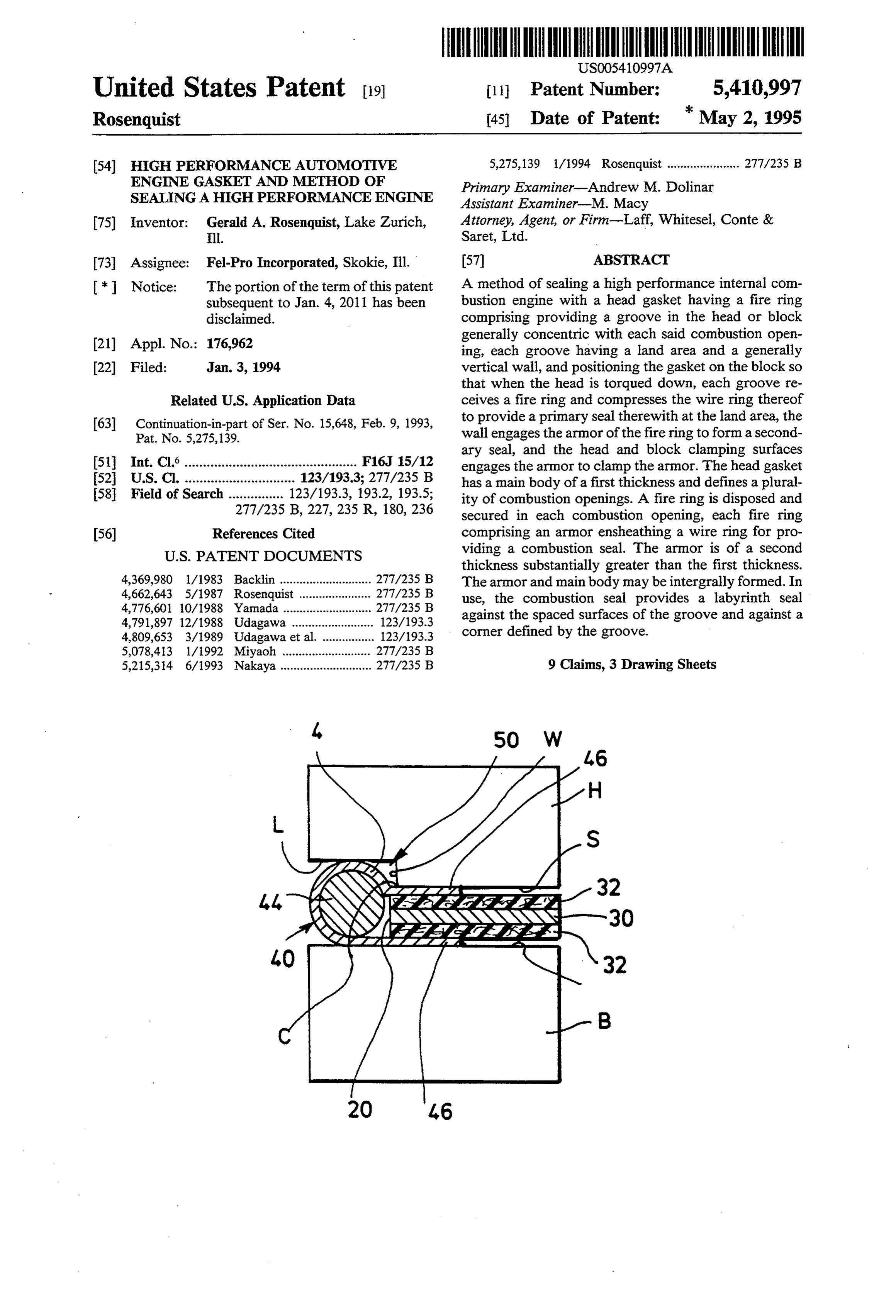
United States Patent (19) 11 Patent Number: 5,410,997 Rosenquist 45 Date of Patent: k May 2, 1995
54 HGH PERFORMANCE AUTOMOTIVE 5,275,139 1/1994 Rosenquist ...................... 277/235 B ENGINE GASKET AND METHOD OF Primary Examiner-Andrew M. Dolinar SEALNGA HIGH PERFORMANCE ENGINE Assistant Examiner-M. Macy 75 Inventor: Gerald A. Rosenquist, Lake Zurich, Attorney, Agent, or Firm-Laff, Whitesel, Conte & Ill. Saret, Ltd.
73) Assignee: Fel-Pro Incorporated, Skokie, Ill. 57 ABSTRACT * Notice: The portion of the term of this patent A method of sealing a high performance internal com subsequent to Jan. 4, 2011 has been bustion engine with a head gasket having a fire ring disclaimed. comprising providing a groove in the head or block 21) Appl. No.: 176,962 generally concentric with each said combustion open ing, each groove having a land area and a generally 22) Filed: Jan. 3, 1994 vertical wall, and positioning the gasket on the block so that when the head is torqued down, each groove re
Related U.S. Application Data ceives a fire ring and compresses the wire ring thereof 63 Continuation-in-part of Ser. No. 15,648, Feb. 9, 1993, to provide a primary seal therewith at the land area, the Pat. No. 5,275,139. wall engages the armor of the fire ring to form a second ary seal, and the head and block clamping surfaces 51 Int. Cl. ............................................... F16J 15/12 engages the armor to clamp the armor. The head gasket 52 U.S. Cl. .............................. 123/1933; 277/235 B has a main body of a first thickness and defines a plural 58 Field of Search ............... 123/193.3, 1932, 193.5; ity of combustion openings. A fire ring is disposed and 277/235 B, 227, 235 R, 180, 236 secured in each combustion opening, each fire ring 56) References Cited comprising an armor ensheathing a wire ring for pro
thickness substantially greater than the first thickness.
4,369,980 1/1983 Backlin ............................ 277/235 B The armor and main body may be intergrally formed. In 4,662,643 5/1987 Rosenquist . ... 277/235 B use, the combustion seal provides a labyrinth seal 4,776,601 10/1988 Yamada ....... ... 277/235 B against the spaced surfaces of the groove and against a 4,791,897 12/1988 Udagawa ......................... 123/193.3 corner defined by the groove.
5,078,413 1/1992 Miyaoh ... ... 277/235 B 5,215,314 6/1993 Nakaya............................ 277/235 B 9 Claims, 3 Drawing Sheets
Page 2
Drawing sheet — no readable text.
Page 3
Drawing sheet — no readable text.
Page 4
Drawing sheet — no readable text.
Page 5
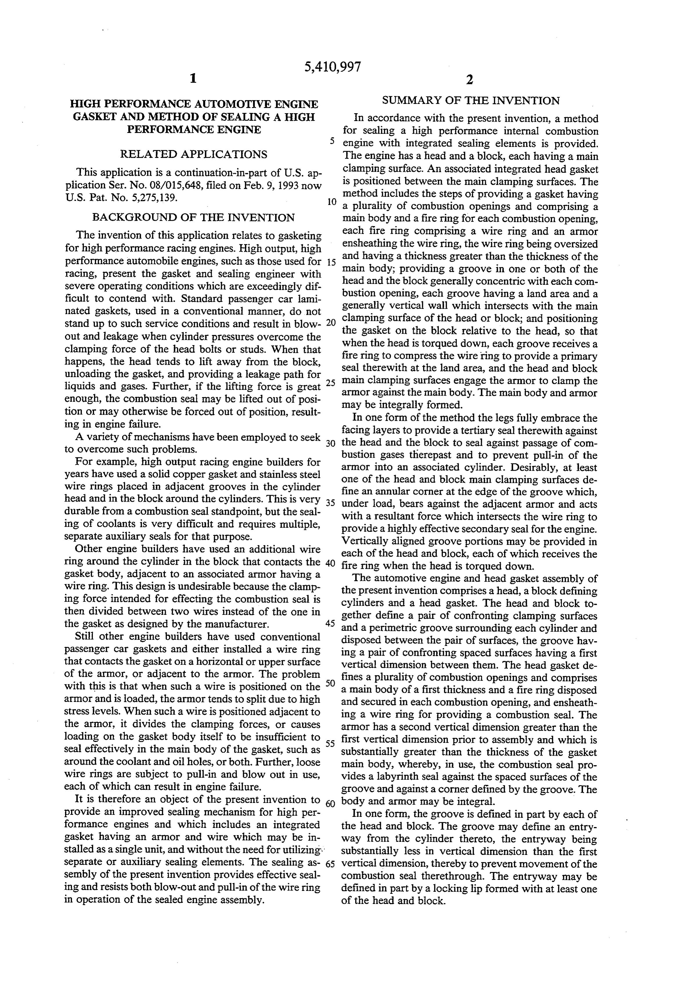
HIGH PERFORMANCE AUTOMOTIVE ENGINE SUMMARY OF THE INVENTION GASKET AND METHOD OF SEALING A HIGH In accordance with the present invention, a method PERFORMANCE ENGINE for sealing a high performance internal combustion engine with integrated sealing elements is provided.
RELATED APPLICATIONS The engine has a head and a block, each having a main This application is a continuation-in-part of U.S. ap clamping surface. An associated integrated head gasket plication Ser. No. 08/015,648, filed on Feb. 9, 1993 now method is positioned between the main clamping surfaces. The U.S. Pat. No. 5,275,139. 10 includes the steps of providing a gasket having a plurality of combustion openings and comprising a
BACKGROUND OF THE INVENTION main body and a fire ring for each combustion opening, The invention of this application relates to gasketing each fire ring comprising a wire ring and an armor for high performance racing engines. High output, high ensheathing the wire ring, the wire ring being oversized performance automobile engines, such as those used for 15 and having a thickness greater than the thickness of the racing, present the gasket and sealing engineer with main body; providing a groove in one or both of the severe operating conditions which are exceedingly dif head andopening, the block generally concentric with each com ficult to contend with. Standard passenger car lami bustion each groove having a land area and a nated gaskets, used in a conventional manner, do not clamping surface ofwall generally vertical which intersects with the main stand up to such service conditions and result in blow the gasket on the blockhead 20 the or block; and positioning relative to the head, so that out and leakage when cylinder pressures overcome the when the head is torqued down, each groove receives a clamping force of the head bolts or studs. When that fire ring to compress the wire ring to provide a primary happens, the head tends to lift away from the block, seal therewith at the land area, and the head and block unloading the gasket, and providing a leakage path for main clamping surfaces engage the armor to clamp the liquids and gases. Further, if the lifting force is great 25 armor against the main body. The main body and armor enough, the combustion seal may be lifted out of posi tion or may otherwise be forced out of position, result may In be integrally formed.
one form of the method the legs fully embrace the ing in engine failure. facing layers to provide a tertiary seal therewith against A variety of mechanisms have been employed to seek 30 the head and the block to seal against passage of com to overcome such problems.
For example, high output racing engine builders for armor into an therepast bustion gases and to prevent pull-in of the years have used a solid copper gasket and stainless steel one of the head and blockcylinder.
associated main
Desirably, at least clamping surfaces de wire rings placed in adjacent grooves in the cylinder fine an annular corner at the edge of the groove which, head and in the block around the cylinders. This is very 35 under load, bears against the adjacent armor and durable from a combustion seal standpoint, but the seal with a resultant force which intersects the wire ringacts to ing of coolants is very difficult and requires multiple, provide a highly effective secondary seal for the engine. separate auxiliary seals for that purpose. Vertically aligned groove portions may be provided in Other engine builders have used an additional wire each of the head and block, each of which receives the ring around the cylinder in the block that contacts the gasket body, adjacent to an associated armor having a fireThe ring when the head is torqued down. automotive engine and head gasket assembly of wire ring. This design is undesirable because the clamp the present invention comprises ahead, a block defining ing force intended for effecting the combustion seal is cylinders and a head gasket. The head and block to then divided between two wires instead of the one in gether define a pair of confronting clamping surfaces the gasket as designed by the manufacturer. 45 and a perimetric groove surrounding each cylinder and
Still other engine builders have used conventional disposed between the pair of surfaces, the groove hav passenger car gaskets and either installed a wire ring ing a pair of confronting spaced surfaces having a first that contacts the gasket on a horizontal or upper surface vertical dimension between them. The head gasket de of the armor, or adjacent to the armor. The problem fines a plurality of combustion openings and comprises with this is that when such a wire is positioned on the 50 a main body of a first thickness and a fire ring disposed armor and is loaded, the armor tends to split due to high and secured in each combustion opening, and ensheath stress levels. When such a wire is positioned adjacent to ing a wire ring for providing a combustion seal. The the armor, it divides the clamping forces, or causes armor has a second vertical dimension greater than the loading on the gasket body itself to be insufficient to 55 first vertical dimension prior to assembly and which is seal effectively in the main body of the gasket, such as substantially greater than the thickness of the gasket around the coolant and oil holes, or both. Further, loose main body, whereby, in use, the combustion seal pro wire rings are subject to pull-in and blow out in use, vides a labyrinth seal against the spaced surfaces of the each of which can result in engine failure. groove and against a corner defined by the groove. The It is therefore an object of the present invention to body and armor may be integral.
provide an improved sealing mechanism for high per In one form, the groove is defined in part by each of formance engines and which includes an integrated the head and block. The groove may define an entry gasket having an armor and wire which may be in way from the cylinder thereto, the entryway being stalled as a single unit, and without the need for utilizing substantially less in vertical dimension than the first separate or auxiliary sealing elements. The sealing as 65 vertical dimension, thereby to prevent movement of the sembly of the present invention provides effective seal combustion seal therethrough. The entryway may be ing and resists both blow-out and pull-in of the wire ring defined in part by a locking lip formed with at least one in operation of the sealed engine assembly. of the head and block.
Page 6
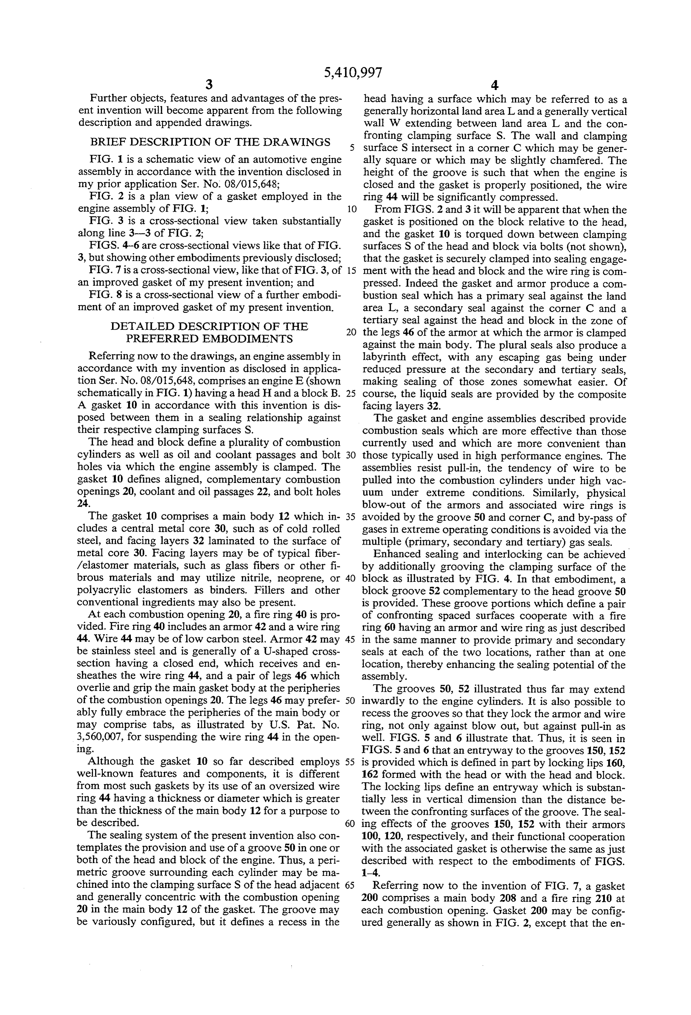
Further objects, features and advantages of the pres head having a surface which may be referred to as a ent invention will become apparent from the following generally horizontal land area L and a generally vertical description and appended drawings. wall W extending between land area L and the con BRIEF DESCRIPTION OF THE ORAWINGS fronting clamping surface S. The wall and clamping surface S intersect in a corner C which may be gener
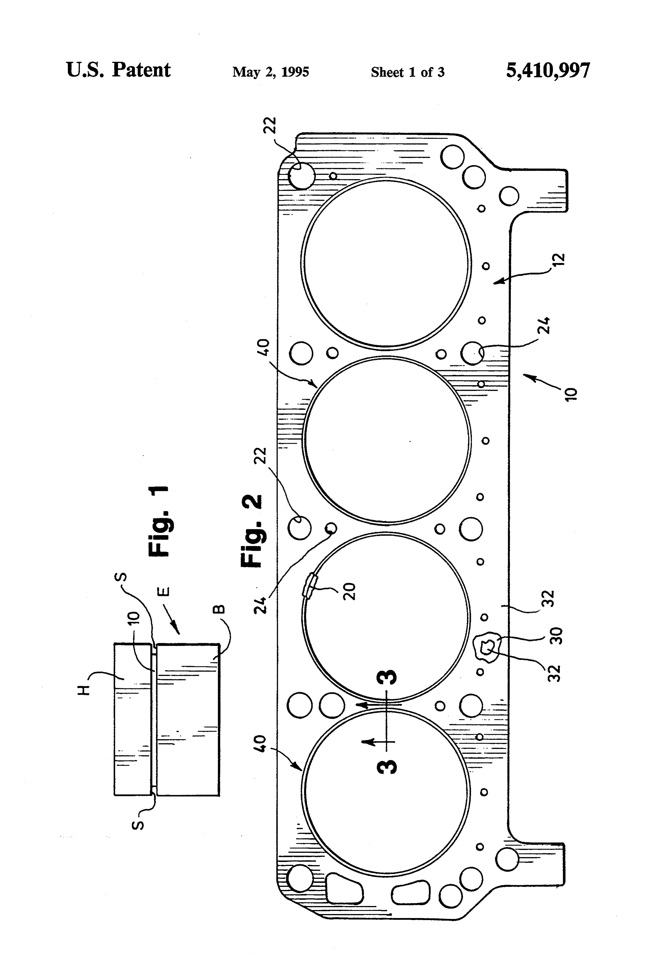
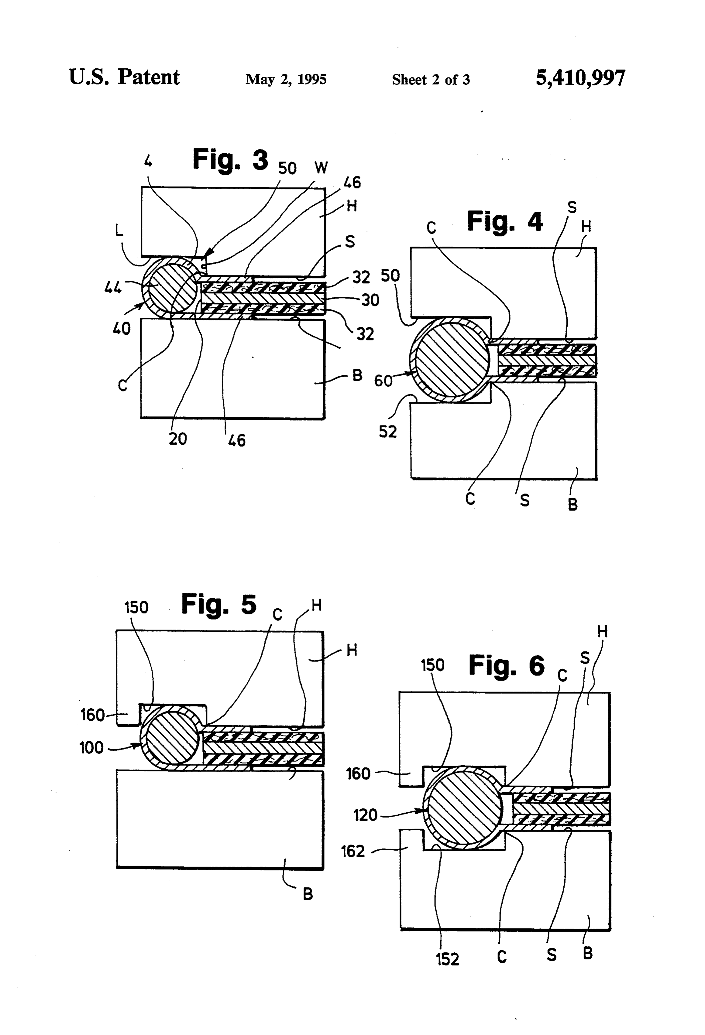
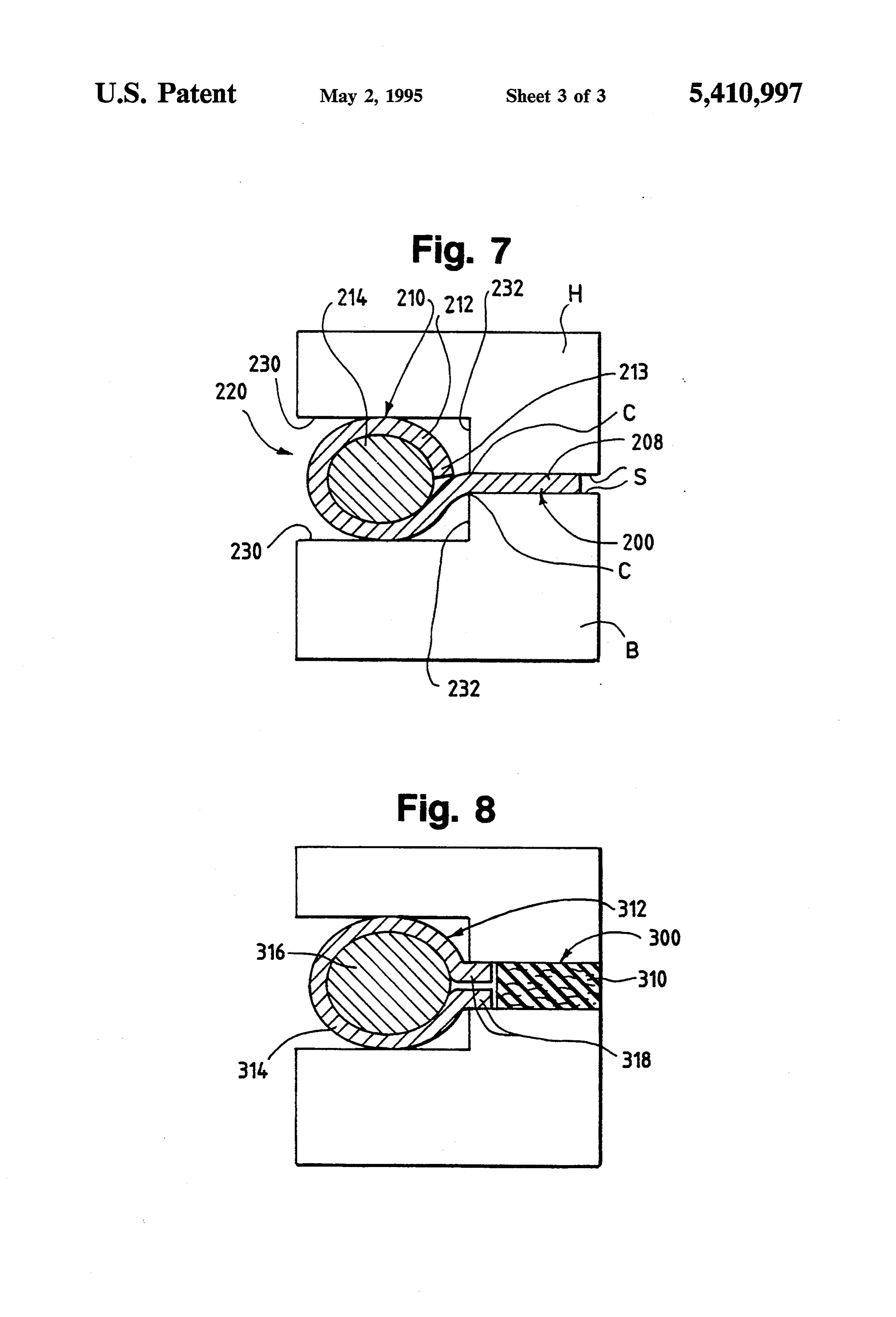
FIG. 1 is a schematic view of an automotive engine ally square or which may be slightly chamfered. The assembly in accordance with the invention disclosed in height of the groove is such that when the engine is my prior application Ser. No. 08/015,648; closed and the gasket is properly positioned, the wire FIG. 2 is a plan view of a gasket employed in the ring 44 will be significantly compressed. engine assembly of FIG. 1; From FIGS. 2 and 3 it will be apparent that when the FIG. 3 is a cross-sectional view taken substantially gasket is positioned on the block relative to the head, along line 3-3 of FIG. 2; and the gasket 10 is torqued down between clamping FIGS. 4-6 are cross-sectional views like that of FIG. surfaces S of the head and block via bolts (not shown), 3, but showing other embodiments previously disclosed; that the gasket is securely clamped into sealing engage FIG. 7 is a cross-sectional view, like that of FIG. 3, of 15 ment with the head and block and the wire ring is com an improved gasket of my present invention; and pressed. Indeed the gasket and armor produce a com FIG. 8 is a cross-sectional view of a further embodi bustion seal which has a primary seal against the land ment of an improved gasket of my present invention. area L., a secondary seal against the corner C and a DETAILED DESCRIPTION OF THE tertiary seal against the head and block in the zone of PREFERRED EMBODIMENTS the legs 46 of the armor at which the armor is clamped against the main body. The plural seals also produce a
Referring now to the drawings, an engine assembly in labyrinth effect, with any escaping gas being under accordance with my invention as disclosed in applica reduced pressure at the secondary and tertiary seals, tion Ser. No. 08/015,648, comprises an engine E (shown making sealing of those zones somewhat easier. Of schematically in FIG. 1) having a head Hand a block B. 25 course, the liquid seals are provided by the composite A gasket 10 in accordance with this invention is dis facing layers 32.
posed between them in a sealing relationship against The gasket and engine assemblies described provide their respective clamping surfaces S. combustion seals which are more effective than those The head and block define a plurality of combustion currently used and which are more convenient than cylinders as well as oil and coolant passages and bolt 30 those typically used in high performance engines. The holes via which the engine assembly is clamped. The assemblies resist pull-in, the tendency of wire to be gasket 10 defines aligned, complementary combustion pulled into the combustion cylinders under high vac openings 20, coolant and oil passages 22, and bolt holes uum under extreme conditions. Similarly, physical 24. blow-out of the armors and associated wire rings is The gasket 10 comprises a main body 12 which in 35 avoided by the groove 50 and corner C, and by-pass of cludes a central metal core 30, such as of cold rolled gases in extreme operating conditions is avoided via the steel, and facing layers 32 laminated to the surface of multiple (primary, secondary and tertiary) gas seals. metal core 30. Facing layers may be of typical fiber Enhanced sealing and interlocking can be achieved /elastomer materials, such as glass fibers or other fi by additionally grooving the clamping surface of the brous materials and may utilize nitrile, neoprene, or 40 block as illustrated by FIG. 4. In that embodiment, a polyacrylic elastomers as binders. Fillers and other block groove 52 complementary to the head groove 50 conventional ingredients may also be present. is provided. These groove portions which define a pair At each combustion opening 20, a fire ring 40 is pro of confronting spaced surfaces cooperate with a fire vided. Fire ring 40 includes an armor 42 and a wire ring ring 60 having an armor and wire ring as just described 44. Wire 44 may be of low carbon steel. Armor 42 may 45 in the same manner to provide primary and secondary be stainless steel and is generally of a U-shaped cross seals at each of the two locations, rather than at one section having a closed end, which receives and en location, thereby enhancing the sealing potential of the sheathes the wire ring 44, and a pair of legs 46 which assembly.
overlie and grip the main gasket body at the peripheries The grooves 50, 52 illustrated thus far may extend of the combustion openings 20. The legs 46 may prefer 50 inwardly to the engine cylinders. It is also possible to ably fully embrace the peripheries of the main body or recess the grooves so that they lock the armor and wire may comprise tabs, as illustrated by U.S. Pat. No. ring, not only against blow out, but against pull-in as 3,560,007, for suspending the wire ring 44 in the open well. FIGS. 5 and 6 illustrate that. Thus, it is seen in ling. FIGS. 5 and 6 that an entryway to the grooves 150, 152 Although the gasket 10 so far described employs 55 is provided which is defined in part by locking lips 160, well-known features and components, it is different 162 formed with the head or with the head and block. from most such gaskets by its use of an oversized wire The locking lips define an entryway which is substan ring 44 having a thickness or diameter which is greater tially less in vertical dimension than the distance be than the thickness of the main body 12 for a purpose to tween the confronting surfaces of the groove. The seal be described. 60 ing effects of the grooves 150, 152 with their armors The sealing system of the present invention also con 100, 120, respectively, and their functional cooperation templates the provision and use of a groove 50 in one or with the associated gasket is otherwise the same as just both of the head and block of the engine. Thus, a peri described with respect to the embodiments of FIGS. metric groove surrounding each cylinder may be ma 1-4.
chined into the clamping surface S of the head adjacent 65 Referring now to the invention of FIG. 7, a gasket and generally concentric with the combustion opening 200 comprises a main body 208 and a fire ring 210 at 20 in the main body 12 of the gasket. The groove may each combustion opening. Gasket 200 may be config be variously configured, but it defines a recess in the ured generally as shown in FIG. 2, except that the en
Page 7
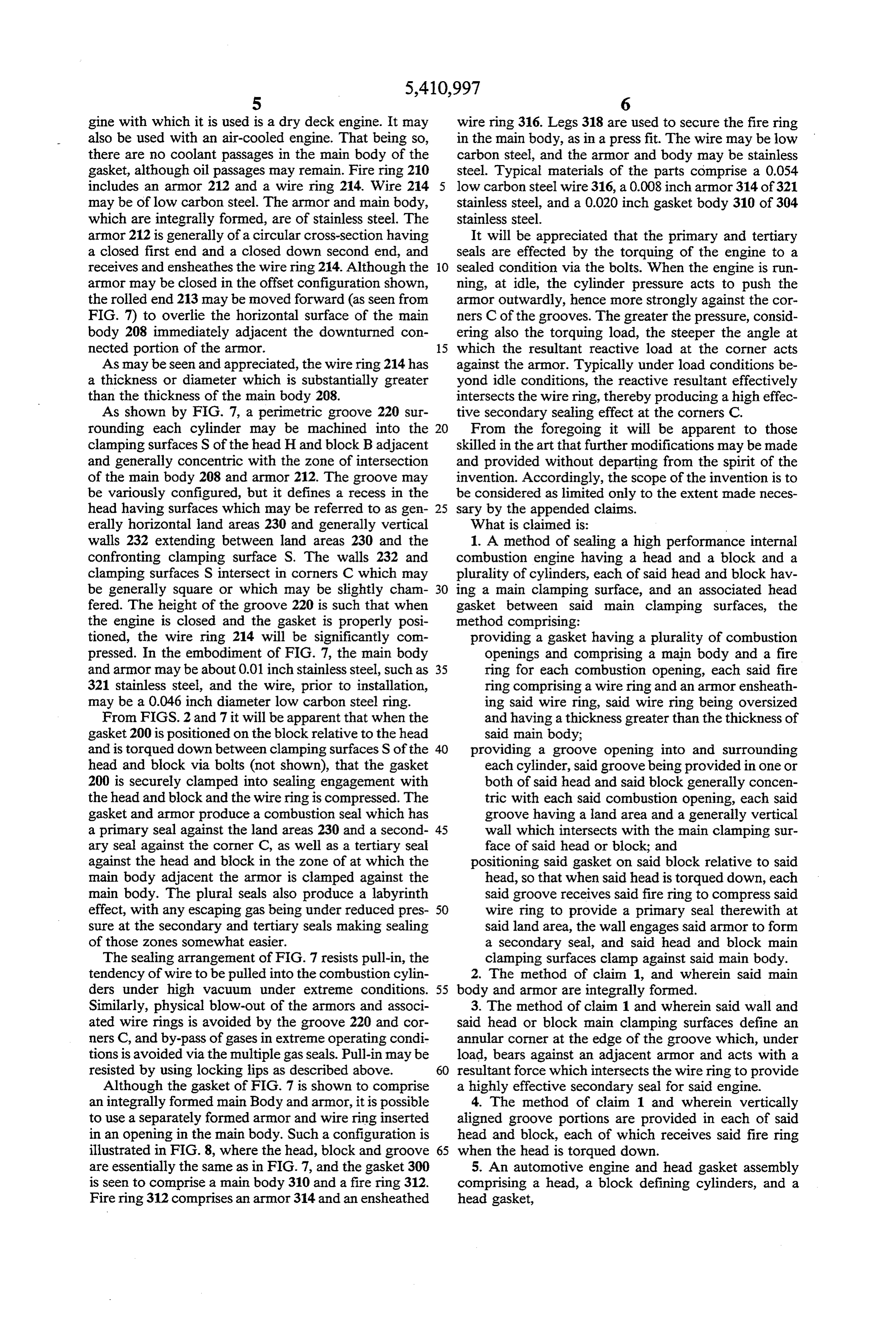
gine with which it is used is a dry deck engine. It may wire ring 316. Legs 318 are used to secure the fire ring also be used with an air-cooled engine. That being so, in the main body, as in a press fit. The wire may be low there are no coolant passages in the main body of the carbon steel, and the armor and body may be stainless gasket, although oil passages may remain. Fire ring 210 steel. Typical materials of the parts comprise a 0.054 includes an armor 212 and a wire ring 214. Wire 214 low carbon steel wire 316, a 0.008 inch armor 314 of 321 may be of low carbon steel. The armor and main body, stainless steel, and a 0.020 inch gasket body 310 of 304 which are integrally formed, are of stainless steel. The stainless steel.
armor 212 is generally of a circular cross-section having It will be appreciated that the primary and tertiary a closed first end and a closed down second end, and seals are effected by the torquing of the engine to a receives and ensheathes the wire ring 214. Although the 10 sealed condition via the bolts. When the engine is run armor may be closed in the offset configuration shown, ning, at idle, the cylinder pressure acts to push the the rolled end 213 may be moved forward (as seen from armor outwardly, hence more strongly against the cor FIG. 7) to overlie the horizontal surface of the main ners C of the grooves. The greater the pressure, consid body 208 immediately adjacent the downturned con ering also the torquing load, the steeper the angle at nected portion of the armor. 15 which the resultant reactive load at the corner acts As may be seen and appreciated, the wire ring 214 has against the armor. Typically under load conditions be a thickness or diameter which is substantially greater yond idle conditions, the reactive resultant effectively than the thickness of the main body 208. intersects the wire ring, thereby producing a high effec As shown by FIG. 7, a perimetric groove 220 sur tive secondary sealing effect at the corners C. rounding each cylinder may be machined into the From the foregoing it will be apparent to those clamping surfaces S of the head H and block Badjacent skilled in the art that further modifications may be made and generally concentric with the zone of intersection and provided without departing from the spirit of the of the main body 208 and armor 212. The groove may invention. Accordingly, the scope of the invention is to be variously configured, but it defines a recess in the be considered as limited only to the extent made neces head having surfaces which may be referred to as gen 25 sary by the appended claims.
erally horizontal land areas 230 and generally vertical What is claimed is:
walls 232 extending between land areas 230 and the 1. A method of sealing a high performance internal confronting clamping surface S. The walls 232 and combustion engine having a head and a block and a clamping surfaces S intersect in corners C which may plurality of cylinders, each of said head and block hav be generally square or which may be slightly cham ing a main clamping surface, and an associated head fered. The height of the groove 220 is such that when gasket between said main clamping surfaces, the the engine is closed and the gasket is properly posi method comprising:
tioned, the wire ring 214 will be significantly com providing a gasket having a plurality of combustion pressed. In the embodiment of FIG. 7, the main body openings and comprising a main body and a fire and armor may be about 0.01 inch stainless steel, such as 35 ring for each combustion opening, each said fire 321 stainless steel, and the wire, prior to installation, ring comprising a wire ring and an armor ensheath may be a 0.046 inch diameter low carbon steel ring. ing said wire ring, said wire ring being oversized From FIGS. 2 and 7 it will be apparent that when the and having a thickness greater than the thickness of gasket 200 is positioned on the block relative to the head said main body;
and is torqued down between clamping surfaces S of the 40 providing a groove opening into and surrounding head and block via bolts (not shown), that the gasket each cylinder, said groove being provided in one or 200 is securely clamped into sealing engagement with both of said head and said block generally concen the head and block and the wire ring is compressed. The tric with each said combustion opening, each said gasket and armor produce a combustion seal which has groove having a land area and a generally vertical a primary seal against the land areas 230 and a second 45 wall which intersects with the main clamping sur ary seal against the corner C, as well as a tertiary seal face of said head or block; and against the head and block in the zone of at which the positioning said gasket on said block relative to said main body adjacent the armor is clamped against the head, so that when said head is torqued down, each main body. The plural seals also produce a labyrinth said groove receives said fire ring to compress said effect, with any escaping gas being under reduced pres 50 wire ring to provide a primary seal therewith at sure at the secondary and tertiary seals making sealing said land area, the wall engages said armor to form of those zones somewhat easier. a secondary seal, and said head and block main The sealing arrangement of FIG. 7 resists pull-in, the clamping surfaces clamp against said main body. tendency of wire to be pulled into the combustion cylin 2. The method of claim 1, and wherein said main ders under high vacuum under extreme conditions. 55 body and armor are integrally formed.
Similarly, physical blow-out of the armors and associ 3. The method of claim 1 and wherein said wall and ated wire rings is avoided by the groove 220 and cor said head or block main clamping surfaces define an ners C, and by-pass of gases in extreme operating condi annular corner at the edge of the groove which, under tions is avoided via the multiple gas seals. Pull-in may be load, bears against an adjacent armor and acts with a resisted by using locking lips as described above. 60 resultant force which intersects the wire ring to provide Although the gasket of FIG. 7 is shown to comprise a highly effective secondary seal for said engine. an integrally formed main Body and armor, it is possible 4. The method of claim 1 and wherein vertically to use a separately formed armor and wire ring inserted aligned groove portions are provided in each of said in an opening in the main body. Such a configuration is head and block, each of which receives said fire ring illustrated in FIG. 8, where the head, block and groove 65 when the head is torqued down.
are essentially the same as in FIG. 7, and the gasket 300 5. An automotive engine and head gasket assembly is seen to comprise a main body 310 and a fire ring 312. comprising a head, a block defining cylinders, and a Fire ring 312 comprises an armor 314 and an ensheathed head gasket,
Page 8
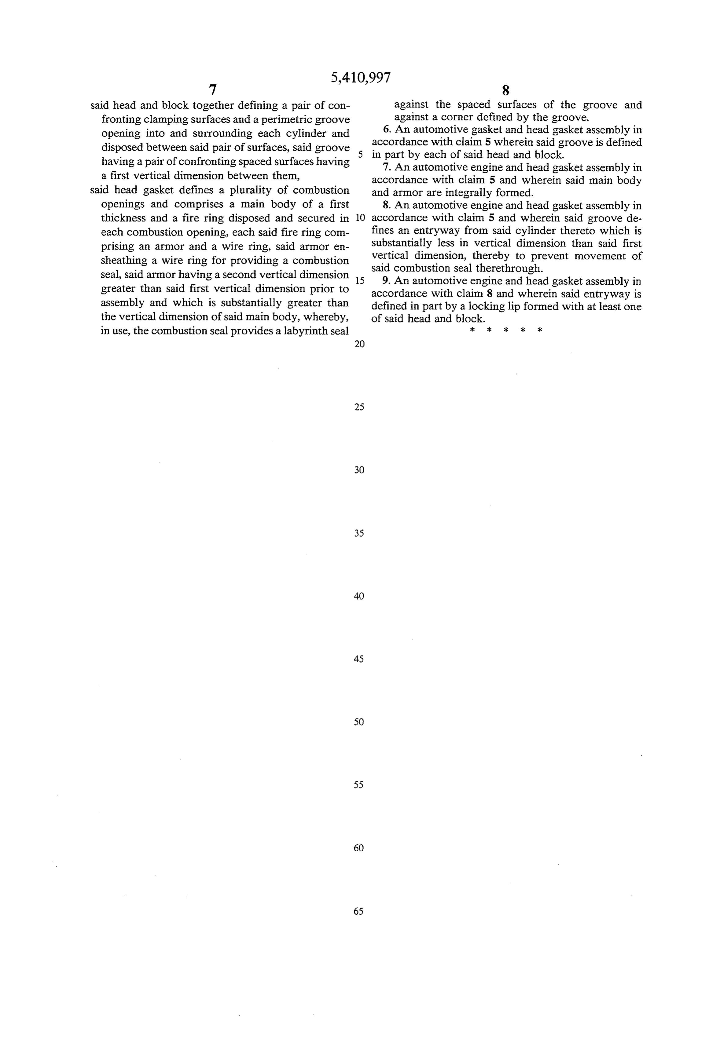
said head and block together defining a pair of con against the spaced surfaces of the groove and fronting clamping surfaces and a perimetric groove against a corner defined by the groove. opening into and surrounding each cylinder and 6. An automotive gasket and head gasket assembly in disposed between said pair of surfaces, said groove 5 accordance with claim 5 wherein said groove is defined having a pair of confronting spaced surfaces having in 7.part by each of said head and block. An automotive engine and head gasket assembly in a first vertical dimension between them, accordance with claim 5 and wherein said main body said head gasket defines a plurality of combustion and armor are integrally formed.
openings and comprises a main body of a first 8. An automotive engine and head gasket assembly in thickness and a fire ring disposed and secured in 10 accordance with claim 5 and wherein said groove de each combustion opening, each said fire ring com fines an entryway from said cylinder thereto which is prising an armor and a wire ring, said armor en Substantially less in vertical dimension than said first sheathing a wire ring for providing a combustion vertical dimension, thereby to prevent movement of Seal, said armor having a second vertical dimension 15 said9. An combustion seal therethrough.
automotive engine and head gasket assembly in greater than said first vertical dimension prior to accordance with claim 8 and wherein said entryway is assembly and which is substantially greater than defined in part by a locking lip formed with at least one the vertical dimension of said main body, whereby, of said head and block.
in use, the combustion seal provides a labyrinth seal c k ck
Provenance
- Collection
- Cited prior art
- Original PDF
- patentimages.storage.googleapis.com →
- Filed
- 1994-01-03
- Pages
- 8
- Method
- pdftotext (the PDF's own text layer) + pdftoppm 300dpi page scans
- Source
- Google Patents bibliographic record
- Granted
- 1995-05-02
- Inventors
- Gerald A. Rosenquist; Fel Pro Inc
- Transcribed from
- patentimages.storage.googleapis.com →