patent · US6093984
Rotor for electric motor
25 July 2000
Page 1 — bibliographic record
United States Patent (19) 11 Patent Number: 6,093,984 Shiga et al. (45) Date of Patent: Jul. 25, 2000 54) ROTOR FOR ELECTRIC MOTOR 5,363,003 11/1994 Harada et al. . ... 310/67 R 5,610,464 3/1997 Asano et al. ............................ 310/156 75 Inventors: Tsuyoshi Shiga, Nagoya, Kinya 5,679,997 10/1997 Matsuzawa et al. .................... 310/254 Hayashi, Toki; Masami Endou, Handa, 5,767,601 6/1998 Uchiyama ............................... 310/190 all of Japan 5,907.206 5/1999 Shiga et al. ............................. 310/156 73 Assignee: Kabushiki Kaisha Toshiba, Kawasaki,
Japan Primary Examiner Nestor Ramirez
Assistant Examiner Joseph Waks 21 Appl. No.: 09/377,742 Attorney, Agent, or Firm- Pillsbury Madison & Sutro LLP 22 Filed: Aug. 20, 1999 57 ABSTRACT 30 Foreign Application Priority Data A rotor for an electric motor includes a frame made of a resin Aug. 21, 1998 JP Japan .................................. 1O-23568O and having a cylindrical yoke mounting portion, a base (51) Int. Cl. ................................................. HO2K 1/22 covering one end Side of the yoke mounting portion, and a 52 U.S. Cl. ............................................... 310/26; 310/156 shaft Supporting portion located at the center of rotation of 58 Field of Search ..................................... 310/156, 152, the base, all of which are formed integrally with the frame, 310/154, 181, 46, 80, 103, 261; 318/41 a rotor yoke mounted on the yoke mounting portion and Substantially divided into a plurality of unit yokes, and a 56) References Cited plurality of rotor magnets mounted on the yoke mounting portion along the rotor yoke.
5,343,104 8/1994 Takahashi et al. ........................ 310/90 17 Claims, 13 Drawing Sheets
Page 2
Drawing sheet — no readable text.
Page 3
Drawing sheet — no readable text.
Page 4
Drawing sheet — no readable text.
Page 5
Drawing sheet — no readable text.
Page 6
Drawing sheet — no readable text.
Page 7
Drawing sheet — no readable text.
Page 8
Drawing sheet — no readable text.
Page 9
Drawing sheet — no readable text.
Page 10
Drawing sheet — no readable text.
Page 11
Drawing sheet — no readable text.
Page 12
Drawing sheet — no readable text.
Page 13
Drawing sheet — no readable text.
Page 14
Drawing sheet — no readable text.
Page 15
ROTOR FOR ELECTRIC MOTOR and shrinkage of the rotor yoke are circumferentially dis persed at divided portions when the frame is molded from
BACKGROUND OF THE INVENTION the resin. Since this reduces an amount of StreSS exerted on 1. Field of the Invention the base of the frame, occurrence of cracks due to the 5 residual StreSS is prevented in the base. Further, Since the
This invention relates to a rotor for electric motors, and shaft Supporting portion is prevented from displacement, the more particularly to Such a rotor provided with a frame dimensional accuracy of the Shaft Supporting portion can be molded from a resin for holding a rotor yoke on which rotor rendered stable.
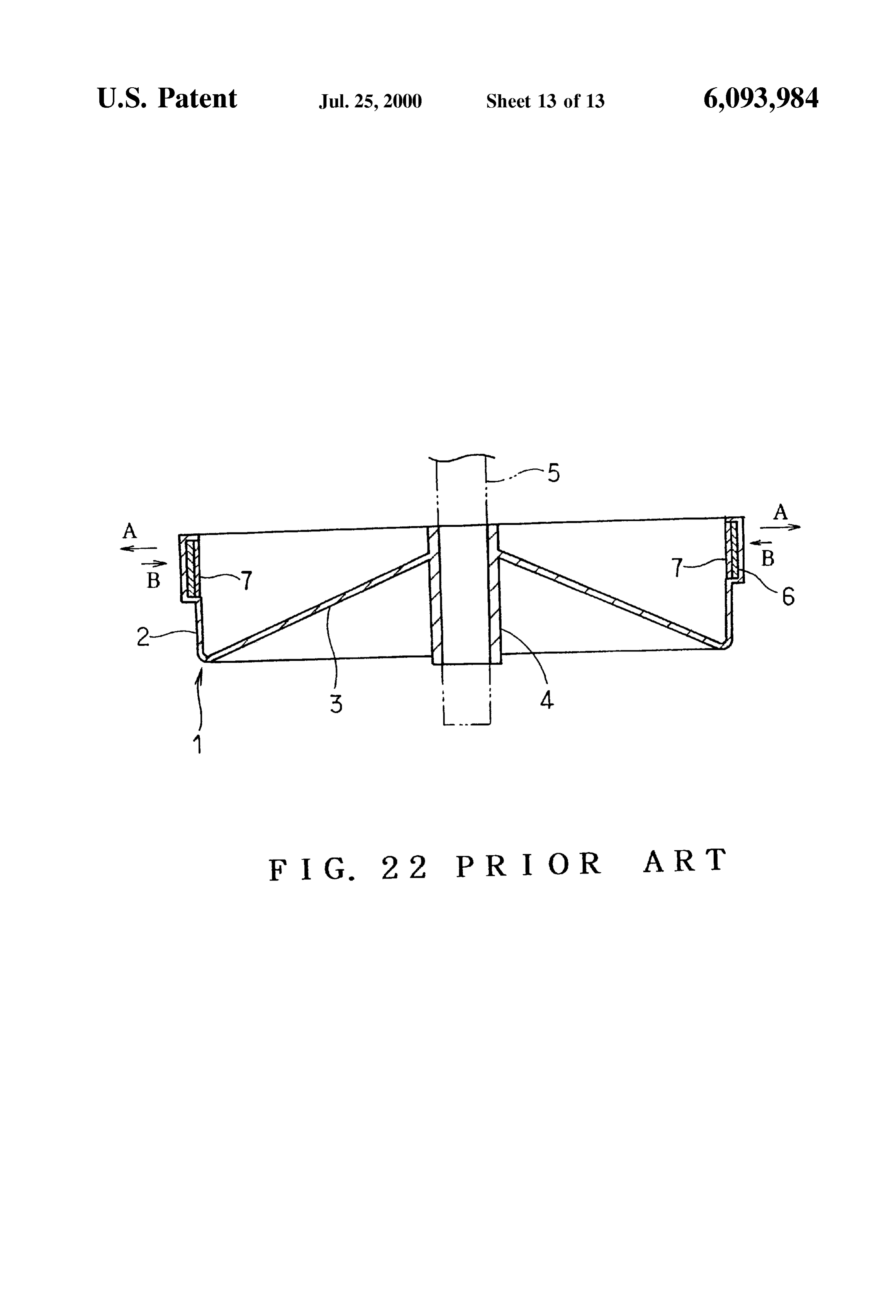
magnets are disposed. The number of the unit yokes is preferably equal to that 2. Description of the Prior Art of divisors obtained by dividing the number of teeth of a Japanese Patent Publication No. 2-211046A (1990) dis Stator by the number of phases of Stator coils, the divisors closes a rotor of the above-described type. FIG.22 shows the excluding 1. In this construction, Spaces between the adja disclosed rotor. The rotor comprises a frame 1 made of a cent ends of all the unit yokes are Simultaneously opposed Synthetic resin by way of the injection molding. The frame to the teeth of the stator or to slots defined between the teeth 1 comprises a cylindrical yoke mounting portion 2 and a 15 during rotation of the rotor. Consequently, Since the rotor base or thin sheet portion 3 having a generally V-shaped magnets develop uniform torque, nonuniformity in the rota Section. The thin sheet portion3 includes a integrally formed tion of the rotor can be reduced.
cylindrical Shaft Supporting portion 4. A rotational shaft 5 of Each unit yoke preferably has two circumferential ends the rotor is inserted through the shaft Supporting portion 4 to each of which is adjacent to each one circumferential end of be Supported. the neighboring unit yokes with a Space therebetween, and An annular rotor yoke 6 and a plurality of rotor magnets the rotor magnets preferably include those each of which has 7 are mounted on the yoke mounting portion 2. The rotor a circumferential central portion opposed to the Space yoke 6 and the rotor magnets 7 are accommodated in a between the adjacent ends of the unit yokes. Since this molding die assembly and a molten resin is then poured into construction prevents a flow of magnetic flux from being cut the die assembly so that the rotor yoke 6 and the rotor 25 or divided at the gaps between the adjacent ends of the unit magnets 7 are integrated with the frame 1. The rotor yoke 6 yokes, the magnetic property can be improved. is made by roll ingands-tacking band Steel sheets. The rotor yoke preferably has slits substantially dividing In the above-described construction, the rotor yoke 6 is it into a plurality of the unit yokes. In this construction, the Subjected heat during the injection molding of the frame 1 So unit yokes are preliminarily connected together and that the rotor yoke is deformed in the direction of arrow A accordingly, the unit yokes can readily be accommodated in FIG. 22 or in Such a direction that the diameter thereof is into a molding die.
increased. On the other hand, the diameter of the rotor yoke Each unit yoke is preferably formed by mechanically 6 is reduced in the direction of arrow B opposite arrow A connecting a plurality of axially Stacked magnetic sheets. In during the cooling of the frame 1 Subsequent to the molding. this construction, the unit yokes can be machined more As the results of these deformations and further a difference 35 easily as compared with a case where thick magnetic plates between heat shrinkage rates of the rotor yoke 6 and the are rolled into the shape of an arc. Consequently, the frame 1, the thin sheet portion 3 is Subjected to StreSS during circularity of the rotor yoke can be improved. the cooling Subsequent to the molding, whereupon the Shaft Each magnetic sheet preferably has a connecting portion Supporting portion 4 is axially deformed. Although the opposed to a circumferential central portion of the rotor molding die assembly is designed So as to cope with the magnet. Consequently, flows of magnetic flux can be pre deformation of the Shaft Supporting portion 4, the deforma vented from being obstructed by the connecting portion. tion is unstable and accordingly, a Sufficient dimensional Each unit yoke preferably has two circumferential end accuracy cannot be achieved. With this, Since the StreSS faces each of which includes a plurality of divided faces and produced during the Shrinkage and expansion of the thin at least one Stepped portion. Since a contact area of the sheet portion 3 remains alive, cracks etc. tend to occur. circumferential end faces of each unit yoke with the frame SUMMARY OF THE INVENTION is increased, a mechanical Strength of the rotor yoke can be improved.
Therefore, an object of the present invention is to provide Each unit yoke preferably has two circumferential ends a rotor for electric motors, in which occurrence of cracks can 50 each of which is formed with a notch having an open axial be prevented from being produced in the frame body and the end and an open circumferential end. Each unit yoke is held dimensional accuracy of the shaft Supporting portion can be at the notches by a pair of jigs to be accommodated into the rendered stable. molding die. Consequently, the unit yokes can readily be The present invention provides a rotor for an electric accommodated into the molding die.
motor, comprising a frame made of a resin and having a 55 The frame has a window through which a surface of each cylindrical yoke mounting portion, a base covering one end unit yoke is exposed outward. The molding die is provided Side of the yoke mounting portion, and a shaft Supporting with a positioning portion corresponding to the window. The portion located at the center of rotation of the base, the yoke Surface of the unit yoke is brought into contact with the mounting portion, the base and the Shaft Supporting portion positioning portion of the molding die So that the unit yoke being formed integrally with the frame, a rotor yoke pro 60 is radially positioned. Consequently, Since the positional Vided on the yoke mounting portion and Substantially relation between the molding die and the unit yokes is divided into a plurality of unit yokes, and a plurality of rotor rendered Stable, the circularity of the rotor yoke can be magnets provided on the yoke mounting portion along the improved.
rotor yoke. Each magnetic Sheet preferably includes an outer larger According to the above-described rotor, the rotor yoke is 65 diameter portion having a larger outer diameter than the divided into a plurality of the unit yokes completely or other outer circumferential face thereof, and the magnetic incompletely, for example, by Slits. Accordingly, expansion sheets are caulked at the outer larger diameter portions.
Page 16
Consequently, magnetic paths can be Secured around FIG. 11 is a view similar to FIG. 9, showing the rotor of caulked portions. a fourth embodiment in accordance with the invention; Each magnetic sheet preferably includes an inner larger FIG. 12 is a view similar to FIG. 9, showing the rotor of diameter portion having a larger inner diameter than the a fifth embodiment in accordance with the invention; other inner circumferential face before the magnetic sheets FIG. 13 is a view similar to FIG. 9, showing the rotor of are caulked, and the magnetic sheets are preferably caulked a sixth embodiment in accordance with the invention; at the inner larger diameter portions. The inner larger FIG. 14 is a side view of a unit yoke held by jigs; diameter portions are expanded inside when the magnetic sheets are caulked at the inner larger diameter portions. FIG. 15 is a view similar to FIG. 5, showing the rotor of However, an inner circumferential face of the inner larger a Seventh embodiment in accordance with the invention; diameter portion can be prevented from projecting to the FIG. 16 is a view similar to FIG. 5, showing the rotor of inner circumferential side relative to the other portion of the an eighth embodiment in accordance with the invention; inner circumferential face. Consequently, the rotor magnets FIG. 17 is a partial plan view of a rotor yoke of the rotor can be prevented from being displaced to the inner circum of a ninth embodiment in accordance with the invention; ferential Side when mounted on the inner circumferential 15 FIG. 18 is a view similar to FIG. 17, showing the rotor Side face of the inner larger diameter portion. yoke of the rotor of a tenth embodiment in accordance with Each unit yoke preferably has two circumferential ends the invention;
each of which overlaps one of the circumferential ends of the FIG. 19 is a partially enlarged view of the rotor yoke in adjacent unit yokes. The Overlapping portions can prevent FIG. 18;
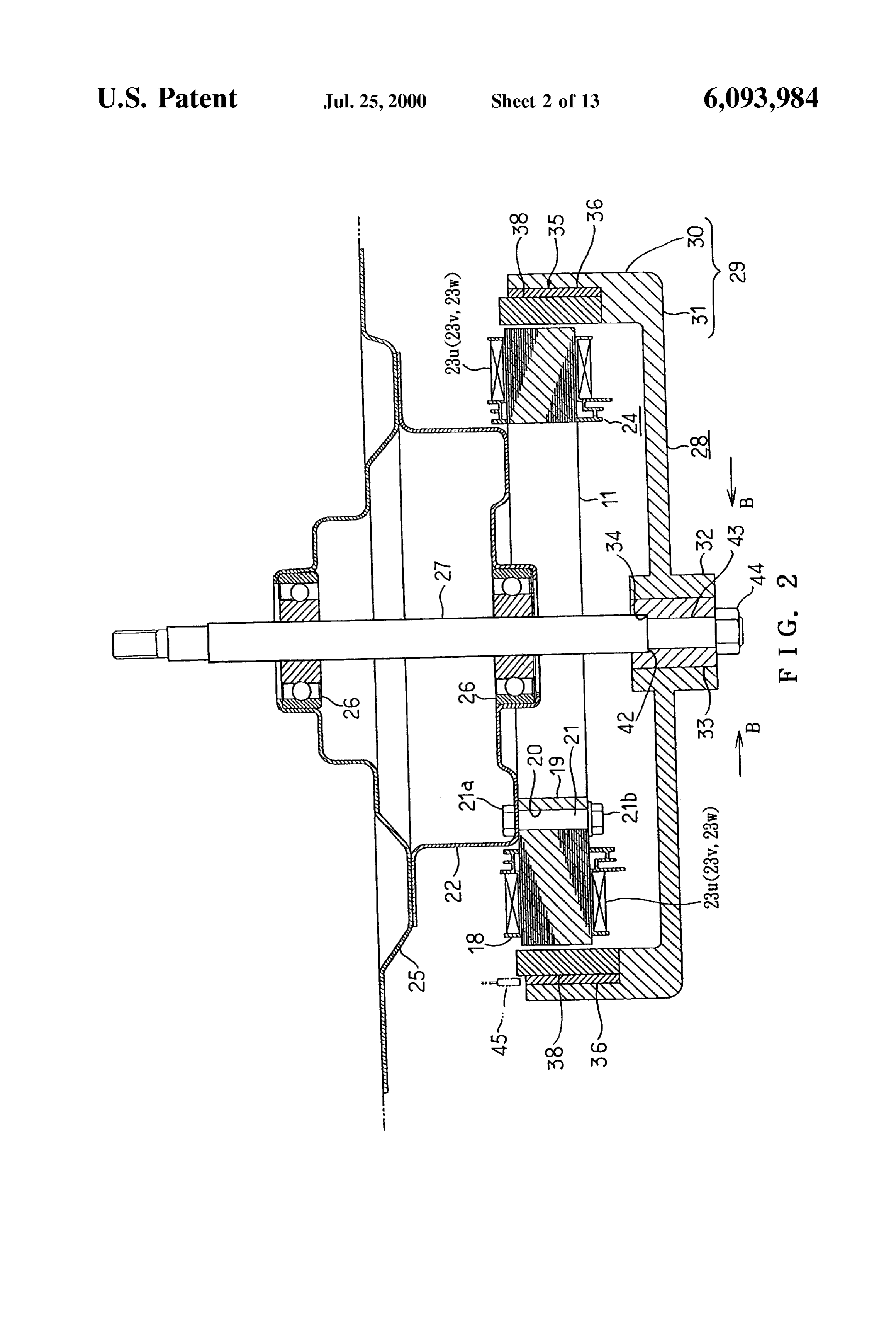
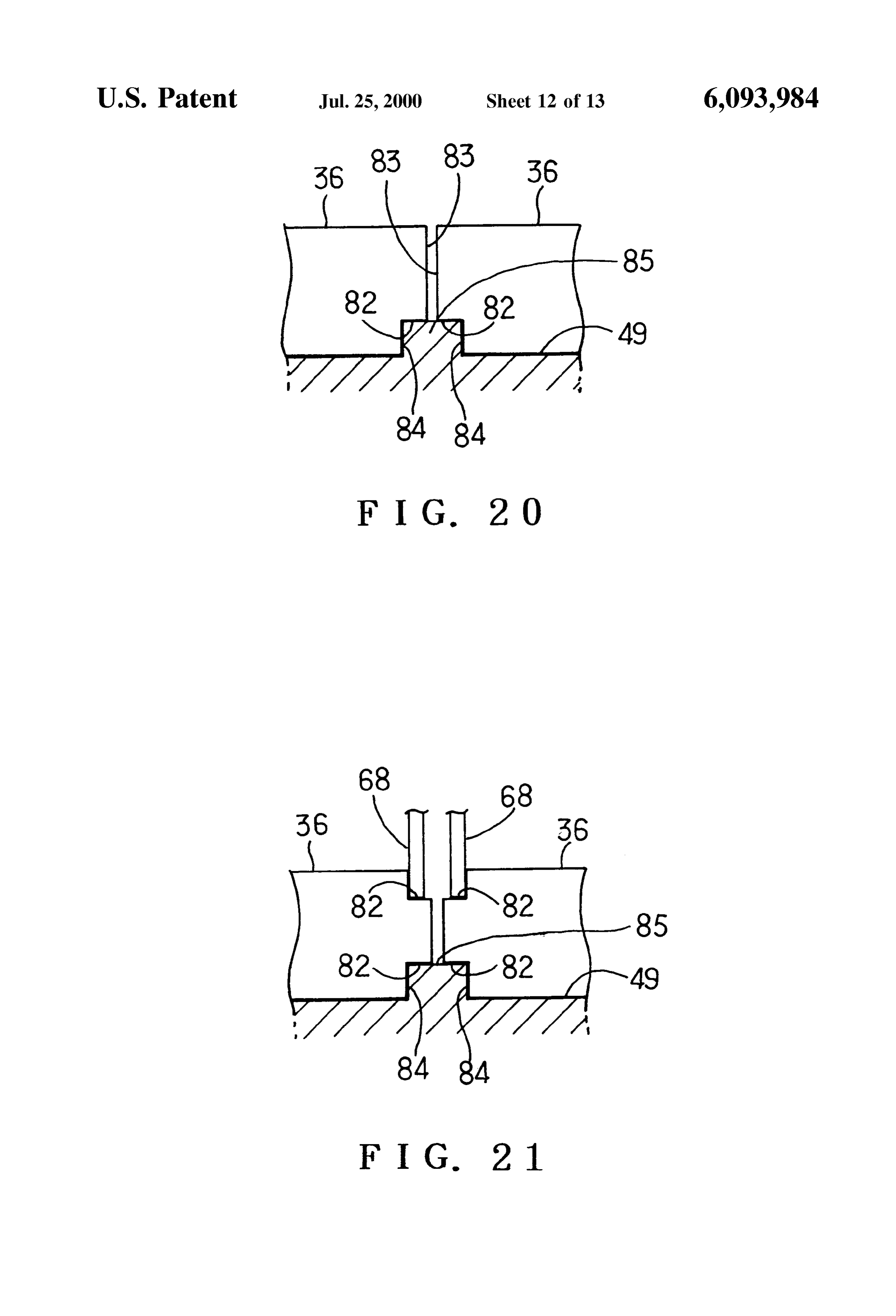
the magnetic flux from being cut or divided between the unit FIG. 20 is a partially longitudinal section of a molding yokes. fixed die accommodating the unit yokes of the rotor of an Each unit yoke preferably has two circumferential ends eleventh embodiment in accordance with the invention; formed with a convex portion and a concave portion FIG. 21 is a view similar to FIG. 20, showing a twelfth respectively, and the conveX and concave portions of each 25 embodiment in accordance with the invention; and unit yoke are preferably engaged with the concave and convex portions of the respective adjacent unit yokes when FIG. 22 is a longitudinal Section of a conventional rotor. the unit yokes are arranged in a circle So that both circum DETAILED DESCRIPTION OF THE ferential ends of each unit yoke are adjacent to the circum PREFERRED EMBODIMENTS ferential ends of the neighboring unit yokes respectively and are radially spread. When a plurality of the unit yokes are A first embodiment of the present invention will be Spread radially, each unit yoke is engaged with the circum described with reference to FIGS. 1 to 7. In the embodiment, ferentially adjacent unit yokes, So that the unit yokes are the invention is applied to a three-phase brushleSS DC motor held in the spread-diameter State. Consequently, the unit of the outer rotor type in which a rotor is disposed outside yokes in a preliminary connected State can easily be accom 35 a stator. Referring first to FIG. 3, a stator core 11 of the modated into the molding die for the frame. brushless DC motor is shown. The stator core 11 comprises Each unit yoke preferably has two circumferential ends Six unit cores 12 each of which includes an arc-shaped yoke having notches in upper or lower edges respectively. An 13 and six generally T-shaped teeth 14. Reference numeral axially open Space having a large width is formed in the ends 15 designates slots each of which is defined by the teeth 14 of the adjacent unit yokes. The circumferential end faces of 40 adjacent to each other. Each unit core 12 has two circum the unit yokes are held through the gap by a pair of jigs from ferential ends with respect to the yoke 13, the ends being the axial one end Side So that the unit yokes are accommo formed with a convex portion 16 and a concave portion 17 dated into the molding die. Consequently, the unit yokes can respectively. The convex portion 16 of each unit core 12 is readily be accommodated into the molding die. forced into the concave portion 17 of the adjacent unit core 45 12 So that the Six unit cores 12 are connected together
BRIEF DESCRIPTION OF THE DRAWINGS mechanically and magnetically. Each unit core 12 is made Other objects, features and advantages of the present by axially stacking a plurality of Steel sheets (not shown). invention will become clear upon reviewing the following A thin plate-shaped molded layer 18 molded from a description of the preferred embodiments, made with refer as shown resin synthetic is formed on the surface of the stator core 11 in FIG. 2. The stator core 11 is accommodated in ence to the accompanying drawings, in which: 50 a molding die assembly and a molten resin is then poured
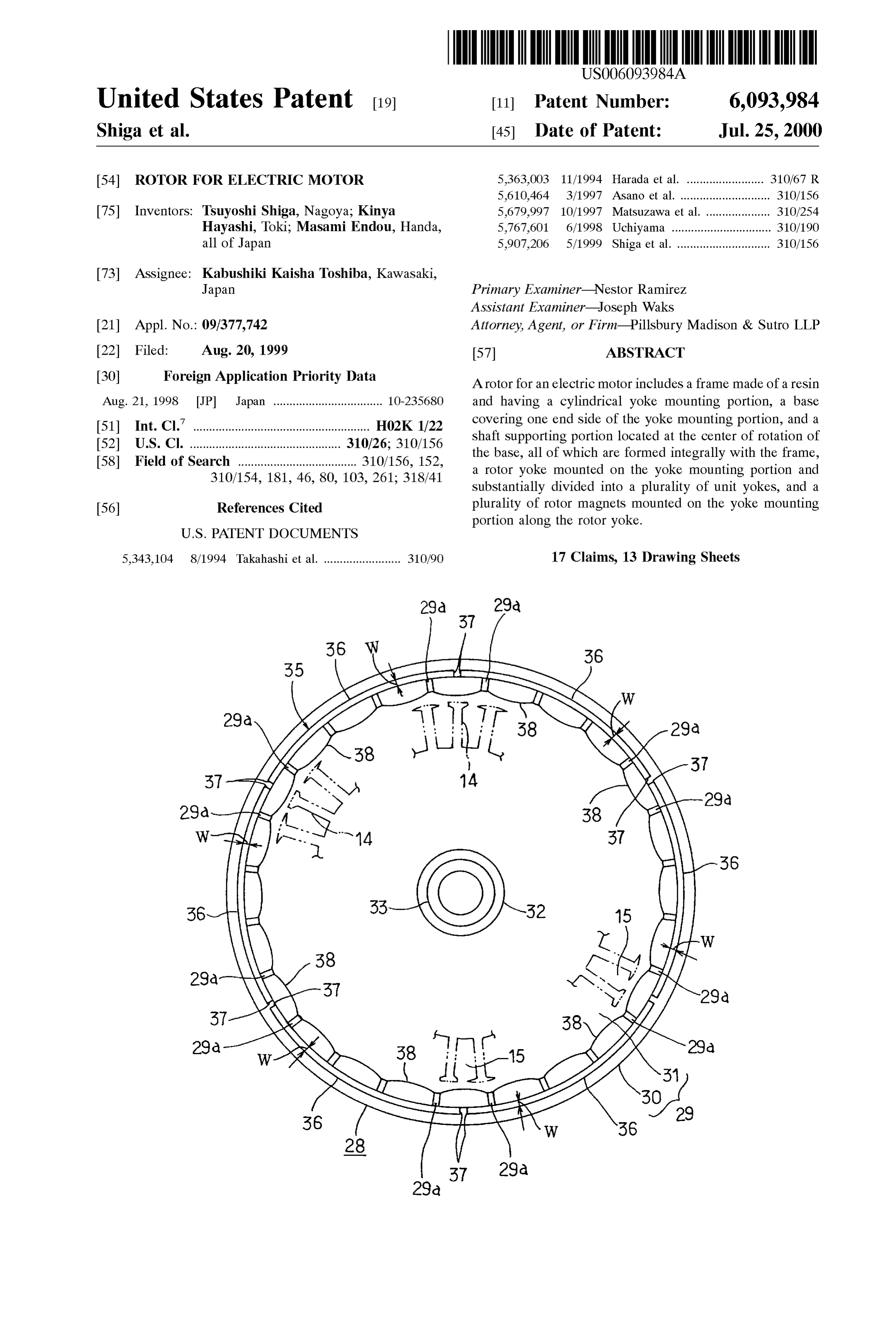
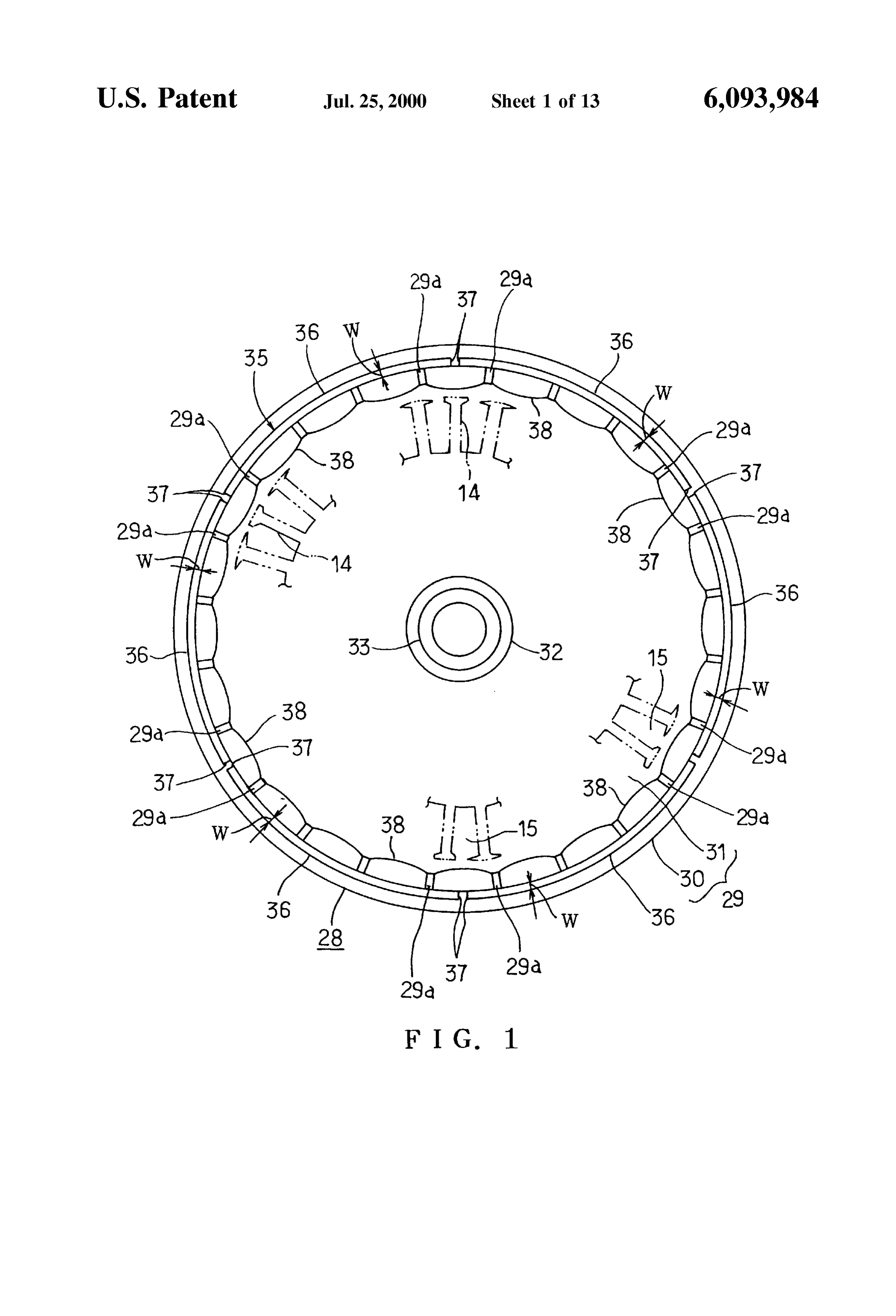
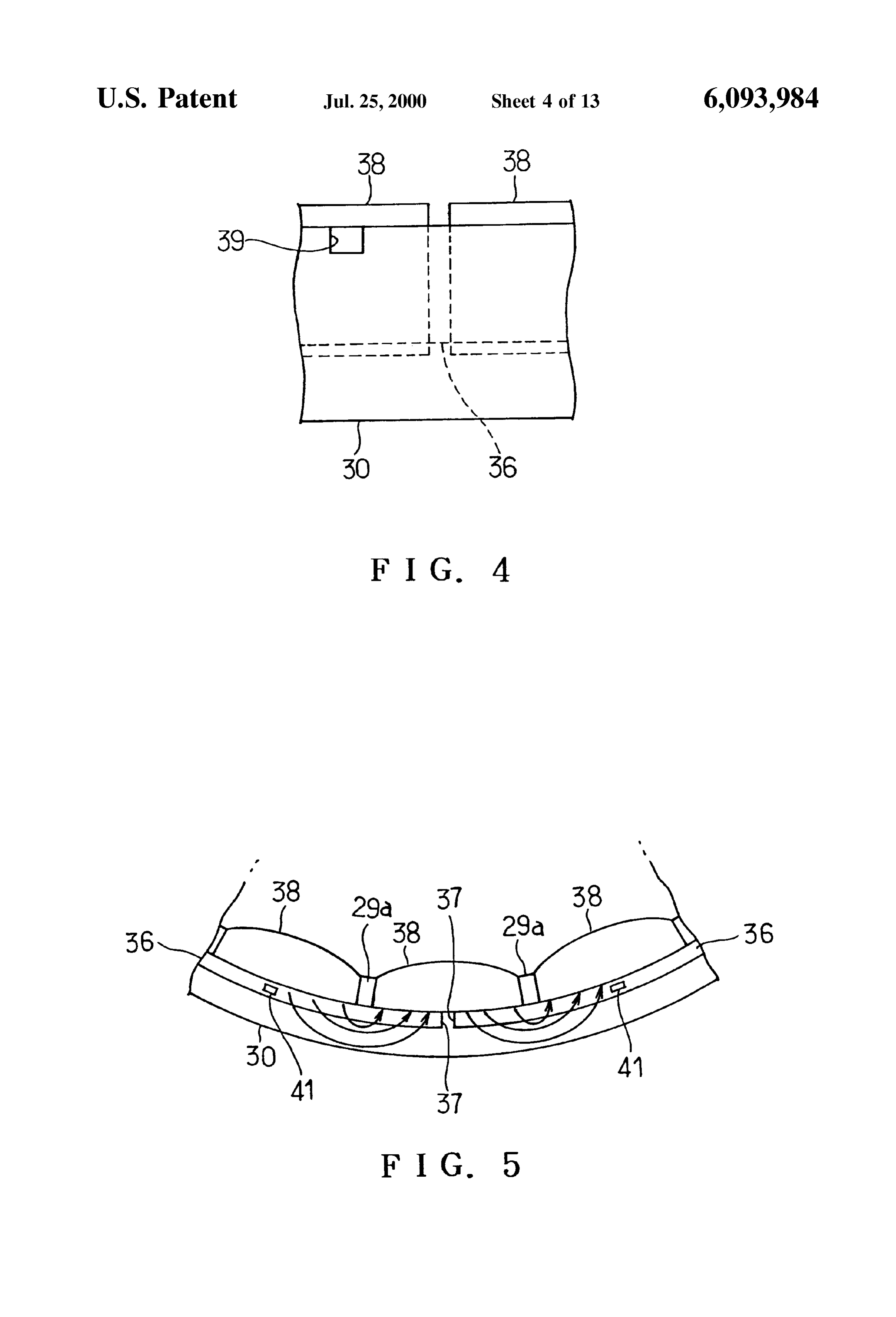
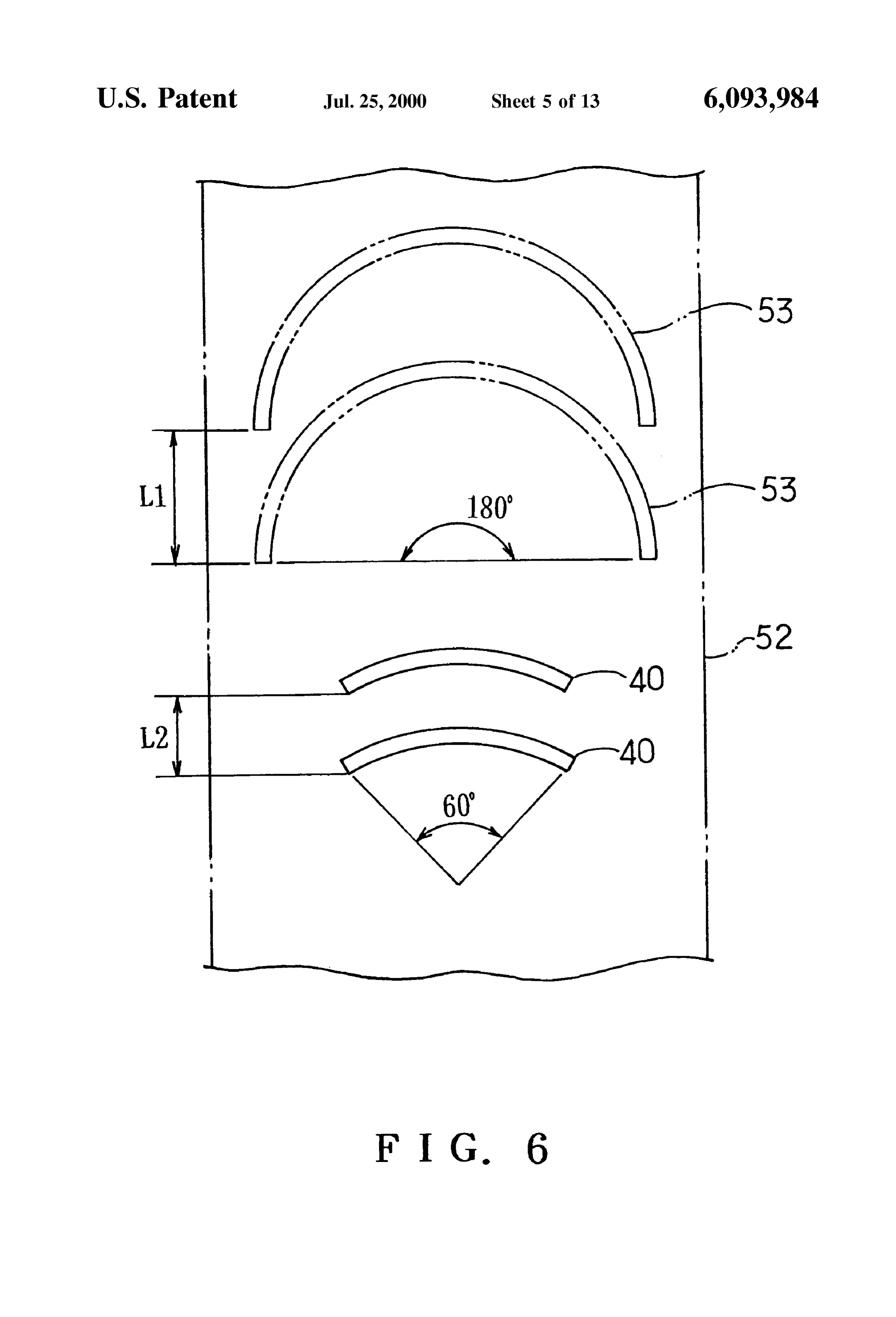
FIG. 1 is a plan view of a rotor for an electric motor of a into the die assembly so that the molded layer 18 is formed. first embodiment in accordance with the present invention; The molded layer 18 has a plurality of mounting pieces 19 FIG. 2 is a longitudinal section of the motor; integrally formed on an inner circumferential portion thereof FIG. 3 is a plan view of a stator core of the motor; 55 at equal spaces. One of the mounting pieces 19 is shown. FIG. 4 is a partially enlarged side view of the rotor; The mounting pieces 19 are formed with through holes 20 FIG. 5 is a partially enlarged plan view of the rotor; through which bolts 21 are inserted from the axially lower FIG. 6 is a plan view of a Steel sheet, explaining a endASide, first respectively.
base 22 has an upper opening and is formed into the punching manner; 60 shape of a receptacle. An upper end of each bolt 21 extends FIG. 7 is a partially longitudinal section of a die assembly through the bottom of the first base 22, projecting into the used for molding a frame; interior of the first base 22. Nuts 21a are engaged with the FIG. 8 is a view similar to FIG. 1, showing the rotor of a upper ends of the bolts 21 respectively. The mounting pieces Second embodiment in accordance with the invention; 19 and the base 22 are clamped between heads 21b of the FIG. 9 is a partial side view of a rotor yoke; 65 bolts 21 and the nuts 21a so that the stator core 11 is fixed FIG. 10 is a view similar to FIG. 9, showing the rotor of to the bottom of the base 22. Twelve phase U coils 23u, a third embodiment in accordance with the invention; twelve phase V coils 23-, and twelve phase W coils 23 ware
Page 17
S 6 mounted on the molded layer 18 further mounted on the (not shown) connected into a three-phase bridge configura stator core 11. The twelve coils per phase are formed by tion. When a PWM signal is supplied to the inverter main continuously winding a single magnet wire onto the twelve circuit for the Switching control, a driving power is Supplied teeth 14. The coils are arranged regularly in the order of the to each of the coils 23u, 23v and 23 w So that the rotor 28 is phase U, V and W coils 23u, 23v and 23 w; as shown by rotated. A Hall element 45 Serving as a magnetic Sensor is parenthesized alphabets in FIG. 3. Reference numeral 24 in disposed So as to be opposed to an axial upper end of the FIG. 2 designates a Stator 24 comprising the Stator core 11 rotor yoke 35 as shown in FIG. 2. When each rotor magnet and the coils 23u, 23 and 23 w wound on the stator core. 38 is opposed to the Hall element 45 upon rotation of the The first base 22 is fixed to a second base 25 as shown in rotor 28, the Hall element delivers a magnet detection signal. Phases of the PWM signals supplied to the respective phases
FIG. 2. Two bearings 26 have outer rings fixed to the first U, V and W are shifted on the basis of the magnet detection and Second bases 22 and 25 respectively. A rotational shaft Signal So that a Switching timing of the inverter main circuit 27 extends through inner rings of the respective bearings 26. is Set.
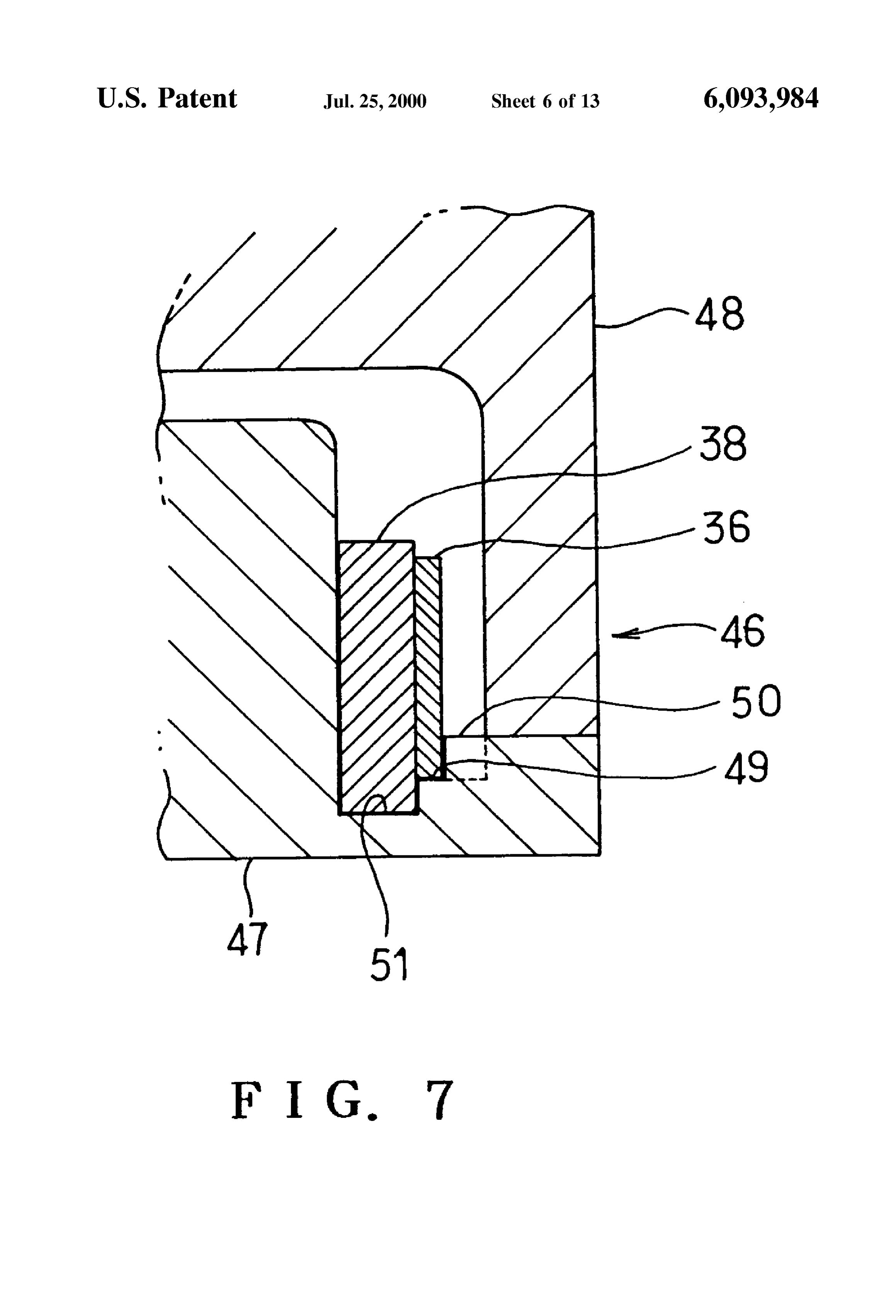
The rotational shaft 27 has a lower end to which a rotor 28 is fixed. FIG.7 shows a molding die assembly 46 used for molding 15 the frame 29. The die assembly 46 includes a fixed die 47
The rotor 28 will now be described in detail. A frame 29 and a moving die 48. The fixed contact 47 is formed with an of the rotor 28 is made of a synthetic resin by means of the annular stepped yoke setting portion 49. The unit yokes 36 injection molding and includes a cylindrical yoke mounting are Set on the yoke Setting portion 49 So as to be axially portion 30 and a flat base 31 continuous to the yoke positioned. The fixed die 47 is formed with protrusion-like mounting portion 30. The base 31 has a cylindrical resin yoke positioning portions 50 corresponding to the circum boss 32 formed integrally in the center thereof. The boss 32 ferential ends of the units yokes 36 respectively. The yoke Serves as a shaft Supporting portion. A cylindrical boSS body positioning portions 50 are provided for forming the win 33 is fitted in the boss 32. The boss body 33 is made of a dows 39 shown in FIG. 4 in the frame 29. The unit yokes 36 metal and has a stepped portion 34 formed on an inner are pressed against the yoke positioning portions 50 So as to circumferential face thereof.
25 be axially positioned. The fixed die 47 is further formed with
A cylindrical rotor yoke 35 is mounted on the yoke an annular concave magnet Setting portion 51. The rotor mounting portion 30. The rotor yoke 35 comprises six magnets 38 are axially positioned by inner and outer cir divided arc-shaped unit yokes 36 having the same radial cumferential faces and the bottom of the magnet Setting width as shown in FIG.1. Each unit yoke 36 has two straight portion 51.
circumferential end faces or divided faces 37 as shown in The procedure for manufacturing the rotor 28 will now be FIG. 5. A space is defined between the divided faces 37 described. Six unit yokes 36 are Set on the yoke Setting adjacent to each other. Twenty-four rotor magnets 38 are portion 49 of the fixed die 47, and the outer circumferential mounted on the inner circumferential face of the rotor yoke faces of the unit yokes 36 are pressed against the yoke 35 at the pitch of 15 degrees as shown in FIG. 1. The rotor positioning portions 50. Twenty-four rotor magnets 38 are magnets 38 include Six ones each of which has a circum 35 then fitted into the magnet setting portion 51 of the fixed die ferential central portion opposed to the Space between the 47 and thereafter, the moving die 48 is moved to close the divided faces 37 of the unit yokes 36 adjacent to each other. fixed die 47. A predetermined amount of molten resin is then The rotor magnets 38 are connected by connecting portions poured into the die assembly 46 so that the frame 29 is 29a formed integrally with the yoke mounting portion 30 of formed. Thereafter, the moving die 48 is moved so as to the frame 29 in a circle. An outer circumferential face of 40 open the fixed die 47, so that the frame 29 is taken out of the each rotor magnet 38 is adherent closely to the inner die assembly 46. The boss body 33 is fitted into the resin circumferential face of the unit yoke 36 so that each rotor boss 32 of the frame 29.
magnet 38 is magnetically connected to the unit yoke. According to the above-described embodiment, the rotor The yoke mounting portion 30 of the rotor 28 has rect yoke 35 is divided into the six unit yokes 36. Accordingly, angular windows 39 formed to correspond to each circum 45 expansion and shrinkage of the rotor yoke 35 are circum ferential end of each unit yoke 36 as shown in FIG. 4. A part ferentially dispersed when the frame 29 is molded from the of the outer circumferential face of the unit yoke 36 is resin. Since this reduces an amount of StreSS exerted on the exposed through each window 39. Each unit yoke 36 is base 31 of the frame 29 in the direction of rotation as shown made by stacking a plurality of steel sheets 40 (see FIG. 6) by arrow B in FIG. 2, occurrence of cracks due to the axially with respect to the rotor. The axially Stacked Steel 50 residual stress can be prevented in the base 31. Further, since sheets 40 are caulked at portions corresponding to the the resin boss 32 of the frame 29 is prevented from circumferential central portions of the rotor magnets 38 as displacement, the dimensional accuracy of the resin boSS 32 shown by reference numeral 41 in FIG. 5, so that the steel can be rendered Stable.
sheets 40 are mechanically connected together. The Steel Further, when the Space between the predetermined cir sheet 40 Serves as a magnetic sheet, and each caulked 55 cumferentially adjacent unit yokes 36 or between the portion 41 serves as a connected portion. The rotational shaft divided faces thereof is opposed to the tooth 14, all the other 27 has a Stepped portion 42 and a threaded Small diameter Spaces between the unit yokes 36 are opposed to the teeth 14 portion 43 extending from the Stepped portion. The threaded respectively, as shown by two-dot chain line in FIG. 1. portion 43 of the shaft 27 is inserted through the boss body Moreover, when the space between the predetermined unit 33 and a nut 44 is then engaged with the threaded portion 43 60 yokes 36 circumferentially adjacent to each other is opposed so that the boss body 33 is clamped between the stepped to the slot 15, all the other spaces between the unit yokes 36 portion 42 and the nut 44, whereby the rotor 28 is fixed to are opposed to the slots 15 respectively, as shown by chain the shaft 27 so as to be rotated together. line in FIG. 1. Consequently, Since a uniform torque is The phase U coils 23u, the phase V coils 23 and the developed by the respective rotor magnets 38, nonunifor phase W coils 23 ware connected via an inverter main circuit 65 mity in the rotation of the rotor 28 can be reduced and (not shown) to a direct-current power Supply (not shown). production of abnormal Sound and vibration can be pre The inverter main circuit comprises Six Switching elements vented during rotation of the rotor 28.
Page 18
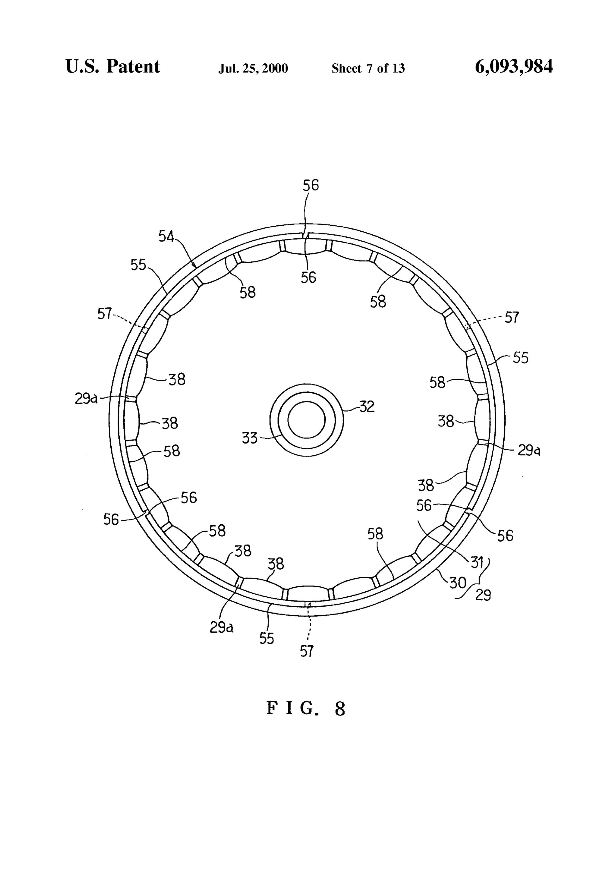
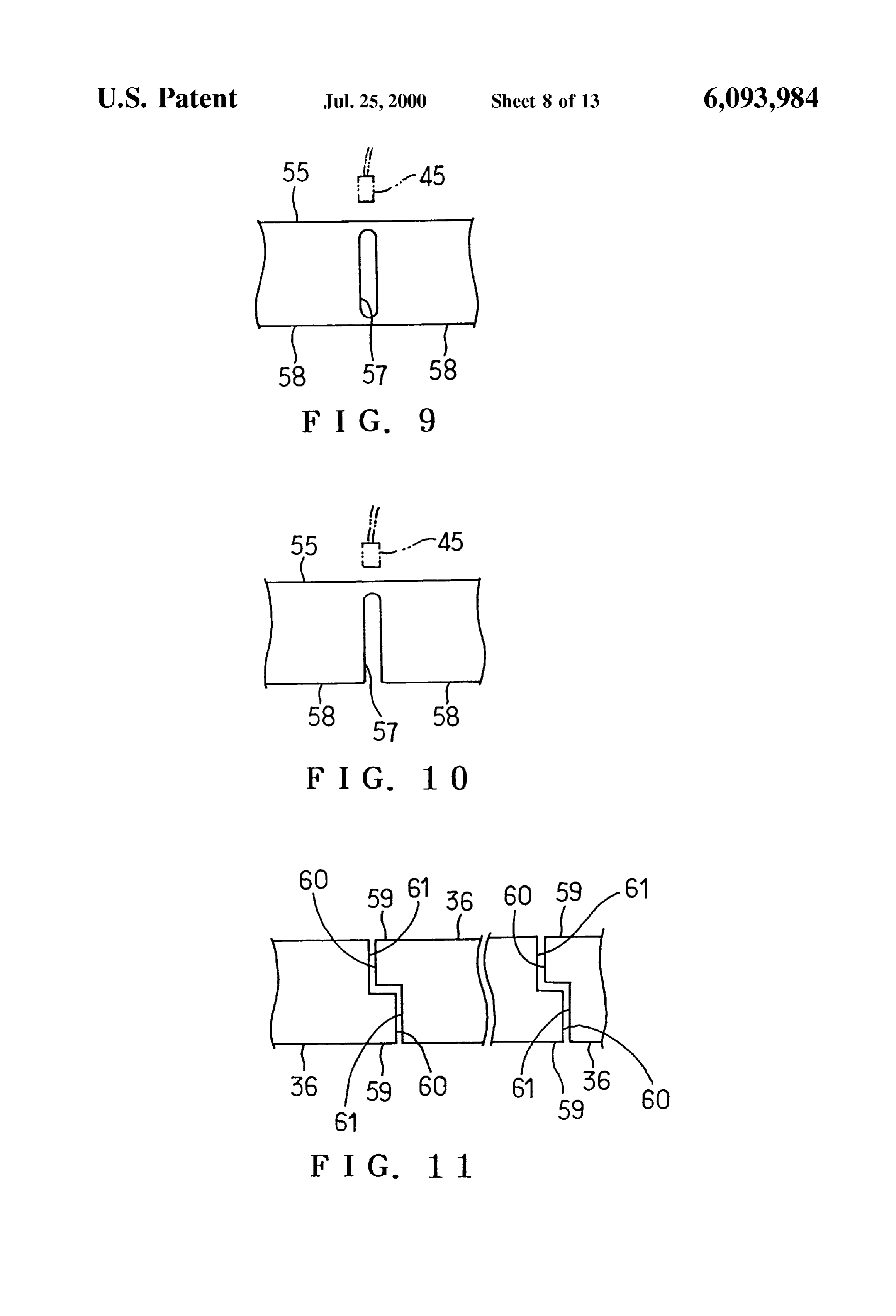
In a case where the rotor yoke 35 is divided into two unit 57 substantially divides each unit yoke 55 into two unit yokes, a punching pitch L1 between Steel sheets 53 is yokes 58 and has two closed straight axial ends. increased when the steel sheets 53 to be stacked are punched The twenty-four rotor magnets 38 are mounted on the out of a band steel 52 as shown by two-dot chain line in FIG. inner circumferential face of the rotor yoke 54 at the pitch 6. This reduces the yield of the steel sheets 53 and accord of 15 degrees as shown in FIG. 8. The rotor magnets 38 ingly increases the material cost. In the above-described include three ones each of which has a circumferential embodiment, however, the rotor yoke 35 is divided into the central portion opposed to the respective slit 57. Other three Six unit yokes 36. Consequently, Since the punching pitch L2 between the steel sheets 40 is rendered smaller, the yield can rotor opposed magnets 38 have circumferential central portions to the spaces between the unit yokes 55 or the be improved and the material cost can be Saved. Further, the divided faces 56 respectively. The three unit yokes 55 and circumferential central portion of the rotor magnet 38 is the rotor magnets 38 are accommodated into a molding die opposed to each space between the circumferentially adja cent unit yokes 36, as shown in FIG. 5. Consequently, poured assembly 46 as shown in FIG. 7 and the molten resin is magnetic paths from one rotor magnet 38 via the unit yoke the rotorintomagnetsthe die assembly 46 so that the rotor yoke 54 and 38 are integrated with the frame 29.
36 to another rotor magnet 38 are not cut or divided by the 15
Space as shown by arrows in FIG. 5 and accordingly, the According to the Second embodiment, the rotor yoke 54 magnetic property can be improved. is formed with a plurality of the slits 57 so that the rotor yoke Each unit yoke 36 is formed by axially Stacking a plurality 54
is substantially divided into a plurality of the unit yokes
Consequently, since the unit yokes 58 are mechanically of the Steel sheets 40. Accordingly, the unit yokes can be connected via the portion other than the slit 57, a plurality manufactured more easily as compared with a case where of the unit yokes thicker magnetic sheets are rolled into the Shape of an arc. into the molding58assemblyneed not be individually accommodated 46 and accordingly, the unit
Since this improves the circularity of the rotor yoke 35, mechanical nonuniformity in the rotation of the rotor 28 can yokes 58 can readily be accommodated into the molding die be reduced. Moreover, the positions of the rotor magnets 38 assembly 46.
are rendered Stable, and magnetic nonuniformity in the 25 Further, since the axial upper end of each slit 57 is closed, rotation of the rotor 28 is reduced. Consequently, production the closed upper end of each slit 57 is opposed to the Hall of abnormal Sound and vibration can be prevented during element 45 as shown in FIG. 9. The slit 57 would vary the rotation of the rotor 28. Additionally, since the axially sensitivity of the Hall element 45 if the upper end of the slit Stacked Steel sheets 40 are insulated from one another, should be open, whereupon the Switching timing of the eddy-current loSS about the magnetic flux can be prevented inverter main circuit would undesirably be shifted. In the and accordingly, the magnetic property can be improved. Second embodiment, however, this can be prevented and The axially stacked steel sheets 40 are caulked so as to be accordingly, the rotation of the rotor 28 can be Smoothed. mechanically connected together. Accordingly, the Steel Although both of the axial ends of each slit 57 are closed sheets 40 can be positioned and caulked when accommo in the Second embodiment, the axial lower end of each Slit dated into the molding die. Since this improves the circu 35 may be open and the axial upper end of each Slit may be larity of the rotor yoke 35, production of abnormal sound closed as shown as a third embodiment in FIG. 10. and vibration can be prevented during rotation of the rotor In the Second and third embodiments, a plurality of slits 28. Further, the caulked portions 41 of the axially stacked 57 may be formed in a cylindrical rotor yoke at a regular Steel sheets 40 are Set on the circumferential central portions pitch so that the rotor yoke is divided into the unit yokes the of the respective rotor magnets 38. Since the flow of the 40 number of which is equal to that of the slits 57. In this magnetic flux from one rotor magnet 38 via the unit yoke 36 construction, too, when the frame 29 is molded from the to another rotor magnet 38 is not prevented by the caulked resin, the expansion and Shrinkage of the rotor yoke tend to portions 41, as shown by arrows in FIG. 5. Consequently, be circumferentially dispersed more easily as compared with loSS in the magnetic flux by the caulked portions 41 can be a case where the cylinder yoke is formed with no slits. prevented and accordingly, the magnetic property can be 45 Consequently, occurrence of cracks due to the residual StreSS improved. can be prevented in the base 31. Further, the frame 29 is formed with the windows 39 FIG. 11 illustrates a fourth embodiment of the invention. through which the parts of the Outer circumferential faces of Each unit yoke 36 has on one circumferential end thereof a the unit yokes 36 are exposed outside. Accordingly, the unit rectangular piece or protrusion 59 located on the axial upper yokes 36 are pressed against yoke positioning portions 50 50 portion and on the other circumferential end thereof a when placed on the yoke setting portion 49 of the fixed die rectangular piece or protrusion 59 located on the axial lower 47, so that the unit yokes 36 can be positioned radially. portion. Thus, both ends of each unit yoke 36 are formed Consequently, the circularity of the rotor yoke 35 can be with circumferential steps respectively. Each protrusion 59 improved and production of abnormal Sound and vibration provides circumferential displaced straight divided faces 60 can be prevented during rotation of the rotor 28. 55 and 61 on the unit yoke 36. Spaces are defined between the FIGS. 8 and 9 illustrate a second embodiment of the circumferential opposed divided faces 60 and between cir invention. In the Second embodiment, a cylindrical rotor cumferentially divided faces 61 respectively. Spaces are yoke 54 is mounted on the yoke mounting portion 30 of the further formed between axially opposed rectangular pieces frame 29, instead of the rotor yoke 35, as shown in FIG.8. 59.
The rotor yoke 54 comprises three arc-shaped unit yokes 55. 60 According to the fourth embodiment, the circumferential Each unit yoke 55 has two straight circumferential end faces end faces of each unit yoke 36 are formed into the divided or divided faces 56. A space is defined between the divided faces 60 and 61 respectively. Consequently, Since a contact faces 56 adjacent to each other. Each unit yoke 55 is formed area between the circumferential end faces of each unit yoke by axially Stacking a plurality of Steel sheets and caulking 36 and the yoke mounting portion 30 of the frame 29 is the stacked steel sheets. Each unit yoke 55 has a slit 57 65 increased, a holding force of the yoke mounting portion 30 formed in the circumferential central portion thereof as for the unit yokes 36 can be increased and accordingly, the shown in FIG. 9 and serving as a dividing portion. The slit mechanical Strength of the rotor 28 can be improved.
Page 19
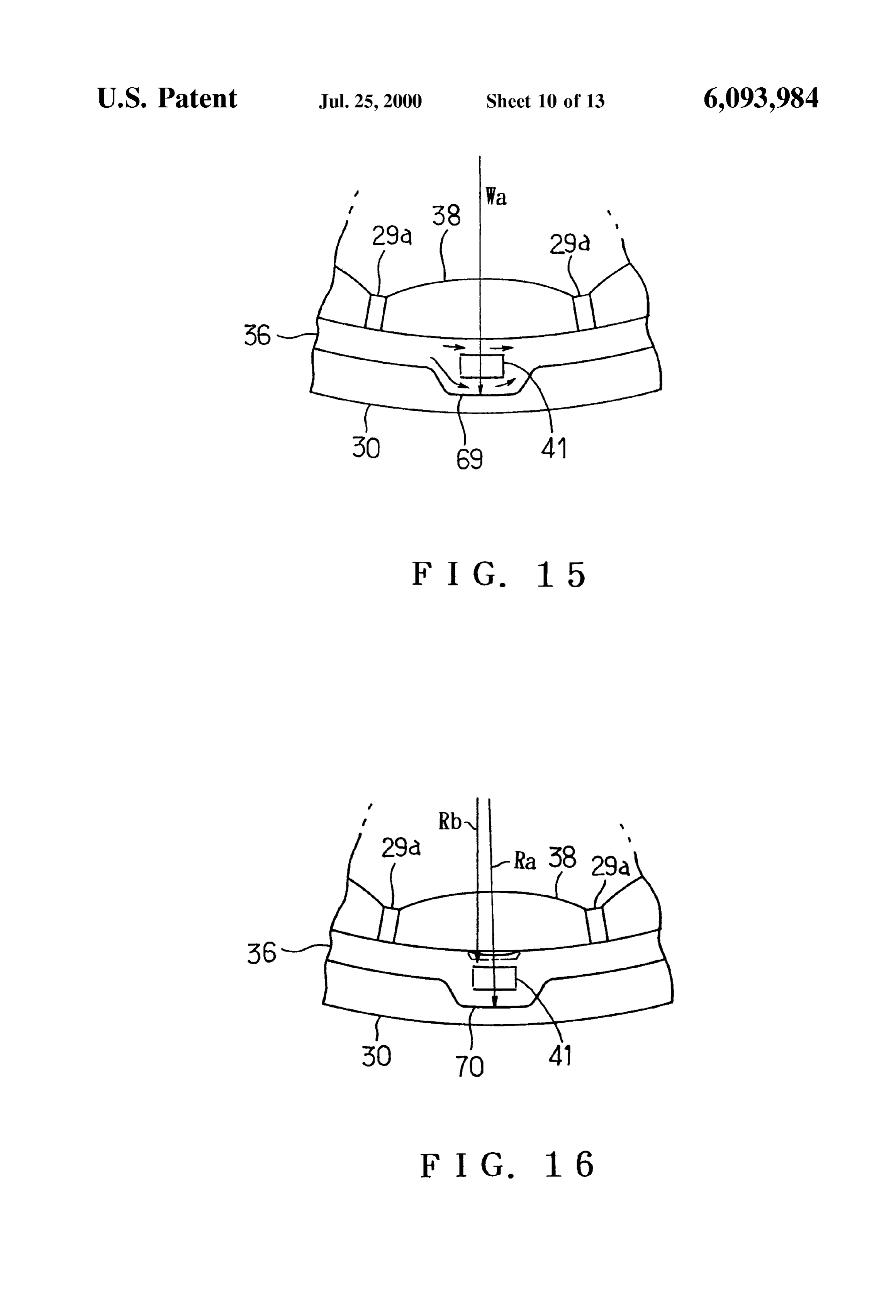
FIG. 12 illustrates a fifth embodiment of the invention. at the radially and circumferentially central portions of the One circumferential end of each unit yoke 36 has a generally wider portion 69. Reference numeral 41 designates the L-shaped engagement portion 62 located at the axial upper caulked portion.
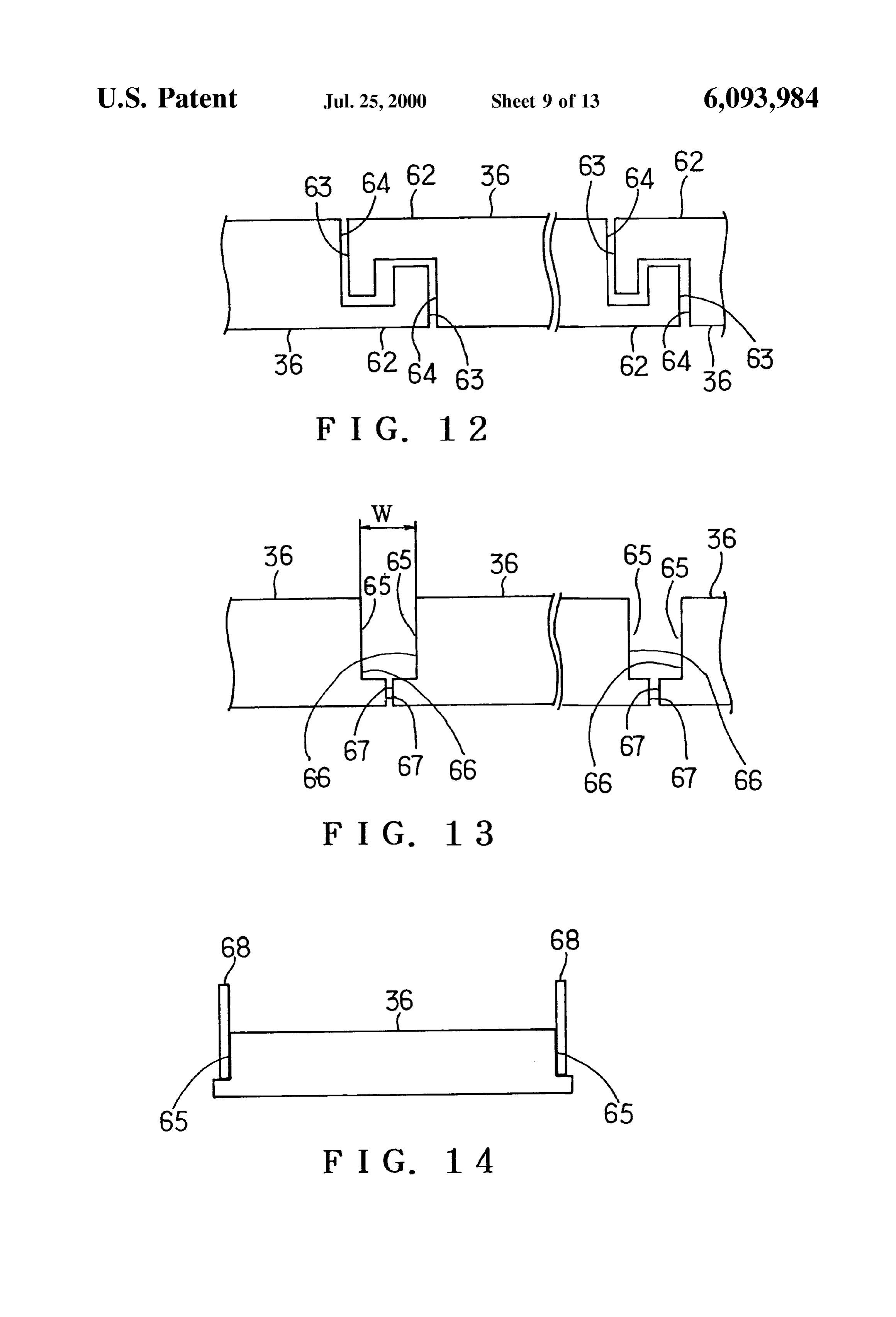
end thereof. The other circumferential end of each unit yoke According to the Seventh embodiment, each wider portion 36 also has a generally L-shaped engagement portion 62 69 enlarges the magnetic paths around the caulked portion located at the axial lower end thereof. These engagement 41 through which the magnetic flux is hard to flow. portions 62 form circumferentially displaced Straight Accordingly, Since the magnetic flux bypasses the caulked divided faces 63 and 64. Spaces are defined between the portion as shown by arrows in FIG. 15, the magnetic circumferentially opposed divided faces 63 and 64 respec property can be improved. Moreover, Since the radial width tively. Spaces are also defined between the axially opposed of the caulked portion 41 is increased, the mechanical engagement portions 62. connecting Strength of the Stacked Steel sheets 40 can be According to the fifth embodiment, the circumferential increased.
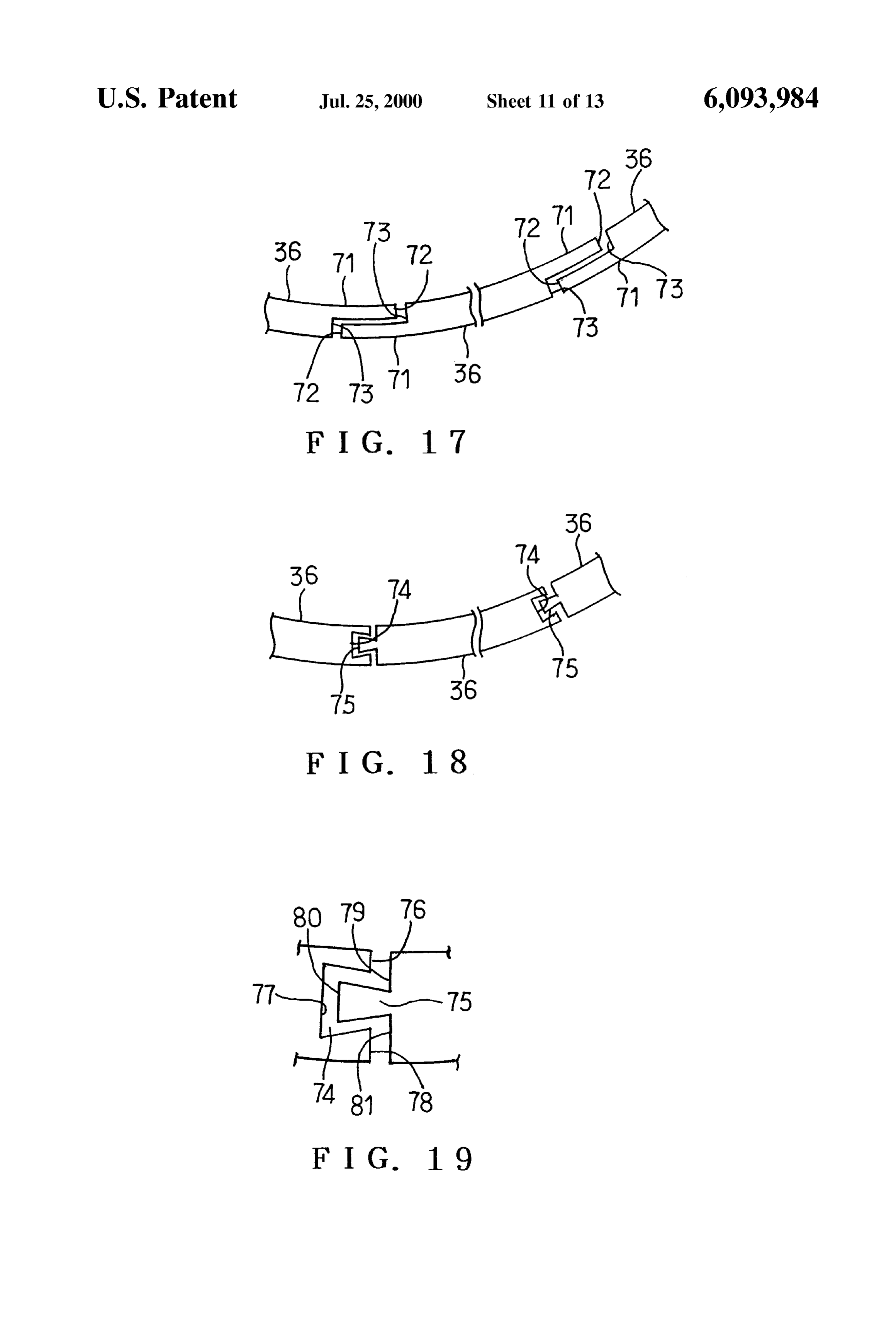
ends of each unit yoke 36 have the respective L-shaped FIG. 16 illustrates an eighth embodiment of the invention. engagement portions 62 forming the divided faces 63 and 64 Each unit yoke 36 has an inner larger-diameter portion 70 respectively. Consequently, Since the contact area between 15 formed to correspond to the circumferentially central portion the circumferential end faces of each unit yoke 36 and the of the rotor magnet 38. Each inner larger-diameter portion yoke mounting portion 30 of the frame 29 is increased, a 70 has an inner diameter Rb larger than the other inner holding force of the yoke mounting portion 30 for the unit circumferential face of each unit yoke 36 before the caulking yokes 36 can be increased and accordingly, the mechanical as shown by two-dot chain line. An Outer diameter Ra is also strength of the rotor 28 can be improved. Further, when the Set to be larger than the other Outer circumferential face. Six arc-shaped unit yokes 36 are arranged in a circle So that The stacked steel sheets 40 are caulked at the circumfer both circumferential ends of each unit yoke 36 are adjacent ential and radial central portions of each inner larger to those of the neighboring unit yokes 36 respectively and diameter portion 70, so that the caulked portion 41 is formed are radially spread, the circumferentially adjacent engage on each inner larger-diameter portion 70. AS a result, the ment portions 62 are engaged with each other, So that the Six 25 inner larger-diameter portion 70 extends to inwardly expand. unit yokes 36 are held in a spread-diameter State. However, Since the pre-caulking inner diameter Rb of the Consequently, Since the unit yokes 36 are accommodated inner larger-diameter portion 70 is Set to be larger than the into the molding die assembly 46 in a preliminarily con other inner circumferential face, the inner circumferential nected State, the working efficiency can be improved as face of the inner larger-diameter portion 70 is prevented compared with a case where the unit yokes 36 are accom from projecting inward relative to the other portion. modated into the molding die assembly 46 individually. Consequently, the rotor magnets 38 can be prevented from FIGS. 13 and 14 illustrate a sixth embodiment of the being displaced inward and accordingly, the locations of the invention. Both circumferential ends of each unit yoke 36 rotor magnets 38 can be rendered stable. Further, nonuni are formed with notches 65 having L-shaped cut ends formity in the rotation of the rotor 28 can be reduced and respectively. The notches 65 form circumferentially dis 35 production of abnormal Sound and vibration can be pre placed divided faces 66 and 67. Spaces are defined between vented during rotation of the rotor 28. the circumferentially opposed divided faces 66 and 64 FIG. 17 illustrates a ninth embodiment of the invention. respectively. A circumferential width W between the divided Both circumferential ends of each unit yoke 36 are formed faces 66 is set at a predetermined value ranging between 1 40 with inner and Outer thin Overlapped portions 71 respec to 3 mm. tively. Each overlapped portion 71 and the circumferentially FIG. 14 shows jigs 68 connected to arms of an industrial adjacent one are overlapped to form divided faces 72 and 73 robot (not shown). The circumferential end faces of the unit having a difference in level relative to each other. Spaces are yoke 36 are held by the paired jigs 68, which are then carried defined between the circumferentially opposed divided faces by the robot, so that the unit yoke 36 is placed on the yoke 45 72 and 73 respectively. Spaces are also defined between the setting portion 49. axially opposed overlapped portions 71 respectively. According to the sixth embodiment, the notches 65 are According to the ninth embodiment, each overlapped formed on the circumferential end faces of each unit yoke 36 portion 71 and the circumferentially adjacent one are over respectively. Accordingly, each jig 68 is prevented from lapped. Consequently, Since the magnetic flux is prevented interfering with the circumferentially adjacent unit yoke 36. 50 from being completely cut by the Space between the cir Further, Since the unit yokes 36 are automatically set on the cumferentially adjacent unit yokes 36, the magnetic property yoke setting portion 49 by the jigs 68, the working efficiency can be improved.
can be improved when the unit yokes 36 are accommodated FIGS. 18 and 19 illustrate a tenth embodiment of the into the molding die assembly 46. invention. One circumferential end of each unit core 36 is Although both circumferential ends of each unit yoke 36 55 formed with a trapezoidal concave portion 74, whereas the have the respective notches 65 in the sixth embodiment, only other circumferential end thereof is formed with a trapezoi one of the circumferential ends may have a notch 65. In this dal protrusion 75. The protrusions 75 are axially inserted case, the circumferential width of each notch 65 is prefer into the concave portions 74 So as to radially overlap the ably set at 2W so that each jig 68 is prevented from inner faces of the concave portions respectively. AS shown interfering with the circumferentially adjacent unit yoke 36. 60 in FIG. 19, each concave portion 74 provides circumferen FIG. 15 illustrates a seventh embodiment of the invention. tial divided faces 76 to 78 and each protrusion 75 provides Each unit yoke 36 has wider portions 69 each of which is circumferential divided faces 79 to 81. Spaces are defined formed to correspond to the circumferentially central portion between the divided faces 76 and 79, the divided faces 77 of the rotor magnet 38. Each wider portion 69 serves as an and 80 and the divided faces 78 and 81 respectively. outer larger diameter portion having an outer diameter Ra Set 65 According to the tenth embodiment, the protrusion 75 of to be larger than the other outer circumferential face of the each unit yoke 36 radially overlaps the inner face of the unit yoke 36. The axially stacked steel sheets 40 are caulked concave portion 74 of the adjacent unit yoke 36.
Page 20
Consequently, Since this prevents the magnetic flux from The metal boss body 33 is fitted into the resin boss 32 of being completely cut between the unit yokes 36 circumfer the frame 29 in the foregoing embodiments. However, the entially adjacent to each other, the magnetic property can be molten resin may be poured into the die assembly 46 with improved. Further, when the six arc-shaped unit yokes 36 the boss body 33 being accommodated in the die assembly are arranged in a circle So that both circumferential ends of so that the boss body may be integrated with the resin boss each unit yoke 36 are adjacent to those of the neighboring portion 32, for example, in stead. Further, the boss body 33 unit yokes 36 respectively and are radially spread, the may be eliminated, instead. In this case, the resin boSS 32 is protrusions 75 engage the inner faces of the concave por preferably clamped between the nut 44 and the stepped tions 74 respectively, so that the six unit yokes 36 are held portion 42 so that the rotor 28 is fixed to the shaft 27. in a spread-diameter State. Consequently, Since the unit Although the base 31 of the frame 29 is formed into the yokes 36 are accommodated into the molding die assembly flat shape in the foregoing embodiment, it may be formed So 46 in a preliminarily connected State, the working efficiency as to have a generally V-shaped Section, as shown in FIG. 21, can be improved. instead. Further, although the present invention is applied to the rotor 28 for the brushless DC motor of the outer rotor
FIG. 20 illustrates an eleventh embodiment of the inven 15type in the foregoing embodiments, the invention may be tion. Both circumferential ends of each unit yoke 36 have applied to rotors for brushless DC motors of the inner rotor rectangular notches 82 located at the lower edges thereof type in which the rotor is rotated inside the Stator. respectively. Each notch 82 provides divided faces 83 and 84 The foregoing description and drawings are merely illus having a difference in level relative to each other. Spaces are trative of the principles of the present invention and are not defined between the circumferentially opposed divided faces to be construed 83 and between the circumferentially opposed divided faces modifications willinbecome a limiting Sense. Various changes and apparent to those of ordinary skill 84 respectively. in the art. All Such changes and modifications are Seen to fall According to the eleventh embodiment, a plurality of positioning protrusions 85 are provided on the yoke Setting withinclaims.
the Scope of the invention as defined by the appended portion 49 of the fixed die 47. When the unit yokes 36 are 25 We claim:
Set on the yoke Setting portion 49, the inner faces of the 1. A rotor for an electric motor, comprising: notches 82 are brought into contact with the positioning a frame made of a resin and having a cylindrical yoke protrusions 85 so that the unit yokes 36 are circumferentially mounting portion, a base covering one end Side of the positioned. Consequently, Since the circularity of the rotor yoke mounting portion, and a shaft Supporting portion yoke 35 is improved and the nonuniformity in the rotation of located at a center of rotation of the base, the yoke the rotor 28 can be reduced, the abnormal Sound and mounting portion, the base and the Shaft Supporting Vibration can be prevented from being produced during portion being formed integrally with the frames, rotation of the rotor 28.
a rotor yoke provided on the yoke mounting portion and
The notches 82 are formed in the axially lower edges of Substantially divided into a plurality of unit yokes, and the both circumferential ends of each unit yoke 36 respec 35 a plurality of rotor magnets provided on the yoke mount tively in the eleventh embodiment. However, the notches 82 ing portion along the rotor yoke. may be formed in the upper edges of both circumferential 2. The rotor according to claim 1, wherein the number of ends of each unit yoke 36 respectively as shown as a twelfth the unit yokes embodiment in FIG. 21. In this case, a pair of jigs 68 are dividing a numberis ofequal to that of divisors obtained by inserted into the paired notches 82 located at the axially 40 of Stator coils, the divisorsofexcluding teeth a Stator by a number of phases
upper side of each unit yoke 36 So that the inner faces of the 3. The rotor according to claim 1, wherein the number of notches 82 are held by the jigs 68 respectively, whereby the the unit yokes is 3 or 6.
unit yokes 36 are set on the yoke setting portion 49.
Consequently, the working efficiency can be improved when has4.two The rotor according to claiml, wherein each unit yoke circumferential ends each of which is adjacent to a the unit yokes 36 are accommodated into the molding die 45 circumferential end of a neighboring unit yoke with a Space assembly 46. therebetween, and the rotor magnets include Some magnets The rotor yoke 35 is divided into the six unit yokes 36 in which have a circumferential central portion opposed to the the first and third to twelfth embodiments. However, the Space between the adjacent ends of the unit yokes. rotor yoke 35 may be divided into a plurality of unit yokes 5. The rotor according to claim 1, wherein the rotor yoke 36 other than six, instead. The number of unit yokes is 50 has slits substantially dividing it into the plurality of the unit preferably determined to be equal to that of divisors yokes.
obtained by dividing the number of teeth 14 of a stator by the 6. The rotor according to claim 5, which further comprises number of phases of the stator coils 23u, 23v and 23 w; the a magnetic Sensor provided at an axial end Side of the rotor divisorS eXcluding 1. yoke, and wherein each of Saids Slit has one closed axial end Each unit yoke 36 is formed by stacking a plurality of the 55 opposed to the magnetic Sensor.
steel sheets 40 in the first and third to twelfth embodiments. 7. The rotor according to claim 1, wherein each unit yoke Each unit yoke 55 is formed by stacking a plurality of the is formed by mechanically connecting a plurality of axially steel sheets in the second embodiment. However, the unit Stacked magnetic sheets.
yokes 36 or 55 may be formed by shaping a thick steel 8. The rotor according to claim 7, wherein each of said material into an arc shape, instead. 60 magnetic Sheets has a connecting portion opposed to a The axially stacked steel sheets 40 are caulked to be circumferential central portion of the rotor magnet. thereby mechanically connected together in the first and 9. The rotor according to claim 1, wherein each of said third to twelfth embodiments. The axially stacked steel unit yokes has two circumferential end faces each of which sheets are caulked to be thereby mechanically connected includes a plurality of divided faces and at least one Stepped together in the Second embodiment. However, rivets or an 65 portion.
adhesive agent may be used to connect the Steel sheets, 10. The rotor according to claim 1, wherein each of said instead. unit yokes has two circumferential ends each of which is
Page 21
formed with a notch having an open axial end and an open 15. The rotor according to claim 1, wherein each of said circumferential end. unit yokes has two circumferential ends each of which is 11. The rotor according to claim 1, wherein the frame has overlapped on one of the circumferential ends of adjacent of a window through which a Surface of each of Said unit yokes Said unit yokes.
is exposed outward. 16. The rotor according to claim 1, wherein each of Said 12. The rotor according to claim 1, wherein each of Said unit yokes has two circumferential ends formed with a unit yokes is formed by caulking a plurality of axially convex portion and a concave portion respectively, and the Stacked magnetic sheets. conveX and concave portions of each unit yoke are engaged 13. The rotor according to claim 12, wherein each of said with the concave and convex portions of respective adjacent magnetic Sheet includes a Outer larger diameter portion of Said unit yokes when the unit yokes are arranged in a having a larger outer diameter than the other outer circum circle So that both circumferential ends of each Said unit ferential face thereof, and the magnetic sheets are caulked at the outer larger diameter portions. yoke are adjacent to the circumferential ends of neighboring 14. The rotor according to claim 12, wherein each of Said unit yokes respectively and are radially spread. magnetic sheet includes an inner larger diameter portion 15 17. The rotor according to claim 1, wherein each of said having a larger inner diameter than the other inner circum unit yokes has two circumferential ends having notches in ferential face before the magnetic sheets are caulked, and the upper or lower edges respectively. magnetic sheets are caulked at the inner larger diameter portions.
Provenance
- Collection
- Cited prior art
- Original PDF
- patentimages.storage.googleapis.com →
- Filed
- 1999-08-20
- Pages
- 21
- Method
- pdftotext (the PDF's own text layer) + pdftoppm 300dpi page scans
- Source
- Google Patents bibliographic record
- Granted
- 2000-07-25
- Inventors
- Tsuyoshi Shiga; Kinya Hayashi; Masami Endou; Toshiba Corp
- Transcribed from
- patentimages.storage.googleapis.com →