patent · US4714852
Permanent-magnet field synchronous motor
22 December 1987
Page 1 — bibliographic record
United States Patent (19) 11 Patent Number: 4,714,852 Kawada et al. 45 Date of Patent: Dec. 22, 1987 (54) PERMANENT-MAGNET FIELD 3,319,100 5/1967 Erickson ............................. 310/168 SYNCHRONOUS MOTOR 3,321,652 5/1967 Opel .... ... 310/168 4,486,678 12/1984 Olson .................................. 310/156 (75) Inventors: Shigeki Kawada; Yoichi Amemiya;
Masatoyo Sogabe, all of Hachioji; FOREIGN PATENT DOCUMENTS
Kazushi Kumagai, Hino, all of Japan 50-5923 2/1975 Japan.
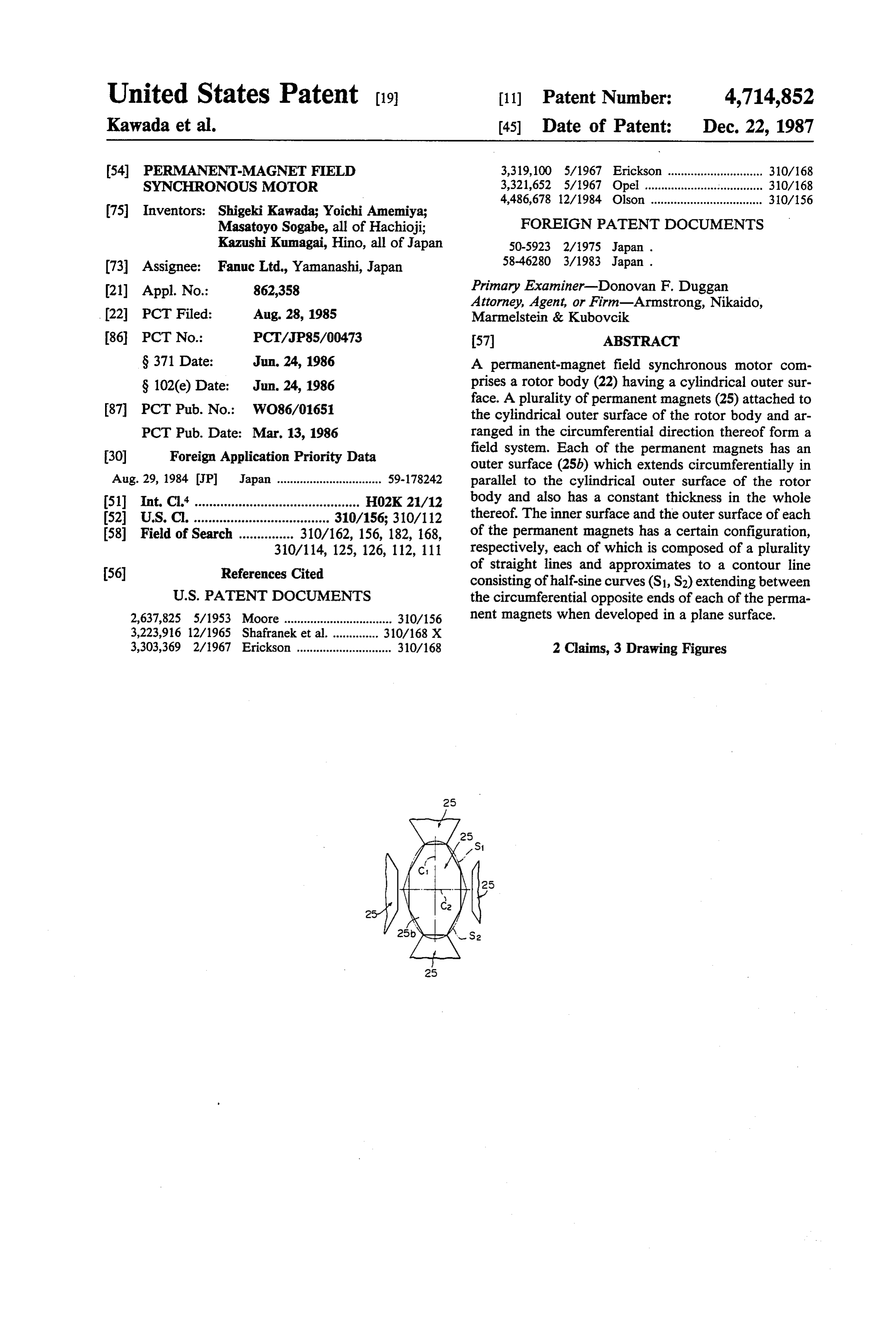
(73) Assignee: Fanuc Ltd., Yamanashi, Japan 58-46280 3/1983 Japan. 21) Appl. No.: 862,358 Primary Examiner-Donovan F. Duggan Attorney, Agent, or Firm-Armstrong, Nikaido, 22, PCT Filed: Aug. 28, 1985 Marmelstein & Kubovcik (86 PCT No.: PCT/JP85/00473 57 ABSTRACT S371 Date: Jun. 24, 1986 A permanent-magnet field synchronous motor com S 102(e) Date: Jun. 24, 1986 prises a rotor body (22) having a cylindrical outer sur face. A plurality of permanent magnets (25) attached to 87 PCT Pub. No.: WO86/01651 the cylindrical outer surface of the rotor body and ar PCT Pub. Date: Mar. 13, 1986 ranged in the circumferential direction thereof form a (30) Foreign Application Priority Data field system. Each of the permanent magnets has an outer surface (25b) which extends circumferentially in
Aug. 29, 1984 JP Japan ................................ 59-178242 parallel to the cylindrical outer surface of the rotor 51 Int. Cl* ............................................. HO2K 21/12 body and also has a constant thickness in the whole 52 U.S. C. ..................................... 310/156; 310/112 thereof. The inner surface and the outer surface of each 58 Field of Search ............... 310/162, 156, 182, 168, of the permanent magnets has a certain configuration, 310/114, 125, 126, 112, 111 respectively, each of which is composed of a plurality 56) References Cited of straight lines and approximates to a contour line consisting of half-sine curves (S1, S2) extending between
2,637,825 5/1953 Moore................................. 310/156 nent magnets when developed in a plane surface. 3,223,916 12/1965 Shafranek et al. 310/168 X 3,303,369 2/1967 Erickson ............................. 310/168 2 Claims, 3 Drawing Figures
Page 2
Drawing sheet — no readable text.
Page 3
time, by the use of permanent magnets having a con
PERMANENT-MAGNET FELD SYNCHRONOUS stant thickness.
MOTOR According to the present invention, there is provided a permanent-magnet field synchronous motor compris
TECHNICAL FIELD ing: a rotor body having a cylindrical outer surface; and The present invention relates to an improvement of a a plurality of permanent magnets attached to said cylin permanent-magnet field synchronous motor comprising drical outer surface of said rotor body, each of said a rotor body having a cylindrical outer surface and a permanent magnets having an outer surface which ex plurality of permanent magnets as a field system at tends circumferentially in parallel to said cylindrical tached on the outer surface of the rotor body and ar O outer surface of said rotor body and also having a con ranged in a circumferential direction thereof. stant thickness in the whole thereof, said outer surface BACKGROUND ART and an inner surface of each of said permanent magnets having a certain configuration, respectively, each of
A permanent-magnet field synchronous motor com which is composed of a plurality of straight lines and prising a rotor body having a cylindrical outer surface 15 and a plurality of permanent magnets as a field system approximates to a contour line consisting of half-sine curves extending between the circumferential opposite attached on the outer surface of the rotor body and ends of each of said permanent magnets when devel arranged in a circumferential direction thereof has been known. In this kind of motor, each of the permanent 20 oped in a plane surface.
According to the construction of the present inven magnets is magnetized so that magnetic poles are tion, although the outer surface of each of the perma formed on the inside and outside surfaces thereof, re nent magnets and the inner cylindrical surface of a sta spectively, and that the magnetic poles on the outside tor define therebetween a constant gap in the circumfer surfaces of the permanent magnets are alternately dif ferent in the circumferential direction. ential direction thereof, the width of each of the perma When using such a permanent-magnet field synchro 25 nent magnets in the axial direction thereof increases and nous motor as a servo motor, it is necessary to reduce then decreases in the circumferential direction along the fluctuation of a torque produced in the motor as much contour lines approximate to half-sine curves illustrated as possible in order to smoothly rotate a rotor assembly. in a cylindrical surface. Consequently, a characteristic of a magnetic flux density passing through the windings
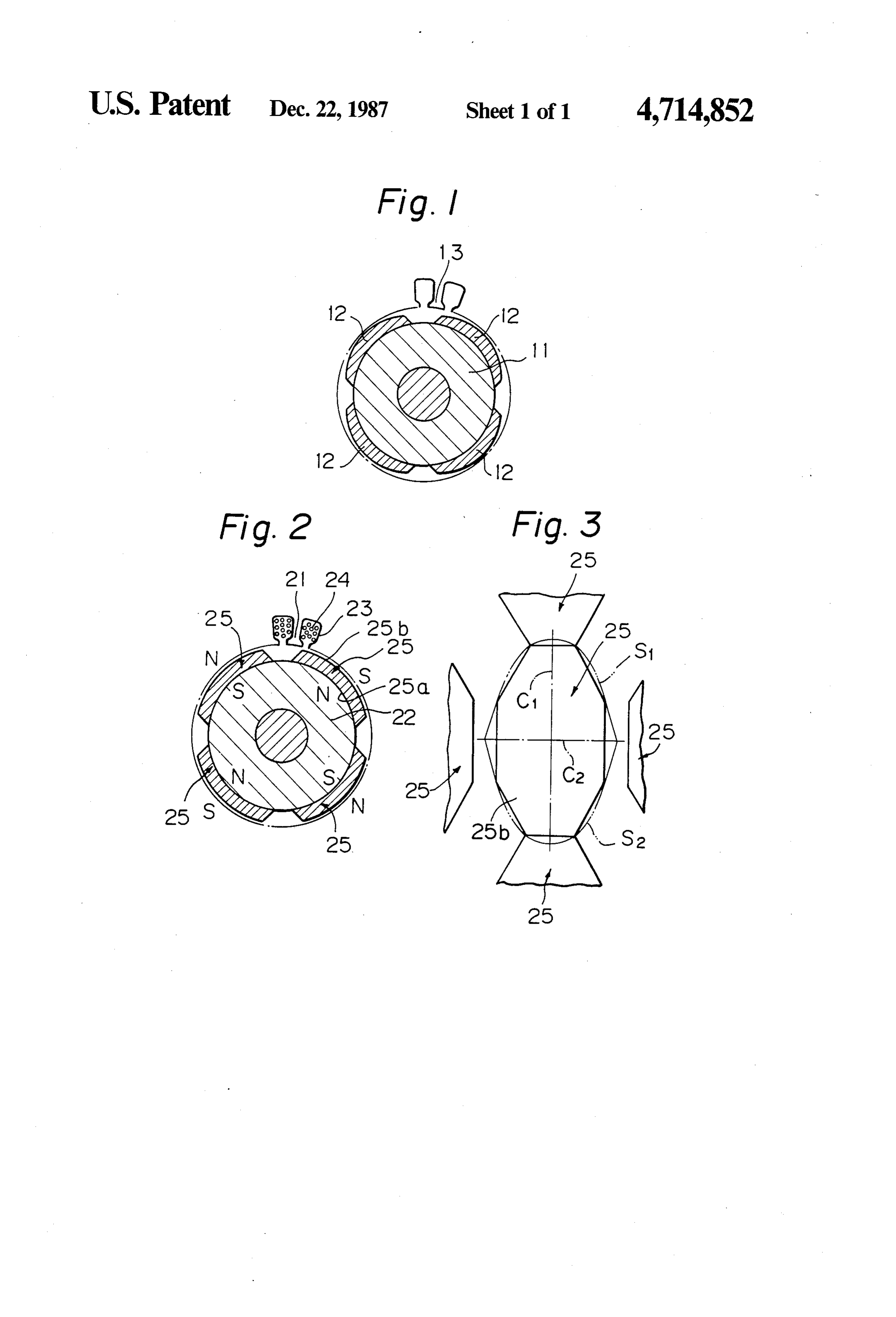
Therefore, it is desirable that a characteristic of electro motive force produced in the windings of the stator 30 of the stator changes sinusoidally in relation to time changes sinusoidally in relation to a time. For this, as while the permanent magnets as a field system rotate shown in FIG. 1, a construction in which a gap defined together with the rotor body. As a result, a fluctuation between the outside surfaces of the permanent magnets of torque produced by the motor is decreased and thus 12 fixed to the cylindrical outer surface of the rotor a smooth rotation-output is obtained. The outer surface body 11 and the cylindrical inner surface of the stator 13 35 of each of the permanent magnets extends in parallel to changes sinusoidally in accordance with rotation of the the cylindrical outer surface of the rotor body to define rotor body 11, has been adopted for a motor. a constant thickness thereof, and the configuration of In the motor having such a construction, however, each of the permanent magnets is composed of a plural since the inner surface of the stator 13 is substantially a ity of straight lines. Therefore, a press mold for the cylindrical surface, it has been necessary to give the permanent magnets can be easily made, and the outer outside surface of each of the permanent magnets 12 a surface of the permanent magnet can be easily pro specially curved shape in order to obtain such a gap cessed with a high processing accuracy. Further, since sinusoidally changeable between the cylindrical inner each of the permanent magnets has a constant thickness surface of the stator and the permanent magnets. Gener ally, the permanent magnet has been made by a press 45 in the whole thereof, a pressing force can be evenly applied to the permanent magnet. Therefore, the break sintering. When making a permanent magnet having of the permanent magnet can be prevented, and anisot such a specially curved shape, it is necessary to make a ropy in the permanent magnets can be increased. As a press mold having a specially curved concavity. There result, the magnetic property fore, processing of such a permanent magnet is difficult. can be improved, and thus theofmagnetic the permanent magnets property of the
Further, a grinding process of the outside surface of 50 such a permanent magnet, performed after molding permanent-magnet field synchronous motor can be im thereof, is also difficult. Therefore, the processing accu proved.
Preferably, the inner surface and outer surface of racy of the permanent magnet is decreased. Further more, since such a permanent magnet has a thickness each of the permanent magnets have a certain configu which becomes gradually thinner toward the opposite 55 ration, respectively, each of which configurations is ends thereof in a circumferential direction, a pressing composed of straight lines and is inscribed in or circum force tends to be applied unevenly to the permanent scribed on a virtual contour line consist of a pair of magnet, and thus an internal stress in the permanent half-sine curves extending symmetrically along the cir magnet is not uniformly distributed. Consequently, the cumferential center line of each of the permanent mag motor has a disadvantage in that the permanent magnet, nets. More preferably, the inner surface and outer sur being hard and brittle in general, is apt to be easily face of each of the permanent magnets have symmetri broken. cal configurations, respectively, in relation to the cir DISCLOSURE OF THE INVENTION cumferential and axial center lines thereof. When using such a configuration, each permanent magnet has a
An object of the present invention is to provide a 65 configuration which is substantially oval in shape, and permanent-magnet field synchronous motor in which a thus a pressing force applied to the permanent magnet characteristic of electromotive force produced in the can be more uniformly distributed during the press windings of the stator changes sinusoidally in relation to sintering thereof.
Page 4
Preferably, a plurality of permanent magnets having The permanent magnets 25 having the above the same configuration are spaced from each other in described configuration are arranged and spaced from the circumferential direction of the rotor body and each other in the circumferential direction of the rotor arranged adjacent to each other in the direction of rota body 22. The permanent magnets 25 are also arranged tion axis of the rotor body. When using such an arrange- 5 adjacent to each other in the axial direction of the rotor ment, the permanent magnets can be arranged on the body 22.
cylindrical outer surface of the rotor body with a high In the permanent-magnet field synchronous motor having the above-described construction, the configura density. Therefore, a magnetic flux density in the whole tion of the of the field system can be increased. inner and outer surfaces 25a and 25b of each The foregoing and other features and advantages of 10 straight lines somagnets of the permanent 25 is composed of a plurality the present invention will become apparent from the of that it approximates to an imaginary contour line consist of a pair of half-sine curves S1 and following detailed description with reference to the S2 when developed in a plane surface. Consequently, attached drawings.
the density of the field flux passing through the stator
BRIEF DESCRIPTION OF THE DRAWINGS 15 windings 23 is changed sinusoidally during the rotation FIG. is a schematical cross-section view illustrating of the permanent magnets 25 on the rotor body 22, a construction of the conventional permanent-magnet although magnets the outer surface of each of the permanent 25 and the cylindrical inner surface of the sta field synchronous motor; tor 21 define therebetween a constant gap in the whole FIG. 2 is a schematical cross-section view of the permanent-magnet field synchronous motor illustrating 2 thereof. Therefore, the fluctuation of the torque pro
an embodiment of the present invention; and duced by the motor is decreased, and thus a smooth FIG. 3 is a development view of the configuration of rational output of the motor is obtained. Since the inner and outer surfaces 25a and 25b of each the permanent magnet attached on the outer surface of of the permanent magnets 25 are partially cylindrical the rotor body of the motor shown in FIG. 2. 25 surfaces, respectively, a pressing mold for the perma BEST MODE FOR CARRYING OUT THE nent magnets can be easily manufactured. Further, since INVENTION the outer surface 25b of each of the permanent magnets Referring to FIGS. 2 and 3, the permanent-magnet process 25 is a partially cylindrical surface, a finish-grinding field synchronous motor comprises a stator 21 having 30 moldingcan be easily applied to the outer surface after thereof, and thus a high processing accuracy therein a cylindrical bore, and a rotor body 22 arranged can be obtained.
rotatably in the bore of the stator 21. The rotor body 22 Further, since the configuration of the inner and has a cylindrical outer surface which is arranged coaxi outer surfaces 25a and 25b of each of the permanent ally with the cylindrical inner surface of the stator 21. magnets 25 is not composed of a pair of half-sine curves The cylindrical inner surface of the stator 21 is formed 35 S1 and S2, but composed of a plurality of straight lines with slots 23 extending in the axial direction. Stator so that it approximates thereto when developed in a windings 24 are passed through the slots 23. A plurality plane surface, the configuration of the permanent mag of permanent magnets 25 forming a field system are nets 25 can be easily processed.
fixed to the cylindrical outer surface of the rotor body Furthermore, since each permanent magnet 25 has a 2. 40 constant thickness in the whole thereof, unevenness in Each permanent magnet 25 has an inner surface 25a the pressing force applied thereon does not easily occur extending circumferentially so as to fit the cylindrical during the press sintering thereof, and thus the perma outer surface of the rotor body 22, and has a constant nent magnet 25 is not easily broken. thickness in the whole thereof so that an outer surface The process of the permanent magnet 25 is accom 25b of each of the permanent magnets 25 and the cylin 45 plished in such a manner that the inner and outer sur drical inner surface of the stator 21 define therebetween faces 25a and 25b of the permanent magnet 25 are mag a constant gap. That is, the outer surface 25b of each of netized to form thereon an N or Spole after the press the permanent magnets 25 extends in parallel to the sintering and the subsequent machining of the perma outer surface of the rotor body 22. nent magnet 25 is finished. Since the pressing force is As shown in FIG. 3, the outer surface 25b of each of 50 uniformly added to the permanent magnet 25 in the the permanent magnets 25 has a configuration con thickness direction thereof, and thus the internal stress posed of a plurality of straight lines so that it approxi is uniformly distributed in the permanent magnet 25 mates to an imaginary contour line consist of a pair of during the press sintering thereof, a permanent magnet half-sine curves S1 and S2 when developed in a plane 25 having a high anisotropy can be obtained. surface. The inner surface 25a of each of the permanent 55 As a result, the strength and the magnetic characteris magnets 25 has the same configuration as that of the tics of the permanent magnet 25 can be increased. outer surface 25b thereof. Further, the configuration of Therefore, permanent magnets 25, which are expensive the inner and outer surfaces 25a and 25b of each of the in general, can be made thin and thus the cost thereof permanent magnets 25 consists of a pair of contour line can be reduced.
sections which are symmetrical to each other in relation 60 Although the foregoing explanation has been made in to a longitudinal center line C1 parallel to the rotation reference to one embodiment of the present invention, axis of the rotor body 22, and to a circumferential center the present invention is not limited to the above-men line C2 perpendicular to the longitudinal center line C1. tioned embodiment. For example, the configuration of In more detail, the configuration of the inner and the inner and outer surfaces of each of the permanent outer surfaces 25a and 25b of each of the permanent 65 magnets is not limited to and octagonal shape when magnets 25 forms, in this embodiment, and octagonal developed in a plane surface, and it may be any other shape which inscribes the above-mentioned half-sine polygonal shape, it also may be any polygonal shape curves S1 and S2 when developed in a plane surface. circumscribed with half-sine curves. Further, the per
Page 5
manent magnet may have a configuration such as ob circumferentially parallel with said cylindrical tained when the permanent magnet shown in FIG. 3 is outer surface of said rotor body, each permanent divided into two pieces along the circumferential center magnet having a polygonal shape, said polygonal line thereof. Furthermore, although the above men shape having a shape approximating that formed tioned embodiment includes a field system having four by a contour line superimposed upon said rotor poles, the present invention is not limited thereto. body, said contour line having the shape of a half CAPABILITY OF EXPLOITATION IN sine curve above a center line superimposed cir INDUSTRY cumferentially around said rotor body and said As apparent from the foregoing explanation, the per O contour line having a mirror image of the half-sine manent magnets according to the present invention can curve below the centerline, said polygonal shape be easily manufactured and the strength and the mag also being inscribed in said contour line, and netic properties of the permanent magnets can be in wherein each of said plurality of permanent mag creased. Therefore, the permanent-magnet field syn nets have the same configuration and are arranged chronous motor having excellent magnetic properties 15 and spaced from one another circumferentially can be cheaply provided. around said rotor body, and are arranged with at We claim: least one of said permanent magnets being adjacent 1. A permanent-magnet field synchronous motor to another in the axial direction of the rotor body. comprising: 2. The permanent-magnet field synchronous motor of a rotor body having a cylindrical outer surface; and 20 claim 1, wherein each of said permanent magnets is a plurality of permanent magnets attached to said symmetrical with respect to a circumferential center cylindrical outer surface of said rotor body, each of line and to an axial center line of said permanent mag said permanent magnets having a constant thick net.
ness, such that an outer surface thereof extends
Provenance
- Collection
- Cited prior art
- Original PDF
- patentimages.storage.googleapis.com →
- Filed
- 1985-08-28
- Pages
- 5
- Method
- pdftotext (the PDF's own text layer) + pdftoppm 300dpi page scans
- Source
- Google Patents bibliographic record
- Granted
- 1987-12-22
- Inventors
- Shigeki Kawada; Yoichi Amemiya; Masatoyo Sogabe; Kazushi Kumagai; Fanuc Corp
- Transcribed from
- patentimages.storage.googleapis.com →