patent · US3083311
Converters and circuits for high frequency fluorescent lighting
26 March 1963
Page 1
Drawing sheet — no readable text.
Page 2
Drawing sheet — no readable text.
Page 3
United States Patent Office 3,083,311 Patented Mar. 26, 1963
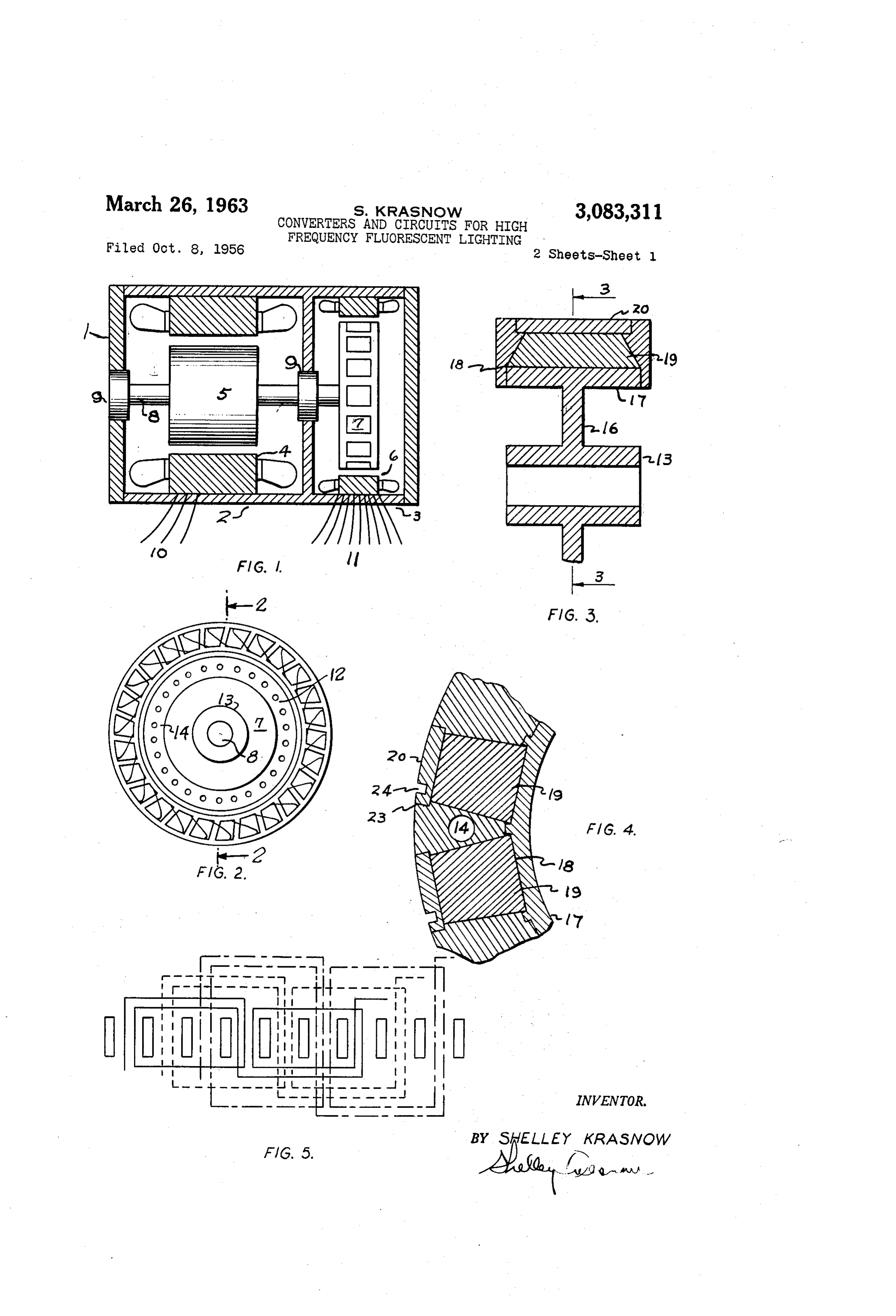
FIGURE 3 shows a cross-sectional view of the rotor 3,083,311 of the generator shown in FIGURE 2, taken across the
CONVERTERS AND CIRCUITS FOR HGH FRE plane 2-2.
QUENCY FLUORESCENT LIGHTING FIGURE 4 shows a partial cross-section of a portion Shelley Krasnow, Rte. 3, Fairfax, Va.
Filed Oct. 8, 1956, Ser. No. 614,599 of the rotor shown in FIGURE 3 taken across the plane
FIGURE 5 shows a schematic view of the armature
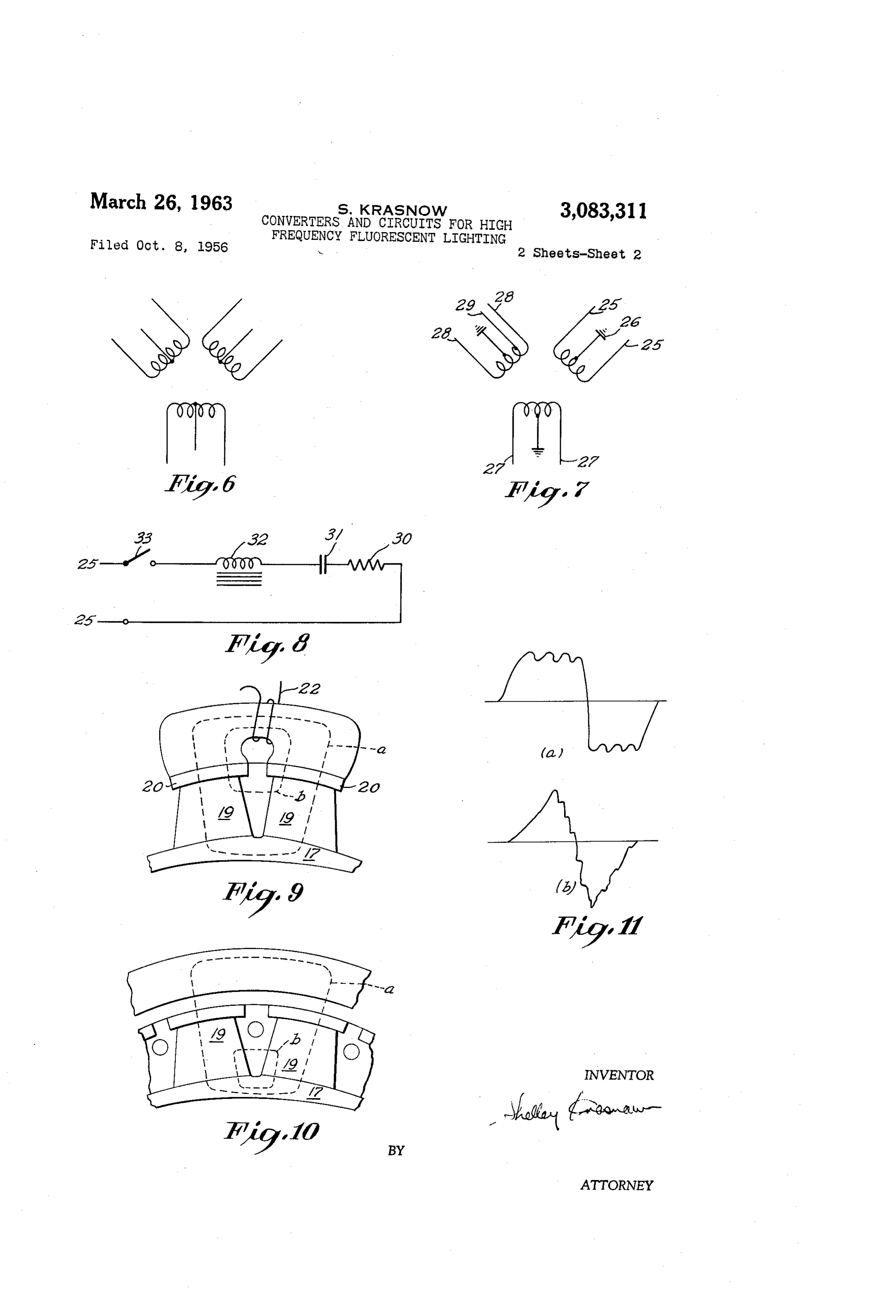
This invention relates to dynamo-electric machines and windings utilized in the generator shown in FIGURE. 2. the circuits to be used therewith. There will be de FIGURE 6 shows schematically the armature coils scribed herein a particular type of structure and a circuit 0. shown in FIGURE 5.
to be used in conjunction with such structure for high FIGURE 7 shows a wiring diagram of the armature frequency fluorescent lighting. as presented to the external circuit. Use of frequencies above 60 cycles with the conven FIGURE 8 shows a typical external circuit including tional type of fluorescent lamp has been found to yield a fluorescent lamp and its auxiliaries, suitable for con markedly superior results in operation and in life of the 5 nection to the generator shown in FIGURE 2. lamps. Frequencies of 360 and 400 cycles have been FIGURE 9 shows the method of magnetization of the used for this purpose. However, as is recognized in this magnets shown in the portion of the rotor structure pic art, frequencies above 400 cycles yield even superior tured in FIGURE 4.
results. Although the principles of construction of the FIGURE 10 shows the magnetic lines of force due to machine to be described herein and of the circuit for use 20 magnets in FIGURE 4.
therewith, will not be altered by the frequency, the par FIGURE 11 shows an oscillogram of the wave form ticular example chosen for illustration herein will be obtained with the generator shown in FIGURE 2, designed to operate at 840 cycles. Referring now particularly to FIGURE 1, 1 shows a As will be obvious to those skilled in this art, many of complete motor-generator assemblage. This consists of the features of construction of the dynamo-electric ma 25 a two-part housing, element 2 being the motor portion chine will be appropriate and applicable to other sim and 3 the generator portion. Within portion 2 is a motor ilar structures such as motors, magnetos, electrically or stator 4 and free to rotate therein, a motor rotor 5. magnetically operated clutches, servo-systems, etc. The motor may be of any of the types familiar in the It is one purpose of the invention to provide a com art. Thus it may be a direct-current type, single phase pact unitary efficient structure for the conversion of low 30 alternating current, 2 or 3 phase alternating current, etc. frequencies such as 25, 50 or 60 cycles to higher fre A preferred type for most applications will be the con quencies. ventional squirrel-cage type of 3-phase induction motor. It is a further purpose of the invention to provide a Within housing 3 is a generator stator 6 and free to ro highly efficient magnetic structure for the rotor of a tate therein, generator rotor 7. A shaft extends through dynamo-electric machine and to provide such structure 35 and is rigidly attached to rotors 5 and 7 respectively and and associated stator to deliver a wave form with a high rests in bearings 9 and 10 respectively. Connection is percentage of harmonic components, suitable for use by made to the motor for energisation thereof through leads high frequency fluorescent lighting systems. 11. The output of the generator portion is delivered It is a further purpose of the invention to provide a through leads 11. The energisation of motor 2 will cause mechanically strong rotor structure designed to withstand 40 rotation of shaft 8 and consequent rotation of rotor 7 high rotational speeds. within stator 6. This will generate electric power to be It is a further purpose of the invention to provide a delivered through leads 11.
stator structure for use in conjunction with the improved The detail of the generator portion is further shown in rotor described in order to provide a convenient means FIGURE 2. Although many of the features of the in of obtaining the desired frequency, harmonics and volt 45 vention may be attained with generators of electro age. magnetically excited types, the particular type to be de It is a further purpose of the invention to provide an scribed herein will be one utilizing permanent magnets armature winding in which the voltage stress between ad for excitation. The rotor 7 of this machine is constructed jacent conductors used therein will be reduced to a mini about a wheel-like member with an outer periphery of a mum and will thus avoid danger of breakdown. 50 ferromagnetic material. A preferred form consists of a It is a further purpose of the invention to provide an external circuit especially matched to the properties of the hub portion 13 which fits upon shaft 8, attached by means of a Web or spokes 16 to rim i7. The material of rim converter to be described so as to obtain superior results 17 may be mild or wrought steel, wrought iron, cast for the converter and circuit combination. steel or a grade of malleable iron of the general type It is a further purpose of the invention to provide a 55 known as "Magtiz.” The portions 13 and 16 need not be circuit associated with the converter to be described, of the same material, although it has been found con which will maintain a relatively constant voltage for all venient to construct the wheel portion 7 of a single cast conditions of load, without the use of any regulating ing or forging of the shape shown. Mounted upon ma equipment.
It is a further purpose of the invention to permit the 60 chined
Surfaces 18 on rim 17 are a plurality of magnets the type of construction shown, each magnet de use of a converter of the general type described in con junction with a load of high leading power factor, with fines a pole. The machine may therefore have a minimum number of 2 magnets or may have any desired larger out the necessity for complex regulating devices. number, depending upon the frequency desired and the These and other purposes of the invention will be ap 65 rotational speed to be used. In the particular example parent from the specifications taken in conjunction with shown, 28 magnets are utilized with a rotational speed the drawings in which: of 3600 rp.m., yielding 840 cycles. FIGURE 1 shows a cross-sectional view of a complete The magnets 19 are of a form different than those motor-generator frequency converter according to the heretofore used, being of frusto-pyramidal form with the invention.
FIGURE 2 shows an end view of the converter shown 70 broadest portion mounted facing the center of the rotor 7. The reasons for the selection of the form described in FIGURE 1 viewed from the generator end. will be treated further herein.
Page 4
Resting upon magnets 9 are pole pieces of ferro faces of which are machined to be in close contact with magnetic material 20. These are generally of highly the pole faces 20-20. The coil 22 serves to energize permeable material such as silicon steel and may be made horse-shoe member 2 and to cause establishment of a of a solid piece of steel or of a series of silicon steel magnetic flux therein. A high value of the direct current laminations resting edgewise upon the magnets and fas is passed through coil 22 and a high value of magnetic tened together so as to constitute an integral poie piece. flux is thereby set up in the magnetic circuit composed The pole pieces 2} are preferably made with sharply of member 2, pole faces 20, magnets 19 and rim 17. defined corners 23 and also with slots 24 cut into the It will be seen that in the magnetizing process, useful surface of the pole face. The purpose of the sharp lines of force such as (a) will pass through the entire corner 23 and the slot 24 is to introduce harmonics into structure, while non-useful or parasitic leakage lines of the generated wave. force (b) will pass through the air between magnets 19, After preliminary assembly of elements 16, 9 and 28, 19. These will not serve to magnetize the magnet and molten aluminum alloy is cast around the peripheral part in any event will not magnetize it in the direction desired. of the structure and allowed to solidify. After solidifica The closer the flanks of the magnets 19, 19, the greater tion, the rotor may be finally machined to dimension and 15 will be leakage and the greater robbing of the useful provided with balancing holes 4, between each pair of flux utilized for magnetization. The tapered form of magnets 19, 19. the magnet reduces the leakage flux by increasing the dis The magnets 19 may be made of cast Alnico magnet tance between the sides of the magnets. Magnetization material, cobalt steel, or any of the other commonly is therefore improved.
available permanent magnet materials. - 20 Superior performance during operation also results from In the specific example shown a strongly magnetic the use of the tapered magnets. Thus, as shown in FIG permanent magnet material is utilized. However, with a URE 10, the flux produced by the magnet passes through leading power factor load, such as met within a fluores pole pieces 28 and into the armature 15. However, para cent lamp and capacitor ballast arrangement, a weakly 25 sitic lines of leakage flux also exist between the magnets magnetic permanent magnet material or even ordinary and serve to reduce the total amount of the useful working steel or iron, may be used for magnets 19. flux. By tapering the magnet the distance between the Balancing of the rotor 7 to correct the inevitable mis faces is increased and the leakage factor reduced. distribution of weight therein and to prevent vibration, is A still further advantage of the tapered form, where effected by placing heavy slugs such as lead within the 30 very hard magnetic materials of the type of Alnico must balancing holes 4. be utilized, and such materials are cast, is that the tapered The conventional methods of balancing by drilling out form makes it much easier to mold and draw the castings material are not suitable for use with this structure, since from the mold.
the aluminum being a light material, will require re In operation of high frequency fluorescent lighting moval of an undue amount in order to effect balance. Systems, it has been found that the performance improves Removal of such amounts will seriously weaken the rotor 35 the higher the frequency, up to frequencies of the order structure since its strength is greatly dependent upon the of 20,000 cycles. However, as one proceeds above .400 strength of the cast aluminum. Cycles, the obtaining of substantial amounts of power The use of the tapered magnets S9 in the manner shown economically becomes more and more difficult. A prac permits the casting or drilling of larger balancing holes 40 ticable frequency, in the particular example described 14, without weakening or endangering the strength of therein is 840 cycles. However, it is desirable to have the the cast aluminum portion 2. Balancing slugs may be advantages of still higher frequencies, and this is ob placed toward either edge of the rotor 7 in order to effect tained to a considerable extent by superposing high fre dynamic as well as static balance. quency harmonics upon the fundamental 680 cycle wave. The taper of the magnets as shown has been found 45 These high frequency harmonics have been obtained in to yield Superior results in many respects. It has been the present instance by the shaping and slotting of the common in the art to provide individual magnets for the pole faces as shown in FIGURE 4, by eliminating the purpose described of parallel form such as rectangular skew in the stator structure customarily used, and by blocks or with a taper facing inwardly and having the utilizing a winding as shown in FIGURE 5. The use of larger base portion at the periphery, rather than toward 50 these expedients singly or in combination, will yield a the mounting structure of the rotor. In contradistinction, Wave form with a high percentage of harmonics as shown in the present invention, the broader portion of the mag in FIGURE 11, FIGURE 11 (a) representing the oscillo net rests against the flange. One consequence of the use gram of the Wave form at light load and FIGURE 11(b), of the tapered magnet has already been mentioned, namely the Wave form at substantial load.
making possible the enlargement of balancing hole 14. 55 It has also been found that the conducting or amortis Another advantage resides in the physical strengthening Seur bars placed customarily in the pole faces 20, may be of the rotor. After the casting of the molten aluminum, omitted with a consequent increase in the generated har during solidification thereof the aluminum will shrink. monic content.
This will cause it to exert a compressive stress inward FIGURE 5 shows the winding pattern used for the upon the elements cast therein. Since the magnets have 60 stator tapered sides, the result of this stress will be to press the have 846 ofslots.
the generator. The stator may, for example,
The winding pattern for each of the in magnets more tightly against the rim 17 and thus hold dependent phases is shown. It will be seen that each coil -the magnet in tight magnetic contact with said rim 7. Spains three slots and that the coil sides for adjacent coils The centrifugal stress on the magnet due to rotation of the rotor will be resisted by the aluminum cast there lie in the same slot. The phases are displaced by one tooth. The windings for each of the three phases are around. In effect, the aluminum will have a tapered identical.
pocket in which each magnet rests and the centrifugal A tap is brought out from the fourteenth coil force will have the effect of pressing the magnet in up of each phase. This is for the neutral or ground con against the tapered pocket, the latter being a particularly nection 26 mentioned herein. Except for the common effective form for resisting such stress. 70 ground neutral connection, the phases are electrically in A still further advantage of the tapered form of the dependent.
magnet will be seen to follow from the magnetizing Use of the winding described has been found to yield a process that is utilized for magnetizing magnets 19 after large percentage of odd harmonics, particularly the third assembly in the rotor 7. The magnetizing fixture con harmonic. This is advantageous, as further detailed sists of a removable horse-shoe shaped member 21, the 75 herein. ..
Page 5
by more than about plus or minus 2%. This is achieved
The connection diagram for the generator is shown in without
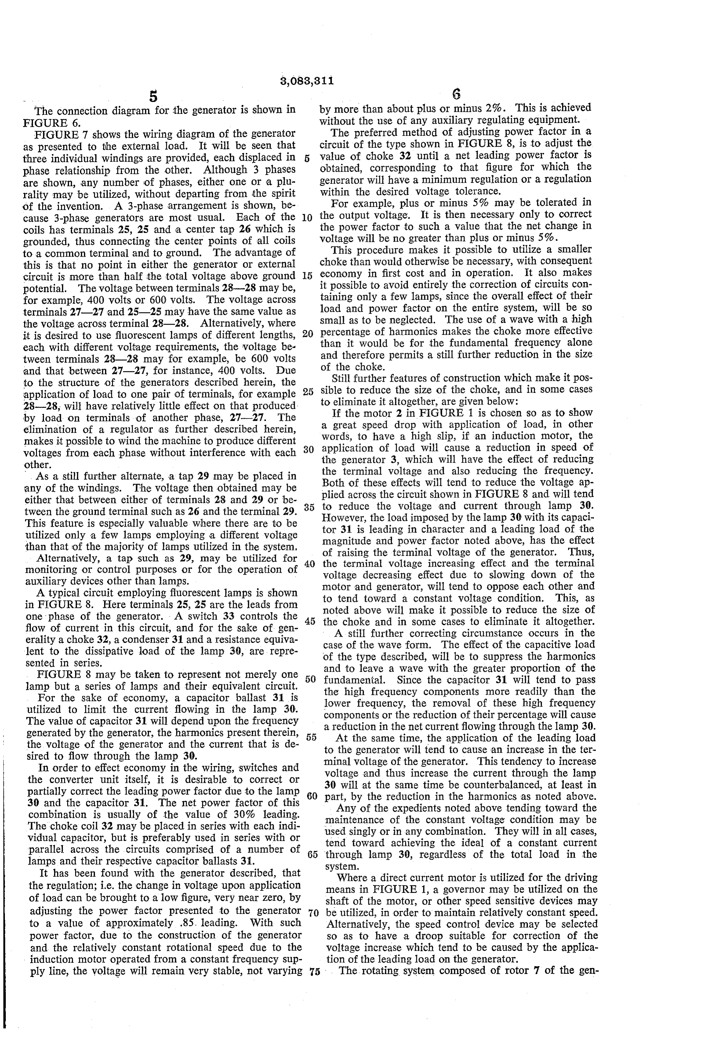
FIGURE 6. the use of any auxiliary regulating equipment. FIGURE 7 shows the wiring diagram of the generator The preferred method of adjusting power factor in a as presented to the external load. It will be seen that circuit of the type shown in FIGURE 8, is to adjust the three individual windings are provided, each displaced in value of choke 32 until a net leading power factor is phase relationship from the other. Although 3 phases obtained, corresponding to that figure for which the are shown, any number of phases, either one or a plu generator will have a minimum regulation or a regulation rality may be utilized, without departing from the Spirit within the desired voltage tolerance. of the invention. A 3-phase arrangement is shown, be For example, plus or minus 5% may be tolerated in cause 3-phase generators are most usual. Each of the O the output voltage. It is then necessary only to correct coils has terminals 25, 25 and a center tap 26 which is the power factor to such a value that the net change in grounded, thus connecting the center points of all coils voltage will be no greater than plus or minus 5%. to a common terminal and to ground. The advantage of choke This procedure makes it possible to utilize a smaller than would otherwise be necessary, with consequent this is that no point in either the generator or external economy circuit is more than half the total voltage above ground 5 in first cost and in operation. It also makes potential. The voltage between terminals 28-28 may be, it possible to avoid entirely the correction of circuits con for example, 400 volts or 600 volts. The voltage across taining only a few lamps, since the overall effect of their terminals 27-27 and 25-25 may have the same value as load and power factor on the entire system, will be so the voltage across terminal 28-28. Alternatively, where small as to be neglected. The use of a wave with a high it is desired to use fluorescent lamps of different lengths, 20 percentage of harmonics makes the choke more effective each with different voltage requirements, the voltage be than it would be for the fundamental frequency alone tween terminals 28-28 may for example, be 600 volts and therefore permits a still further reduction in the size and that between 27-27, for instance, 400 volts. Due of the choke.
to the structure of the generators described herein, the 25 sible Still further features of construction which make it pos application of load to one pair of terminals, for example to reduce the size of the choke, and in some cases 28-28, will have relatively little effect on that produced. to Ifeliminate the it altogether, are given below:
motor 2 in FIGURE 1 is chosen so as to show by load on terminals of another phase, 27-27. The a great speed drop with application of load, in other elimination of a regulator as further described herein, makes it possible to wind the machine to produce different 30 words, to have a high slip, if an induction motor, the application of load will cause a reduction in speed of voltages from each phase without interference with each the generator 3, which will have the effect of reducing other.
As a still further alternate, a tap 29 may be placed in the terminal voltage and also reducing the frequency. any of the windings. The voltage then obtained may be Both of these effects will tend to reduce the voltage ap either that between either of terminals 28 and 29 or be plied across the circuit shown in FIGURE 8 and will tend tween the ground terminal such as 26 and the terminal 29. 35 to reduce the voltage and current through lamp 30. However, the load imposed by the lamp 30 with its capaci
This feature is especially valuable where there are to be tor 31 is leading in character and a leading load of the utilized only a few lamps employing a different voltage magnitude and power factor noted above, has the effect than that of the majority of lamps utilized in the system, of raising the terminal voltage of the generator. Thus, Alternatively, a tap such as 29, may be utilized for the terminal voltage increasing effect and the terminal monitoring or control purposes or for the operation of voltage decreasing effect due to slowing down of the auxiliary devices other than lamps. motor and generator, will tend to oppose each other and A typical circuit employing fluorescent lamps is shown to tend toward a constant voltage condition. This, as in FIGURE 8. Here terminals 25, 25 are the leads from noted above will make it possible to reduce the size of one phase of the generator. - A switch 33 controls the 45 the choke and in some cases to eliminate it altogether. flow of current in this circuit, and for the sake of gen A still further correcting circumstance occurs in the erality a choke 32, a condenser 31 and a resistance equiva case of the wave form. The effect of the capacitive load lent to the dissipative load of the lamp 30, are repre of the type described, will be to suppress the harmonics sented in series.
FIGURE 8 may be taken to represent not merely one 50 and to leave a wave with the greater proportion of the fundamental. Since the capacitor 31 will tend to pass lamp but a series of lamps and their equivalent circuit. the high frequency components more readily than the For the sake of economy, a capacitor ballast 31 is lower frequency, the removal of these high frequency utilized to limit the current flowing in the lamp 30. components or the reduction of their percentage will cause The value of capacitor 31 will depend upon the frequency generated by the generator, the harmonics present therein, 55 a reduction
At the in the net current flowing through the lamp 30.
same time, the application of the leading load the voltage of the generator and the current that is de to the generator will tend to cause an increase in the ter sired to flow through the lamp 30. minal voltage of the generator. This tendency to increase In order to effect economy in the wiring, switches and voltage and thus increase the current through the lamp the converter unit itself, it is desirable to correct or 30 will at the same time be counterbalanced, at least in partially correct the leading power factor due to the lamp 60 part, by the reduction in the harmonics as noted above. 30 and the capacitor 31. The net power factor of this Any of the expedients noted above tending toward the combination is usually of the value of 30% leading. maintenance of the constant voltage condition may be The choke coil 32 may be placed in series with each indi used singly or in any combination. They will in all cases, vidual capacitor, but is preferably used in series with or tend toward achieving the ideal of a constant current parallel across the circuits comprised of a number of 65 through lamp 30, regardless of the total load in the lamps and their respective capacitor ballasts 3. system.
It has been found with the generator described, that Where a direct current motor is utilized for the driving the regulation; i.e. the change in voltage upon application means in FIGURE 1, a governor may be utilized on the of load can be brought to a low figure, very near Zero, by adjusting the power factor presented to the generator 70 shaft of the motor, or other speed sensitive devices may be utilized, in order to maintain relatively constant speed.
to a value of approximately .85. leading. With such Alternatively, the speed control device may be selected power factor, due to the construction of the generator so as to have a droop suitable for correction of the and the relatively constant rotational speed due to the voltage increase which tend to be caused by the applica induction motor operated from a constant frequency Sup tion of the leading load on the generator. ply line, the voltage will remain very stable, not varying 75 The rotating system composed of rotor 7 of the gen
Page 6
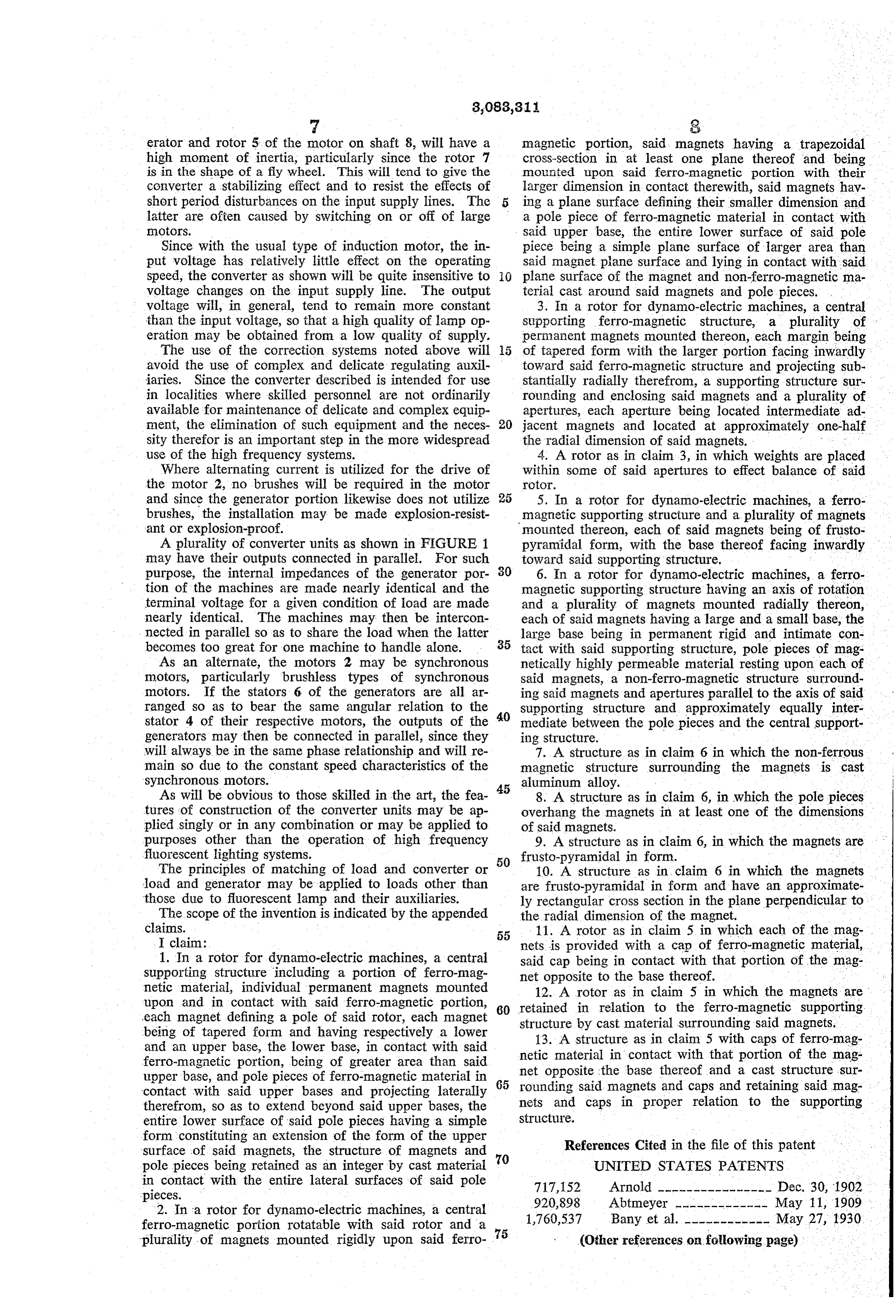
erator and rotor 5 of the motor on shaft 8, will have a magnetic portion, said magnets having a trapezoidal high moment of inertia, particularly since the rotor 7 cross-section in at least one plane thereof and being is in the shape of a fly wheel. This will tend to give the mounted upon said ferro-magnetic portion with their converter a stabilizing effect and to resist the effects of larger dimension in contact therewith, said magnets hav short period disturbances on the input supply lines. The ing a plane surface defining their smaller dimension and latter are often caused by switching on or off of large a pole piece of ferro-magnetic material in contact with notors. said upper base, the entire lower surface of said pole Since with the usual type of induction motor, the in piece being a simple plane surface of larger area than put voltage has relatively little effect on the operating said magnet plane surface and lying in contact with said speed, the converter as shown will be quite insensitive to plane surface of the magnet and non-ferro-magnetic ma voltage changes on the input supply line. The output terial cast around said magnets and pole pieces. voltage will, in general, tend to remain more constant 3. In a rotor for dynamo-electric machines, a central than the input voltage, so that a high quality of lamp op supporting ferro-magnetic structure, a plurality of eration may be obtained from a low quality of Supply. permanent magnets mounted thereon, each margin being The use of the correction systems noted above will of tapered form with the larger portion facing inwardly avoid the use of complex and delicate regulating auxil toward said ferro-magnetic structure and projecting sub iaries. Since the converter described is intended for use stantially radially therefrom, a supporting structure sur in localities where skilled personnel are not ordinarily rounding and enclosing said magnets and a plurality of available for maintenance of delicate and complex equip apertures, each aperture being located intermediate ad ment, the elimination of such equipment and the neces 20 jacent magnets and located at approximately one-half sity therefor is an important step in the more widespread the radial dimension of said magnets. use of the high frequency systems. 4. A rotor as in claim 3, in which weights are placed Where alternating current is utilized for the drive of within some of said apertures to effect balance of said the motor 2, no brushes will be required in the motor rotor.
and since the generator portion likewise does not utilize 25 5. In a rotor for dynamo-electric machines, a ferro brushes, the installation may be made explosion-resist magnetic supporting structure and a plurality of magnets ant or explosion-proof. mounted thereon, each of said magnets being of frusto A plurality of converter units as shown in FIGURE 1 pyramidal form, with the base thereof facing inwardly may have their outputs connected in parallel. For such toward said supporting structure.
purpose, the internal impedances of the generator por 30 6. In a rotor for dynamo-electric machines, a ferro tion of the machines are made nearly identical and the magnetic supporting structure having an axis of rotation terminal voltage for a given condition of load are made and a plurality of magnets mounted radially thereon, nearly identical. The machines may then be intercon each of said magnets having a large and a small base, the nected in parallel so as to share the load when the latter large base being in permanent rigid and intimate con becomes too great for one machine to handle alone. 35 tact with said supporting structure, pole pieces of mag As an alternate, the motors 2 may be synchronous netically highly permeable material resting upon each of motors, particularly brushless types of synchronous said magnets, a non-ferro-magnetic structure surround motors. If the stators 6 of the generators are all ar ing said magnets and apertures parallel to the axis of said ranged so as to bear the same angular relation to the 40 supporting structure and approximately equally inter stator 4 of their respective motors, the outputs of the mediate between the pole pieces and the central support generators may then be connected in parallel, since they ing structure. - will always be in the same phase relationship and will re 7. A structure as in claim 6 in which the non-ferrous main so due to the constant speed characteristics of the magnetic structure surrounding the magnets is cast synchronous motors. 45 aluminum alloy.
As will be obvious to those skilled in the art, the fea 8. A structure as in claim 6, in which the pole pieces tures of construction of the converter units may be ap overhang the magnets in at least one of the dimensions plied singly or in any combination or may be applied to of said magnets. - purposes other than the operation of high frequency 9. A structure as in claim 6, in which the magnets are fluorescent lighting systems. frusto-pyramidal in form.
The principles of matching of load and converter or 50 10. A structure as in claim 6 in which the magnets load and generator may be applied to loads other than are frusto-pyramidal in form and have an approximate those due to fluorescent lamp and their auxiliaries. ly rectangular cross section in the plane perpendicular to The scope of the invention is indicated by the appended the radial dimension of the magnet.
55 11. A rotor as in claim 5 in which each of the mag
I claim: nets is provided with a cap of ferro-magnetic material, 1. In a rotor for dynamo-electric machines, a central said cap being in contact with that portion of the mag supporting structure including a portion of ferro-mag net opposite to the base thereof. netic material, individual permanent magnets mounted 12. A rotor as in claim 5 in which the magnets are upon and in contact with said ferro-magnetic portion, retained in relation to the ferro-magnetic supporting each magnet defining a pole of said rotor, each magnet 60 structure by cast material surrounding said magnets. being of tapered form and having respectively a lower 13. A structure as in claim 5 with caps of ferro-mag and an upper base, the lower base, in contact with said netic material in contact with that portion of the mag ferro-magnetic portion, being of greater area than said upper base, and pole pieces of ferro-magnetic material in 65 net opposite the base thereof and a cast structure sur rounding said magnets and caps and retaining Said mag contact with said upper bases and projecting laterally therefrom, so as to extend beyond said upper bases, the nets and caps in proper relation to the supporting entire lower surface of said pole pieces having a simple Structure.
form constituting an extension of the form of the upper References Cited in the file of this patent surface of said magnets, the structure of magnets and pole pieces being retained as an integer by cast material 70 UNITED STATES PATENTS in contact with the entire lateral surfaces of said pole 717, 152 Arnold ---------------- Dec. 30, 1902 pieces. 920,898 Abtmeyer ------------- May 11, 1909 2. In a rotor for dynamo-electric machines, a central ferro-magnetic portion rotatable with said rotor and a 75 1,760,537 Bany et al. ------------ May 27, 1930 plurality of magnets mounted rigidly upon said ferro (Other references on following page)
Page 7
UNITED STATES PATENTS 2,516,901 Morrill ---------------- Aug. 1, 1950 1,799,156 Dorning --------------- Apr. 7, 1931 2,673,302 Gynt ----------------- Mar. 23, 1954 1,807,218 Langewiesche --------- May 26, 1931 2,695,375 Mendenhall et al. -------- Nov. 23, 1954 2,138,231 Gebhardt -------------- Nov. 29, 1938 2,697,176 Keith ----------------- Dec. 14, 1954 2,232,773 Daiger ---------------- Feb. 25, 1941 2,697,192 Wiley ----------------- Dec. 14, 1954 2,245,924 Kennedy -------------- June 17, 1941. 2,703,862 Gordon --------------- Mar. 8, 1955 2,383,143 Moore ---------------- Aug. 21, 1945 FOREIGN PATENTS 2,488,729 Kooyman -------------- Nov. 22, 1949 668,436 Germany --------------- Dec. 3, 1938
Provenance
- Collection
- Cited prior art
- Original PDF
- patentimages.storage.googleapis.com →
- Filed
- 1956-11-08
- Pages
- 7
- Method
- pdftotext (the PDF's own text layer) + pdftoppm 300dpi page scans
- Source
- Google Patents bibliographic record
- Granted
- 1963-03-26
- Inventors
- Krasnow Shelley
- Transcribed from
- patentimages.storage.googleapis.com →