patent · US3392910
Seal
16 July 1968
Page 1
Drawing sheet — no readable text.
Page 2
Drawing sheet — no readable text.
Page 3
Drawing sheet — no readable text.
Page 4
United States Patent Office Patented July3,392,910
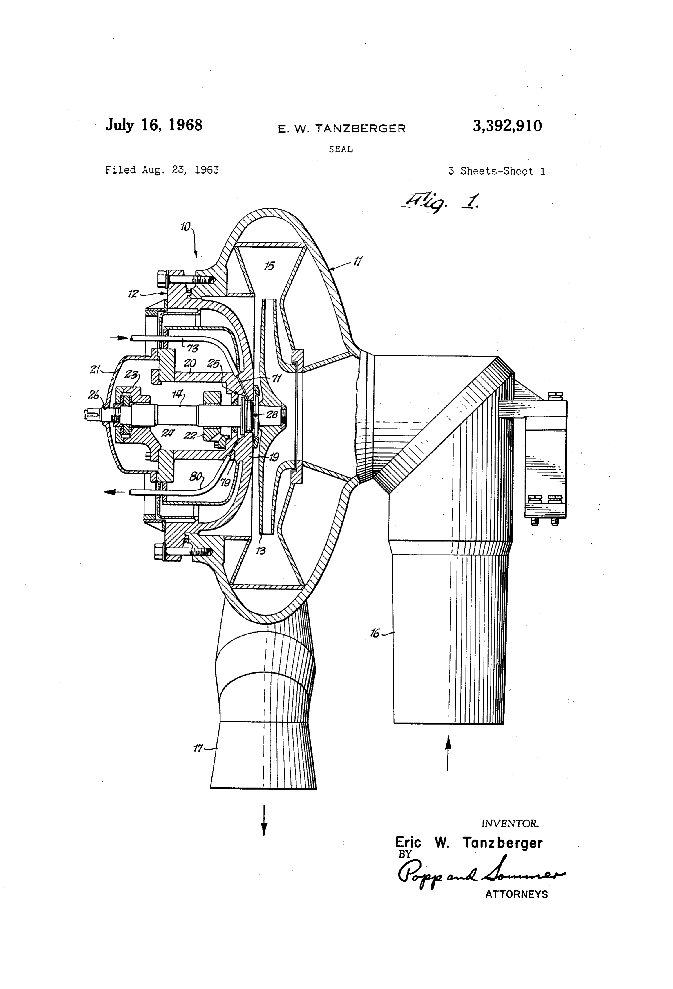
head assemblies 11 and 12 so as to draw gas through an 3,392,910 inlet duct 16 and discharge it after being compressed
SEAL through an outlet duct 17.
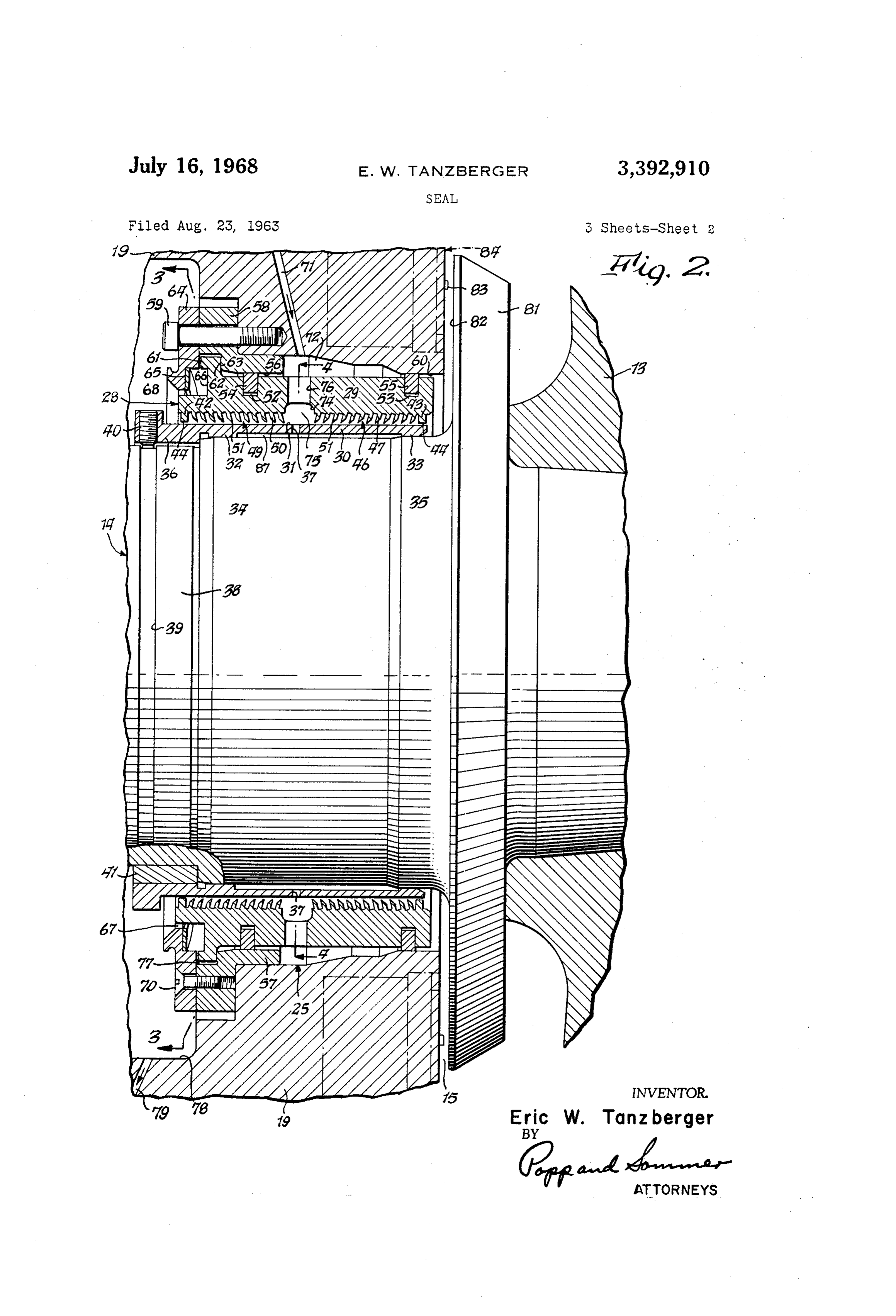
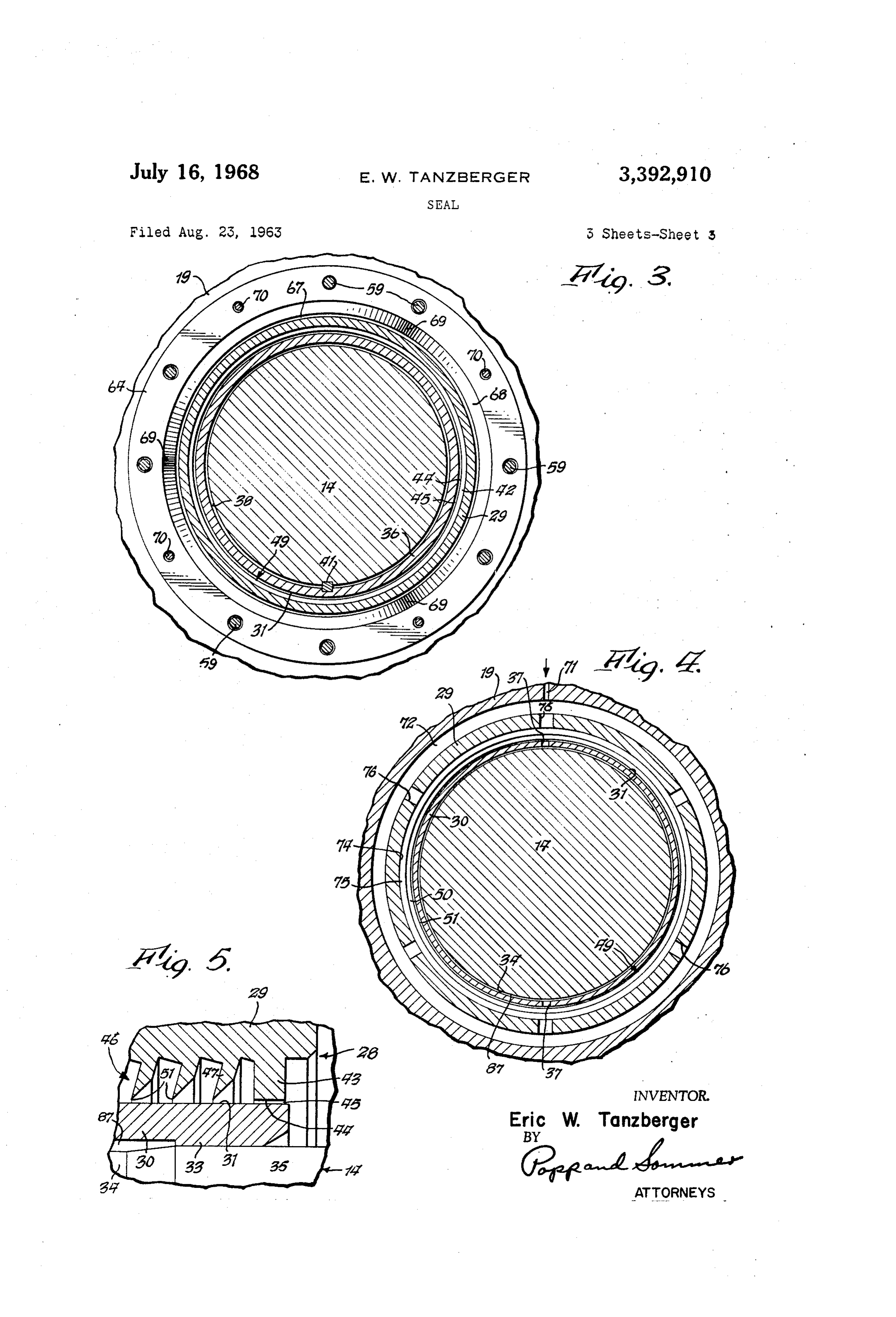
Eric W. Tanzberger, Allegany, N.Y., assignor, by mesne The end head assembly 12 is shown as including a seal assignments, to the United States of America as repre housing portion. 19, a barrel portion 20 extending lateral sented by the United States Atomic Energy Commission ly outwardly therefrom, and a cover 21 closing the outer Filed Aug. 23, 1963, Ser. No. 304,031 end of this barrel portion. The impeller shaft 14 is shown 15 Claims. (C. 230-132) as journalled on an inner bearing assembly 22 and an out This invention relates to an improved seal between er thrust and journal bearing assembly 23. These bearing relatively rotating parts, and more particularly to a seal 0 assemblies are arranged within a compartment 24 jointly effective against the escape of fluid through an opening provided by the parts 19-21 of the end head assembly 12 in apparatus including a casing providing a chamber in and are suitably mounted thereon. The impeller drive which relatively high pressure fluid may be confined and shaft extends through openings in the members which having such opening through which a rotary member provide the end walls for the compartment 24. The in extends. 15 ner opening, generally designated 25, is provided in the The primary object of the present invention is to pro seal housing portion. 19. The outer opening is shown at vide such a seal which has a high degree of effectiveness 26The and provided in the cover 21. seal assembly of the present invention and repre in preventing the escape of fluid to be confined. sented generally by the numeral 28 is arranged operatively Another object is to provide such a seal which main in the opening 25 between the seal housing portion 19 and tains its high degree of effectiveness over a wide varia 20 shaft 14 and is effective against the escape of gas from tion in environmental temperature which promotes dimen sional change of structural parts. the impeller chamber 15 through this opening 25. Another object is to provide such a seal which nor The seal assembly 28 is shown as including a stationary mally has no structural part contacting the rotary mem 25 labyrinth seal ring 29 which surrounds a rotatable sleeve ber and therefore is not subjected to wear. 30 suitably mounted on the rotary shaft 14 so as to ro A further object is to provide such a seal which is so tate therewith and having a cylindrical peripheral sur face 31 concentric with the shaft axis. While this shaft constructed that even if contact between it and the rotary member occurs it will not be damaged to lose its sealing sleeve 30 may be mounted in any suitable manner, it is effectiveness. shown as having a pair of axially spaced internal annular A further object is to provide such a seal which is rela 30 ribs 32 and 33 provided with internal cylindrical surfaces tively simple in construction. engaging external cylindrical surfaces 34 and 35, respec While the inventive seal may be used in any suitable tively, provided on the shaft 14. Between these ribs 32 and apparatus, it has particular advantageous application in of 33 the shaft sleeve 30 is shown as provided with a pair a centrifugal gas compressor handling a process gas of 35 diametrically opposed radial holes 37 for a purpose such nature that it is most important to prevent its escape hereinafter explained. The outer end portion 36 of the from the compressor casing along the impeller drive shaft sleeve 30 is radially thicker and surrounds a cylin drical shaft portion 38 of reduced diameter provided shaft.
An example is a centrifugal compressor used as a heli with an annular external groove 39. This sleeve portion um recirculator in a nuclear plant where the helium gas 40 36 is shown as carrying a radially disposed set screw 40 becomes radioactively contaminated and the sealing prob the inner end of which enters the shaft groove 39 so as lem is rendered particularly difficult because of the low to prevent relative axial movement between the sleeve molecular weight of the helium which inherently pro 30 and the shaft 14. A key 41 is shown as operatively in vides it with high penetrability. terposed between the sleeve portion 36 and the shaft por Other objects and advantages of the present invention 45 tion 38 to prevent relative rotation between the sleeve 30 will be apparent from the following detailed description and the shaft 14. Since the sleeve 30 is thus fixed against both axial and rotative movement relative to the shaft 14 of a preferred embodiment thereof illustrated as applied it can be considered a part thereof. to a centrifugal gas compressor in the accompanying drawings wherein: The seal ring 29 is shown as integrally formed on its FIG. 1 is a side view of a centrifugal gas compressor, 50 inside with axially spaced outer and inner annular abut ment members 42 and 43, the latter being adjacent the partly in elevation and partly in section, equipped with a impeller seal assembly constructed in accordance with the princi has a radially 13. Each of these abutment members 42 and 43 ples of the present invention. inwardly facing cylindrical land surface FIG. 2 is an enlarged fragmentary longitudinal central 44 which opposes the radially outwardly facing cylin sectional view of the seal assembly shown in FIG. 1 and 55 drical spaced surface 31 on the shaft sleeve 30 and is normally therefrom to provide a clearance indicated typical associated compressor parts. ly at 45 in FIG. 5 for the inner abutment member 43. FIG. 3 is a fragmentary transverse sectional view there The land surfaces 44 of the two abutment members 42 of taken on line 3-3 of FIG. 2. and 43 are concentric and shown as having the same in FIG. 4 is a fragmentary transverse sectional view there side diameter. While the clearance 45 is normally pro of taken on line 4-4 of FIG. 2. 60 vided between each abutment land surface 44 and the FIG. 5 is a still further enlarged fragmentary longitu dinal central sectional view of an end portion of the seal opposing after shaft sleeve surface 31, for a purpose herein explained, these surfaces 44 and 31 are adapted assembly in FIG. 1 and associated compressor parts. to engage each other.
The centrifugal gas compressor is shown as having a stationary casing represented generally at 10 which in 65 its The seal ring 29 is also shown as integrally formed on inside with axially spaced inner and outer groups of cludes a housing assembly 11 having an opening on one annular side which is closed by a removable end head assembly abutmentlabyrinth seal elements arranged between the members 42 and 43. The inner group designated 12. Through this opening is inserable an impeller 13 suita bly fastened to one end of a horizontal drive shaft 14. 46 comprises a plurality of annular labyrinth seal ele ments severally represented at 47, and the outer group
The impeller 13 may be of any suitable construction and 70 designated 49 comprises a plurality of annular labyrinth is arranged for rotation within a chamber 15 of Suitable seal elements severally represented at 50. The seal ele configuration jointly provided by the housing and end
Page 5
ments 47 are shown as being similar one to another and ring 29 against radial movement relative to the casing in the nature of circular ribs or fins inclined from base portion i9. For this purpose, the ring 29 is shown as to tip in a direction extending radially inwardly and axial formed to provide a radially outwardly extending integral ly outwardly away from the impeller chamber 15. On annular rib 61 having an annular radial surface 62 which the other hand, while the seal elements 50 are also shown 5 faces axially toward the impeller chamber 15. This sur as circular ribs or fins similar one to another, they are face 62 opposes and contacts an axially facing radial Sur inclined from base to tip in a direction extending radially face 63 formed on the member 58. A retainer ring 64 is inwardly and axially inwardly toward the impeller cham shown as arranged axially outwardly of the rib 61 and ber 15. Thus the seal elements in one of the groups 46 overlaps the same in space relation thereto and is formed or 49 thereof are inclined convergently in a radially in 0. to provide an axially and inwardly facing radial surface ward direction with respect to the seal elements in the 65 which opposes and is spaced substantially from an other of these groups. Each of the labyrinth seal ele axially outwardly facing radial surface 66 formed on the ments 47 and 59 is shown as having parallel side Sur seal ring 29. In the space provided between the separated faces with one adjacent its tip margin being tapered to surfaces 65 and 66 are arranged spring means which force ward the other to provide a continuous annular ridge the surfaces 62 and 63 in contact with each other. or tip 51 which has a circular configuration when viewed While such spring means may be constructed in any axially and is concentric with the abutment land surfaces suitable manner, the same is illustrated as an annular 44 and has a comparatively much shorter width in an leaf spring 68, wider in a radial than an axial direction, axial direction. The circular tips 51 of all seal elements and bent back and forth in an axial direction in a uni 47 and 50 are concentric with each other and have the 20 form undulating manner so as to provide a plurality of same diameter. alternate salient portions 69 on opposite axial sides of An important feature of the present invention is that the spring, three such undulations or waves being shown the cylindrical land surface 44 of each of the abutment as provided on each axial side. The salients 69 and on members 42 and 43 has a much greater width in an axial one axial side of such wave spring bear against the Sur direction than any of the tips 51 of the labyrinth seal ele face 65 and on the other axial side engage the surface ments 47 and 50. 66. The wave spring 68 is flexed axially when in opera Another important and related feature of the present tive position between the surfaces 65 and 66 and thus pre invention is that the inside diameter of the land surfaces loaded so as to urge the clamp surfaces 62 and 63 into 44 is no greater than that of the tips 51. in other words, frictional contact with each other. the land surfaces 44 are arranged radially inwardly at An annular clearance 67 is shown as provided at all least as far as the tips 51. Thus should there be radial times between the radially outwardly facing surface of displacement of the ring 29 relative to the shaft sleeve the outer end portion of the seal ring 29 and the sur 30 so as to bring there two members into contact with rounding inwardly facing surfaces of the spring 68 and each other, the land surfaces 44 wiil engage the periph retainer ring 64. A similar annular clearance 77 is pro eral surface 31 on the shaft sleeve 30 at least as soon vided between the opposing radially facing surfaces of as the tips 51 engage such surface 31. If the inside di the seal ring rib 61 and seal housing member 58. These ameter of the land surface 44 is slightly less than that clearances 77 and 67 permit relative radial movement for the tips 51, as may be desired in some applications, between the seal ring 29 and casing portion 19. it will be seen that the land surface 44 will engage the The retainer ring 64 is shown as fastened to the seal shaft sleeve surface 31 and prevent contact of the tips 40 housing member 58 by a plurality of flat headed machine 51 with such surface. Radial contact of the ring 29 with screws 70 arranged at circumferentially spaced intervals. the shaft sleeve 30, whether in advance or substantially The screws 70 pass through openings in the retainer ring simultaneously with the seal element tips 51, will prevent 64 and have their threaded shank ends received in inter damage to these tips. Thus the abutment land Surfaces nally threaded holes provided in the seal housing member act as bumpers to prevent damage to the tips of the laby 58. As shown in FIG. 3 such machine screws 70 are ar rinth seal elements. ranged on opposite sides of every pair of adjacent cap Seal means are shown as being operatively interposed screws 59, four machine screws 70 and eight cap screws between the seal ring 29 and the surrounding casing por 59 being shown.
tion 19 and such means allows relative radial movement A feature of the present invention is that the wave therebetween. For this purpose, the ring 29 is shown as provided with a pair of axially spaced outer and inner 50 spring surfaces 68 effects a frictional contact between the clamp 62 and 63 which is sufficient to hold the seal ring grooves 52 and 53, respectively. Arranged in the groove 29 in an elevated position off the shaft sleeve 30 in order 52 is an annular split ring 54. A similar split ring 55 is normally to provide the annular clearances 45. In other arranged in the other groove 53. The split rings 54 and words, the ring 29 is yieldably held to overcome its gravity 55 are of the piston ring type, variable in circumferential effect.
extent and biased radially outwardly into sealing engage Means are provided for flowing fluid between the tips 51 ment with an opposing Surface. In the case of the ring of the inner group 46 of labyrinth seal elements 47 and the 54, its peripheral surface engages an internal cylindrical shaft sleeve surface 3 in a direction toward the inner surface 56 formed on the annular flange portion 57 of end of such group and into the chamber 15, and also for an annular seal housing member 58. The flange portion flowing fluid between the tips 5i of the outer group 49 of 57 extends axially inwardly from the radially inner end 60 labyrinth seal elements 50 in a direction toward the outer of the member 58 which is secured to the casing portion end thereof, whereby the ring 29 is fluid filled along the 19 by a series of circumferentially spaced cap screws 59 shaft. For this purpose, the casing portion 19 is shown passing through holes provided in the member 58 and as provided with an inlet passage 71 the inner end of having their threaded shank ends received in internally which communicates with the annular space 72 provided threaded recesses provided in the casing portion 19. In between the axially spaced outer and inner split rings 54 the case of the other split ring 55, its peripheral surface and 55, respectively. The outer end of this inlet passage 71 opposes and engages an internal cylindrical surface 60 is suitably connected to a supply conduit 73 which leads formed on the casing portion 9, Such surface 60 con to any suitable source (not shown) of pressurized fluid stituting a wall portion of the opening 25. The surfaces 56 and 60 have a radial clearance with the opposing pe 70 suitable to be used for sealing purposes. Further, the ring 29 is shown as provided with an inter ripheral surface of the seal ring 29. Of course, the mem nal annular groove 74 between the axially spaced labyrinth ber 58 may be eliminated as a separate part so that the Seal groups 46 and 49 to provide the annular space 75 surface 56 may also be formed directly on the casing part therebetween. As best shown in FIG. 4, the ring 29 is 19 if desired.
Means are also shown for yieldingly holding the seal also shown as provided with a series of radial through passages 76 arranged at circumferentially spaced inter
Page 6
vals, six such passages being shown. These passages 76 expansion of 13 x 106 inch per degree F., and that the establish communication between the radially outer an shaft 14 and its sleeve 30 are constructed of an alloy nular space 72 and the radially inner annular space 75. composed principally of iron such as AISI type 410 stain This space 75 also communicates with the outer ends of less steel specified by American Iron and Steel Institute the shaft sleeve holes 37 the inner ends of which com and having a coefficient of expansion of 7x106 inch per municate with an annular space 87 provided by the radial degree F.
clearance between the shaft surface 34 and internal Sur It is further assumed that the radial clearances 45 be face of the sleeve 30 between the internal ribs 32 and 33 tween the opposing abutment land surfaces 44 and shaft thereof. sleeve surface 31 is from about 0.003 inch to about 0.005 Fluid which flows inwardly or to the right as viewed in O inch, and further that the radially inward overlap, if any, FIG. 2 passes the tips of the labyrinth seal elements 47 of the abutment land surfaces 44 with respect to the and flows through the clearance 45 at the inner abutment labyrinth seal elements tips 51 does not exceed about member 43 to enter the impeller chamber 15. Fluid which 0.002 inch. These dimensions are given purely for illus flows outwardly or to the left passes the tips of the trative purposes, considering the nature of the rotary ap labyrinth seal elements 50 and flows through the clearance 15 paratus and the specific type of process gas being handled 45 at the outer abutment member 42 to enter a drain together with its temperature and pressure. compartment 78 which has an outlet passage 79 formed in Let it further be assumed that helium seal gas is fed the casing portion 19. The outer end of this drain passage from any suitable source through the inlet conduit 73 79 is shown as being suitably connected in fluid conduct such that the presssure of this seal gas in the inner an ing communication with a drain conduit 80 which leads to 20 nular space 75 is about 353 p.s. i., and that a back pres any suitable receptacle (not shown) in which a desired sure in the drain compartment 78 is suitably maintained back pressure may be maintained for a purpose hereinafter at a pressure of about 352 p.s. i. It will thus be seen that explained. Likewise, any axially outward leakage of fluid there exists a pressure differential across the inner from the space 87 past sleeve rib 32 enters drain compart labyrinth seal group 46 of about 3 p.s.i. to cause flow ment 78 and any axially inward leakage of fluid from this 25 of seal gas toward the impeller chamber 15, and that a space past sleeve rib 33 escapes into impeller chamber 15. pressure differential of about 1 p.s. i. is developed across Another important feature of the present invention is the outer labyrinth seal group 49 to cause a flow of seal that the labyrinth seal ring 29 is constructed of a metallic gas axially outwardly away from the impeller chamber material having a higher thermal coefficient of expansion 15. It will also be noted that the pressure at any point than that of the metallic material of which the shaft sleeve 30 along the axial extent of the labyrinth seal assembly is 30 and shaft 14 are constructed. This tends to maintain at a higher pressure than that which obtains within the substantially the normal intended radial clearances 45 impeller chamber 15. Typically, the flow of helium seal between the parts 29 and 30 even though there is a wide gas axially inwardly over the inner labyrinth seal group difference in the temperatures of these parts. If the parts 46 is 120 standard cubic feet per minute (hereinafter were made of the same material or of materials having referred to as c.f.m.) and the flow of helium seal gas substantially the same coefficient of expansion, the shaft axially outwardly over the outer labyrinth seal group 49 sleeve 30 which gets hotter than the seal ring 29, as more is about 60 standard c.f.m. The labyrinth seal ring is fully explained later herein, would cause these parts to thus gas filled along the shaft and hence gas lubricated. seize each other causing destruction of the seal assembly Inasmuch as the annular space 87 between the shaft 28 if the shaft were continued to be rotated. 40 14 and its sleeve 30 is also filled with seal gas at a high Referring to FIG. 2, the impeller shaft 14 is shown as er pressure than the pressure of gas in either the impel having a radially outwardly extending annular continuous ler chamber 5 or the drain compartment 78, if the con flange 81 provided with an axially and outwardly facing tacts between the sleeve ribs 32 and 33 and correspond radial side face 82 adapted to be engaged by the annular ing shaft surfaces 34 and 35 are not gas tight, seal gas movable element 83 of a bellows seal assembly indicated will leak axially from the space 87 into this chamber generally at 84, these parts 83 and 84 being phantomly and compartment. Thus again as is desired, process gas illustrated. The purpose of this assembly 84 is to cause is prevented from leaking axially outwardly from the contact of the element 83 with the side face 82 to effect impeller chamber 15.
a sealed engagement when the compressor is shut down. It will also be noted that the annular space 72 be However, since this shut down seal assembly 84 forms no 50 tween the seal ring 29 and the surrounding casing is filled part of the present invention, further explanation of the with seal gas at a higher pressure than the pressure of details of its construction and operation are not given. gas in either chamber 15 or compartment 78. Since the While other seal means may be provided between the piston type seal rings 54 and 55 will allow some leak compressor shaft and casing and arranged axially out age as a practical matter, it will be in the proper direc wardly of the inventive seal assembly 28, such additional 55 tion, namely, past ring 55 toward chamber 15 to block seal means have not been illustrated since they form no escape of process gas therefrom and past ring 54 to be part of the present invention. collected in drain compartment 78. In this latter con Operation nection, the leaking seal gas flows between the contact
The operation of the inventive seal assembly 28 in the ing surfaces 62 and 63 which also as a practical matter illustrated application of the same to a centrifugal gas 60 The would be ineffective to prevent gas flow therebetween. compressor is believed to be best explained by assuming downstream communicating clearances between the various parts typical figures as to temperature and pressures and with of the surfaces 62 and 63 would conduct the process gas handled by the compressor being con the leaking gas ultimately to drain compartment 78. sidered specifically as helium. Thus, let it be assumed that The helium seal gas is supplied at say room tempera ture and hence is relatively cool as compared to the the impeller shaft 14 is being driven by a prime mover 65 process (not shown) and that the compressor is connected in a gas in the impeller chamber which may be as system in which the helium process gas is being circulated, Sumed to be at a temperature of somewhere between 600 such that the pressure of the gas in the impeller chamber and 700 F. Thus the seal gas flowing through the an 15 is about 350 pounds per square inch (hereinafter re nular spaces 72, 75 and 87 connected by the radial pas ferred to as p.s. i.). 70 sages 76 and 37 will tend to cool the ring 29. On the Let it further be assumed that the labyrinth seal ring other hand, the shaft portion including the sleeve 30 29 with its integral abutment members and labyrinth seal surrounded by the seal ring 29 will absorb heat from the elements is constructed of an alloy composed principally process gas and therefore may be at a temperature in the of aluminum such as Alcoa type A 750 specified by Alu range of from 600 to 700 F. in the assumed example. minum Company of America and having a coefficient of 75 A substantial temperature difference therefore exists be
Page 7
tween the parts 29 and 30. Since the shaft with its sleeve inwardly toward said rotary member, abutment elements 30 is constructed of a material having a lower coefficient on the inside of said ring at opposite axial ends of Said of expansion than that of the material of which the ring seal elements and extending radially inwardly at least as 29 is composed, the original intended radial clearances far as said seal elements to provide land surfaces oppos 45 between the opposing surfaces of the abutment mem ing said rotary member and normally spaced therefrom bers 42, 43 and the sleeve 30 will be substantially main but adapted to engage the same, and seal means operative tained even though the temperature of the seal ring 29 ly interposed between said ring and casing. is substantially below that of the shaft sleeve 30. In 2. In apparatus including a casing providing a chamber other words, while the ring 29 is cooler it has a higher. in which a relatively high pressure fluid may be confined coefficient of expansion, as compared with the shaft O and having an opening through which a rotary member sleeve 30 which has a higher temperature and a lower extends, the combination there with of means to seal coefficient of expansion. against the escape of fluid through said opening compris The opposing axially facing surfaces 62 and 63 pro ing a ring arranged within said opening and Surrounding vided between the seal ring 29 and surrounding Seal said rotary member, annular labyrinth seal elements on housing member 58, the latter in effect being part of the 15 the inside of said ring and extending radially inwardly to compressor casing, serve as clamp or clutch Surfaces ward said rotary member, abutment elements on the in having frictional contact maintained by the pressure of side of said ring at opposite axial ends of said Seal ele the wave spring 68. Since these surfaces 62 and 63 are ments and extending radially inwardly at least as far as radial there can be relative radial movement between said seal elements to provide land surfaces opposing said the ring 29 and the surrounding casing, the clearances 20 rotary member and normally spaced therefrom but 67 and 77 permitting of this. It is intended that the wave adapted to engage the same, seal means operatively inter spring 68 will have a spring rate such that it will exert posed between said ring and casing and allowing rela sufficient force between the surfaces 62 and 63 to develop tive radial movement therebetween, and means yieldably a frictional contact at least adequate to support the holding said ring against radial movement relative to Said weight of the ring 29 and the associated parts mounted 25 casing.
thereon such as the split seal rings 54 and 55. Thus the 3. In apparatus including a casing providing a chamber ring 29 may be radially supported on the casing so as in which a relatively high pressure fluid may be confined to have clearances 45 between it and the shaft sleeve and having an opening through which a rotary member 30 around the full circumference of this sleeve. In the extends, the combination there with of means to seal event temperature changes produce dimensional growth 30 against the escape of fluid through said opening compris radially or even distortion of the shaft and its sleeve 20 ing a ring arranged within said opening and surrounding so as to effect intermittent or continuous contact with said rotary member, annular labyrinth seal elements on the seal ring 29, it will be seen that the brunt of such the inside of said ring and extending radially inwardly to contact will be taken by the abutment land surfaces 44 ward said rotary member, abutment elements on the in engaging the shaft sleeve surface 31. Should such con 35 side of said ring at opposite axial ends of said seal ele tact between the seal ring 29 and the shaft sleeve 30 be ments and extending radially inwardly at least as far as sufficiently forceful to displace the seal ring in a radial said seal elements to provide land surfaces opposing said direction, this can take place because the clamp surfaces rotary member and normally spaced therefrom but 62 and 63 will slide one on the other to permit of this. adapted to engage the same, and seal means operatively Also, it will be seen that such radial shift in the posi 40 interposed between said ring and casing and including tion of the seal ring 29 relative to the surrounding com split ring means variable in circumferential extent. pressor casing will be accommodated by the split seal 4. In apparatus including a casing providing a chamber rings 54 and 55 sliding in their respective grooves 52 and in which a relatively high pressure fluid may be confined 53 while maintaining effective sealing engagement with and having an opening through which a rotary member the surrounding casing parts. extends, the combination therewith of means to seal While the inventive seal assembly 28 has been de against the escape of fluid through said opening compris scribed in its illustrated application as sealing against ing a ring arranged within said opening and surrounding the lakage of a gaseous process fluid and employing a said rotary member, annular labyrinth Seal elements on gaseous seal fluid of the same type, it will be under the inside of said ring and extending radially inwardly to stood that the process and seal fluids may be specifical 50 ward said rotary member, abutment elements on the in ly different gases if this is considered desirable for any side of said ring at opposite axial ends of said seal ele reason. Generally speaking, the higher the molecular ments and extending radially inwardly at least as far as weight of the seal and process gases, everything else be said seal elements to provide land surfaces opposing said ing equal, the greater may be the normal radial clear rotary member and normally spaced therefrom but ances 45, and vice versa. Of course, if considered suit 55 adapted to engage the same, and seal means operatively able in a given application of the seal assembly 28, either interposed between said ring and casing and including or both of the process and seal fluids may be liquid. means providing an annular groove in one of said rings From the foregoing, it will be seen that the seal as and casing and a split ring variable in circumferential ex sembly of the present invention accomplishes the vari tent arranged in said groove and biased radially into seal ous objects stated. Since modifications and changes in 60 ing engagement with the other of said ring and casing. the construction of the seal assembly and the apparatus 5. In apparatus including a casing providing a chamber with which it is associated may occur to those skilled in which a relatively high pressure fluid may be confined in the art, the embodiment shown and described is in and having an opening through which a rotary member tended to be illustrative and not limitative of the present extends, the combination therewith of means to seal invention the scope of which is to be measured by the 65 against the escape of fluid through said opening com appended claims. prising a ring arranged within said opening and surround What is claimed is: ing said rotary member, annular labyrinth seal elements 1. In apparatus including a casing providing a cham on the inside of said ring and extending radially inwardly ber in which a relatively high pressure fluid may be con toward said rotary member, abutment elements on the fined and having an opening through which a rotary 70 inside of said ring at opposite axial ends of said seal ele member extends, the combination therewith of means to ments and extending radially inwardly at least as far as seal against the escape of fluid through said opening said Seal elements to provide land surfaces opposing said comprising a ring arranged within said opening and sur rotary member and normally spaced therefrom but rounding said rotary member, annular labyrinth seal ele adapted to engage the same, and seal means operatively ments on the inside of said ring and extending radially 75 interposed between said ring and casing and including first
Page 8
and second split ring means severally variable in circum posing said rotary member and normally spaced there ferential extent and spaced from each other axially of said from but adapted to engage the same, and Seal means ring. operatively interposed between said ring and casing, said 6. In apparatus including a casing providing a chamber ring being constructed of an alloy composed principally in which a relatively high pressure fluid may be confined of aluminum and said rotary member being constructed and having an opening through which a rotary member of an alloy composed principally of iron. extends, the combination therewith of means to Seal ber10.in Inwhich apparatus including a casing providing a cham a relatively high pressure fluid may be con against the escape of fluid through said opening compris ing a ring arranged within said opening and surrounding fined and having an opening through which a rotary mem said rotary member, annular labyrinth seal elements on 10 ber extends, the combination therewith of means to seal against the escape of fluid from said chamber through the inside of said ring and extending radially inwardly toward said rotary member, abutment elements on the said opening comprising a ring arranged within said open inside of said ring at opposite axial ends of said Seal ele ing and surrounding said rotary member, axially spaced ments and extending radially inwardly at least as far as abutment members on the inside of said ring and each having a radially inwardly facing land surface opposing said seal elements to provide land surfaces opposing Said 5 and normally spaced from said rotary member but rotary member and normally spaced therefrom but adapted to engage the same, seal means operatively inter adapted to engage the same, inner and outer groups of posed between said ring and casing and allowing relative and annular labyrinth seal elements on the inside of said ring radial movement therebetween, and means yieldably hold having tips extending radially inwardly toward said rotary member no farther than said and surfaces, means ing said ring against radial movement relative to said cas 20 for ing and including axially facing and opposing Surfaces on flowing fluid between the tips of said inner group and said ring and casing and means urging said surfaces into said rotary member toward the inner end of said inner frictional contact with each other. group and also for flowing fluid between the tips of said 7. In apparatus including a casing providing a chamber outer group toward the outer end thereof whereby said in which a relatively high pressure fluid may be confined 25 ring is fluid filled along said shaft, and seal means opera and having an opening through which a rotary member tively interposed between said ring and casing and allow extends, the combination therewith of means to seal ing radial movement therebetween. against the escape of fluid through said opening compris 15. In apparatus including a casing providing a cham ing a ring arranged within said opening and surrounding 30 ber in which a relatively high pressure fluid may be con said rotary member, annular labyrinth seal elements on fined and having an opening through which a rotary the inside of said ring and extending radially inwardly member extends, the combination therewith of means to toward said rotary member, abutment elements on the Seal against the escape of fluid from said chamber through inside of said ring at opposite axial ends of said Seal ele said opening comprising a ring arranged within said ments and extending radially inwardly at least as far as opening and surrounding said rotary member, axially said seal elements to provide land surfaces opposing said 35 spaced abutment members on the inside of said ring rotary member and normally spaced therefrom but and each having a radially inwardly facing land surface adapted to engage the same, seal means operatively in opposing and normally spaced from said rotary member terposed between said ring and casing and allowing rela but adapted to engage the same, axially spaced inner tive radial movement therebetween, and means yieldably 40 and outer groups of annular labyrinth seal elements on holding said ring against radial movement relative to said the inside of said ring and having tips extending radially casing and including first and second pairs of axially fac inwardly toward said rotary member no farther than said ing and opposing surfaces on said ring and casing and land surfaces, means for flowing fluid between the tips spring means operatively interposed between said Surfaces of said inner group and said rotary member toward the in one of said pairs for urging said surfaces in the other inner end of said inner group and into said chamber and of said pairs into frictional contact with each other. 45 also for flowing fluid between the tips of said outer group 8. In apparatus including a casing providing a chamber toward the outer end thereof whereby said ring is fluid in which a relatively high pressure fluid may be confined filled along said shaft, such last means including means and having an opening through which a rotary member for supplying fluid to the space between said groups at extends, the combination therewith of means to seal a pressure higher than that of the fluid confined within against the escape of fluid through said opening compris 50 said chamber and means providing a drain chamber at ing a ring arranged within said opening and surrounding said outer end of said outer group to receive the fluid said rotary member, annular labyrinth seal elements on flowing past the tips thereof and having an outlet, and the inside of said ring and extending radially inwardly to seal means operatively interposed between said ring and ward said rotary member, abutment elements on the in casing and allowing relative radial movement there be side of said ring at opposite axial ends of said seal ele 55 tWeen.
2. In apparatus including a casing providing a cham ments and extending radially inwardly at least as far as said seal elements to provide land surfaces opposing said ber in which a relatively high pressure fluid may be con rotary member and normally spaced therefrom but fined and having an opening through which a rotary mem adapted to engage the same, and seal means operatively ber extends, the combination therewith of means to seal interposed between said ring and casing, said ring being 60 against the escape of fluid from said chamber through constructed of a material having a higher coefficient of Said opening comprising a ring arranged within said open expansion than that for the material of which said rotary ing and Surrounding said rotary member, an inner group member is constructed. of annular labyrinth seal elements on the inside of said 9. In apparatus including a casing providing a chamber ring and inclined from base to tip in a direction extend in which a relatively high pressure fluid may be confined 65 ing radially inwardly and axially outwardly away from and having an opening through which a rotary member Said chamber, an outer group of annular labyrinth seal extends, the combination therewith of means to seal elements on the inside of said ring and inclined from against the escape of fluid through said opening com base to tip in a direction extending radially inwardly and prising a ring arranged within said opening and Sur axially inwardly toward said chamber, the opposing end rounding said rotary member, annular labyrinth seal ele 70 Seal elements of said groups being axially spaced from ments on the inside of said ring and extending radially each other, an inner annular abutment member on the inwardly toward said rotary member, abutment elements inside of said ring and adjacent the innermost seal ele on the inside of said ring at opposite axial ends of said ment of said inner group, an outer annular abutment seal elements and extending radially inwardly at least member on the inside of said ring and adjacent the outer as far as said seal elements to provide land surfaces op 75 most Seal element of said outer group, each of said abut
Page 9
ment members having a land surface of greater width in said groups seal gas of the same type as said process gas an axial direction than any of the tips of said seal ele but a higher pressure whereby a pressure differential is ments and arranged radially inwardly at least as far as developed across said inner group to cause flow of seal said tips and opposing and normally spaced from said gas toward said impeller, and Seal means operatively inter rotary member but adapted to engage the same, means 5 posed between said ring and casing and allowing radial for supplying fluid to the space between said groups at movement therebetween.
a pressure higher than that of the fluid confined within 15. In a gas compressor including a casing, a hori said chamber, and seal means operatively interposed be zontal shaft journalled on said casing and an impeller tween said ring aind casing and allowing relative radial arranged within said casing and fast to Said shaft, the movement therebetween. O combination therewith of means to seal against the escape i3. In apparatus including a casing providing a chann of process gas from said casing along said shaft compris ber in which a relatively high pressure fluid may be con ing a cylindrical surface on said shaft, a ring surrounding fined and having an opening through which a rotary meri said shaft surface, a pair of axially spaced abutment ber extends, the combination there with of means to Seal members on the inside of said ring and each having a against the escape of fiuid from said chamber through radially inwardly facing cylindrical land surface oppos said opening comprising a ring arranged within said open ing and normally spaced from said shaft surface to pro ing and Surrounding said rotary member, axially Spaced vide a clearance but adapted to engage the same, axially inner and outer annular abutment nembers on the inside spaced inner and outer groups of circular groups of cir of said ring and each having a radially inwardly facing cular labyrinth seal elements arranged on the inside of land surface opposing and normally spaced from Said 20 said ring between said abutment members and having rotary member but adapted to engage the same, axially cylindrical tips opposing said shaft surface, the seal ele spaced inner and outer groups of annular labyrinth seal ments in one of said groups being inclined convergently elements on the inside of said ring and having tips ex in a radially inward direction with respect to the seal tending radially inwardly toward said rotary member no elements in the other of said groups, the inside diameter farther than said land Surfaces, seal means operatively of said land surfaces being no greater than that of said interposed between said ring and casing and allowing tips, means for supplying to the space between Said groups radial movement therebetween and including axially seal gas of the same type as said process gas but at a Spaced inner and outer split ring means severally variable lower temperature and higher pressure whereby said ring in circumferential extent, and means for supplying fluid is cooled and a pressure differential is developed across to the space between said groups at a pressure higher 30 said inner group to cause flow of Seal gas toward said than that of the fluid confined within said chamber and impeller, said ring being constructed of a material hav including conduit means communicating with the space ing a higher coefficient of expansion than that for the between said split ring means and passage means in said material of which said shaft is constructed whereby said ring establishing communication between said spaces. clearance is substantially maintained even though Said 4. In a gas compressor including a casing, a shaft 3 5 shaft has a higher temperature than that of said ring, seal journalled on said casing and an impeller arranged within means operatively interposed between said ring and cas said casing and fast to said shaft, the combination there ing and allowing relative radial movement therebetween, With of means to Seal against the escape of process gas said ring and casing having axially facing and opposing from said casing along said shaft comprising a cylindrical clamp surfaces, and means urging said clamp surfaces to Surface on Said shaft, a ring surrounding said shaft sur 40 gether with sufficient force such that the frictional con face, a pair of axially spaced abutment members on the tact therebetween is adequate to overcome the gravity inside of said ring and each having a radially inwardly effect of said ring.
facing cylindrical and surface opposing and normally References Cited spaced from said shaft surface but adapted to engage UNITED STATES PATENTS the same, axially spaced inner and outer groups of cir 1,720,696 7/1929 Simpson ------------ 277-53 cular labyrinth seal elements arranged on the inside of said ring between said abutment members and having 1,986,706 1/1935 Beger ------------- 103-111 cylindrical tips opposing said shaft surface, the seal 2,543,615 2/1951 Trumpler ----------- 277 -53 elements in one of said groups being inclined conver 3,155,395 11/1964 Hoffman ------------ 253-77 gently in a radially inward direction with respect to the 50 HENRY F. RADUAZO, Primary Examiner. seal elements in the other of said groups, the inside di ameter of said land surfaces being no greater than that MARK NEWMAN, BENJAMIN A. BORCHELT, of said tips, means for Supplying to the space between Examiners.
Provenance
- Collection
- Cited prior art
- Original PDF
- patentimages.storage.googleapis.com →
- Filed
- 1963-08-23
- Pages
- 9
- Method
- pdftotext (the PDF's own text layer) + pdftoppm 300dpi page scans
- Source
- Google Patents bibliographic record
- Granted
- 1968-07-16
- Inventors
- Eric W Tanzberger; Atomic Energy Commission Usa
- Transcribed from
- patentimages.storage.googleapis.com →