patent · US5973435
Rotary electric machine having auxiliary permanent magnets
26 October 1999
Page 1 — bibliographic record
United States Patent (19) 11 Patent Number: 5,973,435 Irie et al. (45) Date of Patent: Oct. 26, 1999 54) ROTARY ELECTRIC MACHINE HAVING 4,617,485 10/1986 Nakamura et al. ....................... 310/65 AUXLIARY PERMANENT MAGNETS 5,483,116 1/1996 Kusase et al. .......................... 310/263 5,578,885 11/1996 Alford et al. ........................... 310/263 75 Inventors: Hitoshi Irie, Hiroaki Ishikawa, both of Nagoya, Japan FOREIGN PATENT DOCUMENTS 73 Assignee: Denso Corporation, Kariya, Japan 3-265450 11/1991 Japan ............................. HO2K 19/22
21 Appl. No.: 09/073,242 Primary Examiner Nestor Ramirez
ASSistant Examiner Burton S. Mullins 22 Filed: May 6, 1998 Attorney, Agent, or Firm- Pillsbury Madison & Sutro LLP 30 Foreign Application Priority Data 57 ABSTRACT
May 7, 1997 JP Japan .................................... "" A rotor of an alternator having a plurality of claw poles, a (51) Int. Cl." ..................................................... HO2K 19/22 plurality of auxiliary permanent magnets and a magnet 52 U.S. Cl. ................ ... 310/263; 310/156; 310/261 holder for the permanent magnets. The magnet holder is 58 Field of Search ..................................... 310/181, 263, composed of Soft resinous holding members, connecting 310/156, 261, 192, 254, 42, 45, 52; 29/598 bands and heat-resistant members. Each of the heat resistant members is disposed between the claw poles and holding 56) References Cited members to prevent heat transfer from the claw poles to the holding members.
3,230,404 1/1966 Graham ................................... 310/263 11 Claims, 5 Drawing Sheets
iVi.
Page 2
Drawing sheet — no readable text.
Page 3
Drawing sheet — no readable text.
Page 4
Drawing sheet — no readable text.
Page 5
Drawing sheet — no readable text.
Page 6
Drawing sheet — no readable text.
Page 7
ROTARY ELECTRIC MACHINE HAVING BRIEF DESCRIPTION OF THE DRAWINGS AUXILARY PERMANENT MAGNETS Other objects, features and characteristics of the present CROSS REFERENCE TO RELATED invention as well as the functions of related parts of the APPLICATION present invention will become clear from a study of the following detailed description, the appended claims and the
The present application is based on and claims priority drawings. In the drawings:
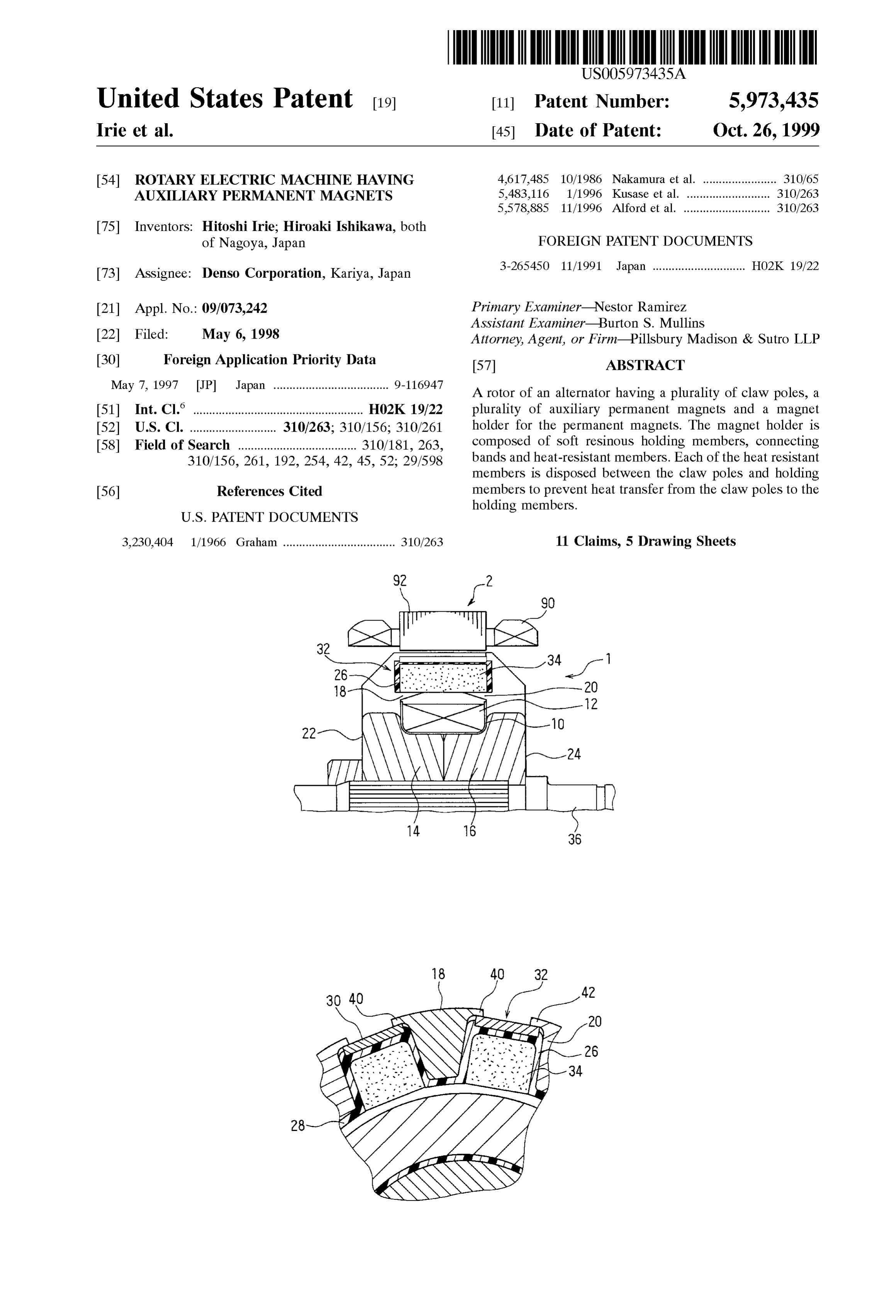
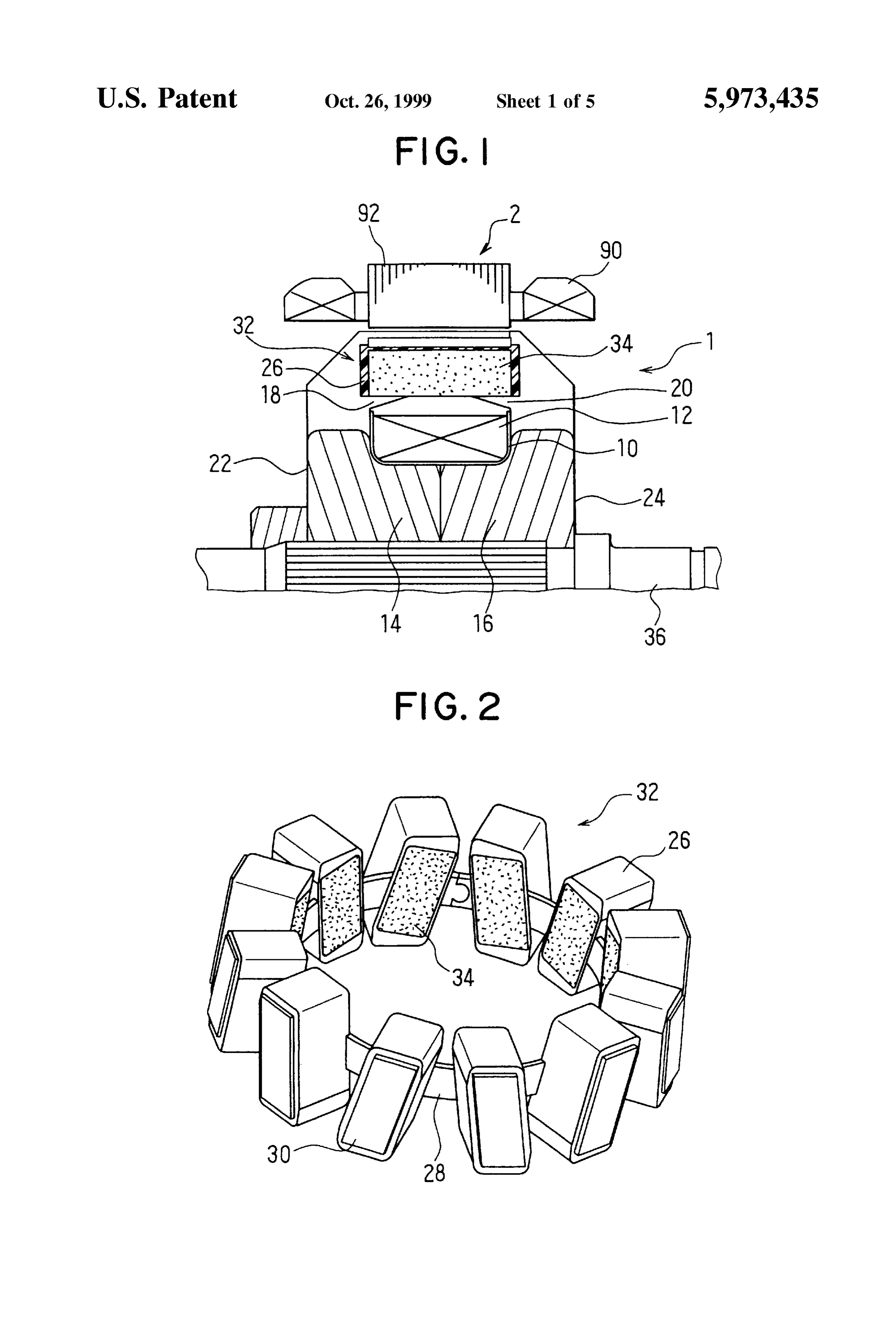
from Japanese Patent Application Hei 9-116947, filed on FIG. 1 is a fragmentary Sectional view illustrating a main May 7, 1997, the contents of which are incorporated herein portion of an alternator according to a first embodiment of by reference. the present invention;
BACKGROUND OF THE INVENTION FIG. 2 is a perspective view illustrating permanent mag 1. Field of the Invention nets in a magnet holder of the alternator according to the first embodiment;
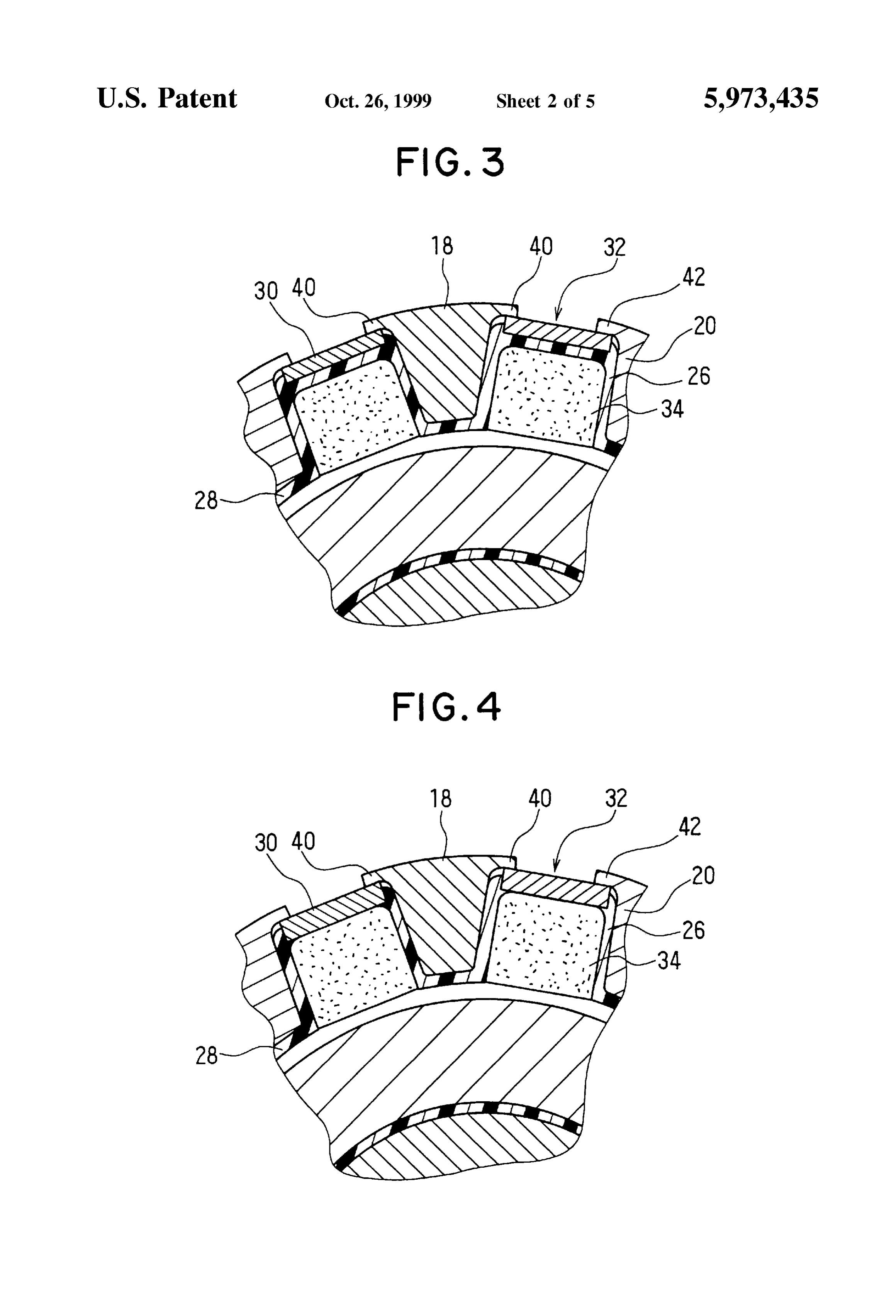
The present invention relates to a rotor having auxiliary FIG. 3 is an enlarged fragmentary Sectional view illus permanent magnets of a rotary electric machine, particularly, 15 trating the rotor of the alternator according to the first an alternator for a vehicle. embodiment;
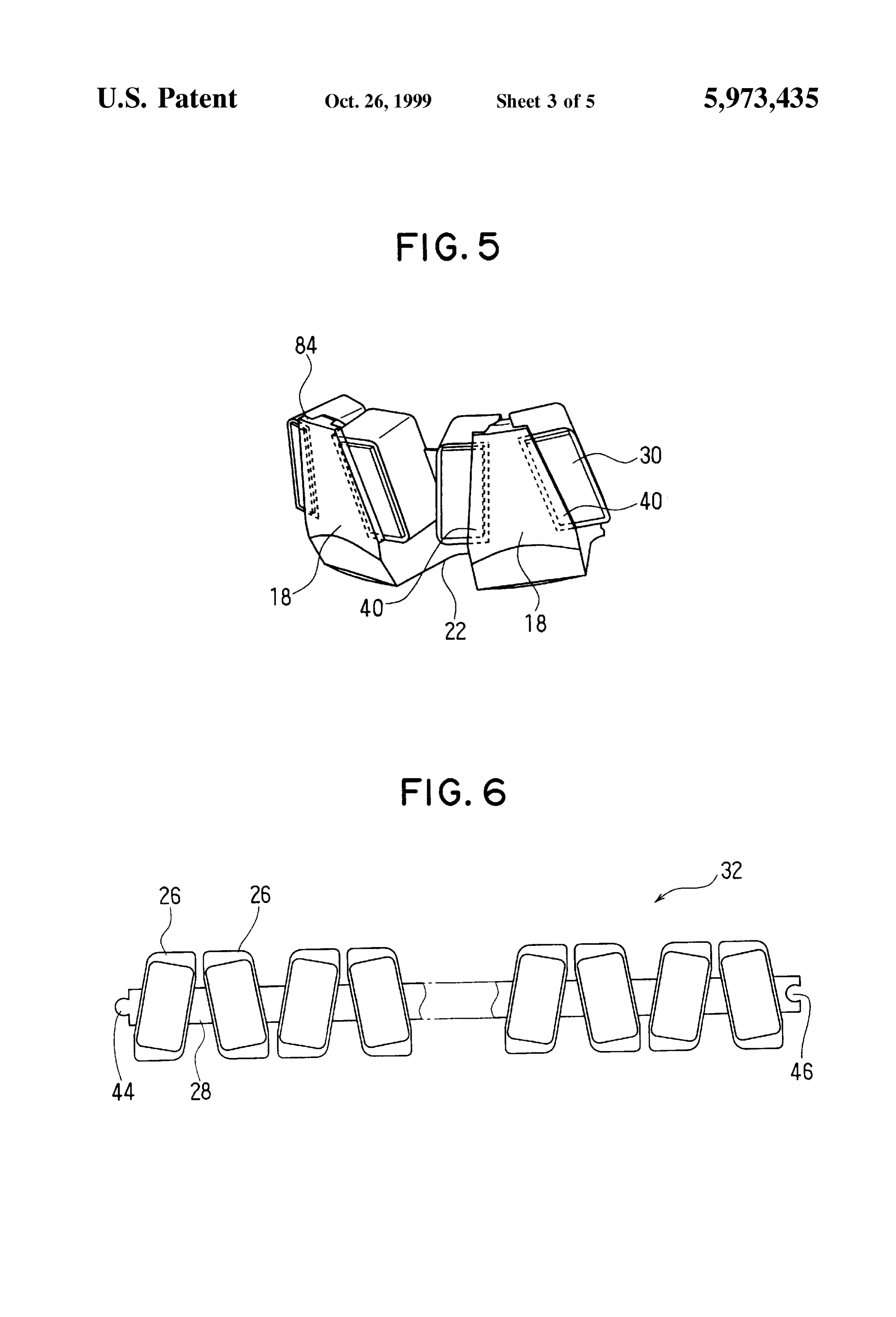
2. Description of the Related Art FIG. 4 is an enlarged fragmentary Sectional view illus A rotor of an alternator for vehicle is, generally, composed trating a variation of the rotor shown in FIG. 3; of a field coil and a plurality of claw poles. Recently, in order FIG. 5 is a fragmentary perspective view illustrating claw to increase the output power, auxiliary permanent magnets poles and the magnet holder assembled together. are installed between the claw poles to increase the field FIG. 6 is a plan view illustrating the magnet holder before magnetic flux.
it is assembled;
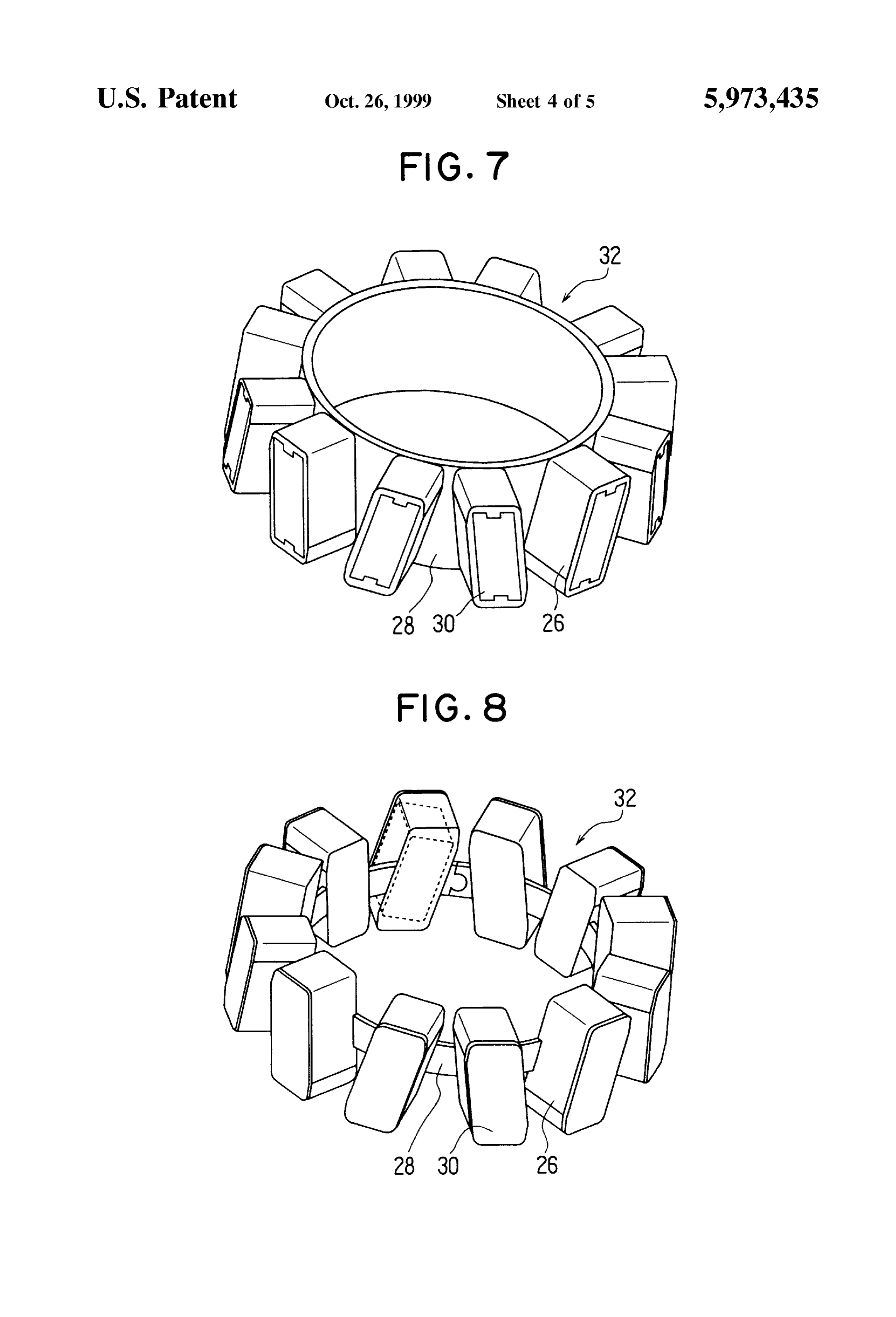
For example, JP-A-8-223882 discloses a rotor structure of FIG. 7 is a perspective view illustrating a variation of the Such an alternator. However, because the permanent mag 25 magnet holder of the alternator according to the first nets are fixed directly to the claw poles, it is difficult to hold embodiment;
the permanent magnets under a high rotation speed. In order to solve this problem, JP-A-7-123664 proposes another rotor FIG. 8 is a perspective view illustrating another variation Structure which is provided with a resinous magnet holder. of the magnet holder of the alternator according to the first The resinous magnet holder is molded with the permanent embodiment;
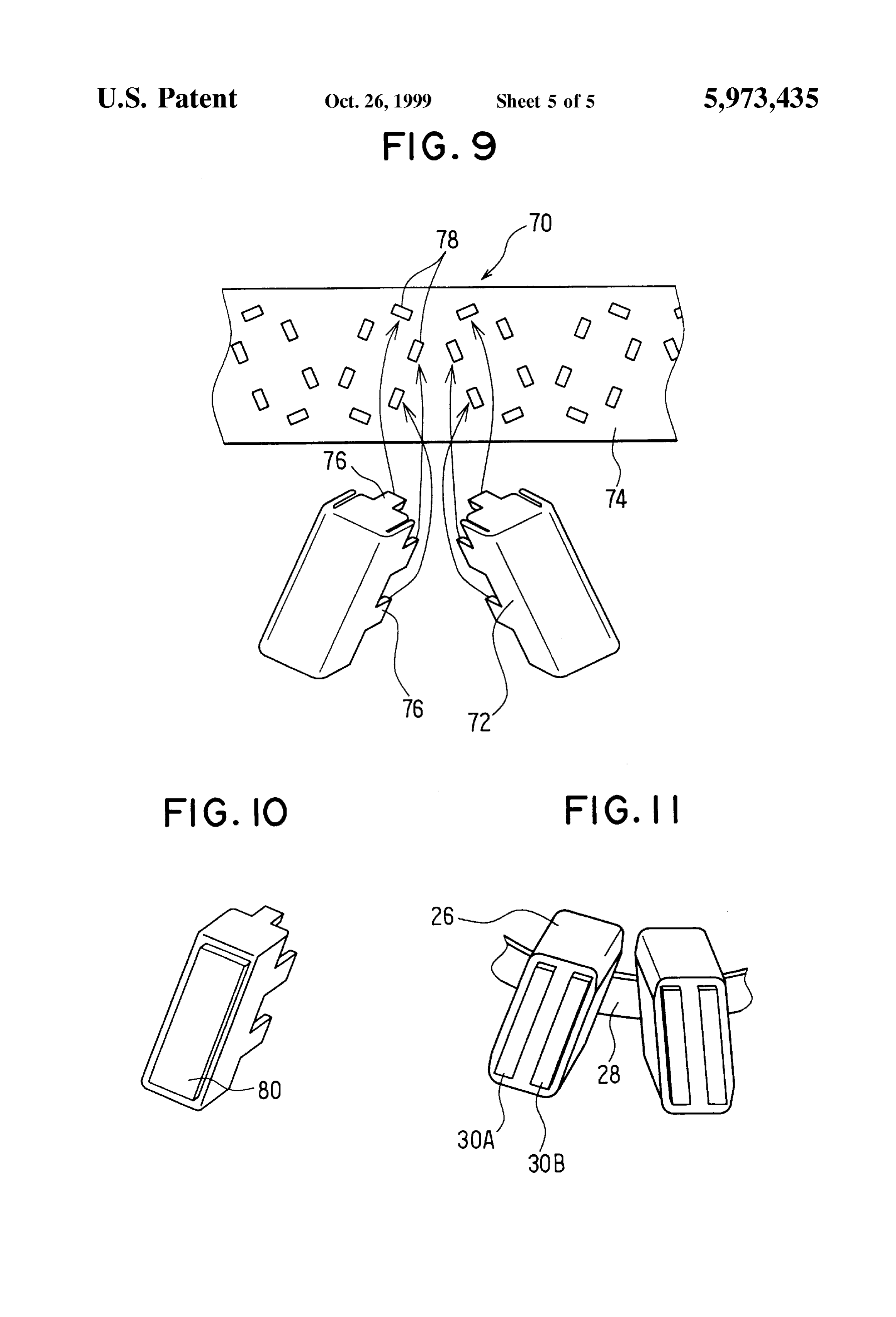
magnets and held between the claw poles. FIG. 9 is a fragmentary exploded view illustrating a AS the output power increases, temperature rise of the magnet holder of an alternator according to a Second alternator becomes higher. Particularly, temperature of the embodiment of the present invention;
claw pole Surfaces becomes significantly high because of FIG. 10 is a perspective view illustrating a variation of a increased eddy current as field magnetic flux is increased. 35 part of the magnet holder shown in FIG. 9; and This requires a resinous magnetic holder made of heat FIG. 11 a perspective view illustrating another variation resistant material, which is generally expensive. A metal of a part of the magnet holder shown in FIG. 9. magnetic holder is also expensive, because it must be made DETAILED DESCRIPTION OF THE from non magnetic metal Such as StainleSS Steel. PREFERRED EMBODIMENTS
(First Embodiment)
Therefore, a main object of the present invention to A rotor of an alternator according to a first embodiment of provide an improved and inexpensive rotor having a plural the present invention is described with reference to FIGS. ity of claw poles and auxiliary permanent magnets. 1-6.
Another object of the present invention is to provide a 45 Rotor 1 is composed of field coil 12 which is wound on rotor having an improved magnet holder. cylindrical bobbin 10, a pair of pole cores 22, 24, ring According to a feature of the present invention, a rotor for shaped magnet holder 32 for twelve permanent magnets 34 an electric machine has a plurality of claw poles, a plurality and Shaft 36. The pair of pole cores 22, 24, respectively, has of permanent magnets and a magnet holder, and the magnet center cores 14, 16 and six claw poles 18, 20 extending from holder comprises a plurality of magnet holding members, 50 respective center cores 14, 16, which is generally known. each of which has a heat-resistant member disposed at a Ring-shaped magnet holder 32 has twelve holding members limited portion between the claw pole and the permanent 26, twelve connecting bands 28 and twelve heat resistant magnet. Each of the claw poles has flange portions on the members 30. Holding members 26 and connecting bands 28 opposite Sides thereof for holding the heat-resistant mem are integrally formed of non-magnetic resinous material bers. Each of the holding members preferably has a portion 55 such as 46-nylon or polyphenylene sulfide (PPS). Heat disposed between the heat-resistant member and one of the resistant member 30 is made of nonmagnetic metal Such as permanent magnets. Each of the holding member can have Stainless Steel or aluminum, however, it can be made of a window for inserting one of the permanent magnets which resinous material heat resistant at 250° C. or higher. In such is covered by the heat-resistant member. a case, resinous heat resistant member 30 can be formed According to another feature of the present invention, a 60 integrally with holding members 26. Permanent magnets 34 rotor of a rotary electric machine has a plurality of claw are made of ferrite magnets, neodymium magnets or rare poles, a plurality of permanent magnets and a magnet holder, earth magnets. Stator 2, which is generally well known, is and the magnet holder comprises a plurality of heat resistant composed of stator coil 90 and stator core 92. magnet holding members and connecting members for con As illustrated in FIG. 2, each of holding members 26 of necting the magnet holding members. Each of the claw poles 65 magnet holder 32 has a box which has an opening and a can have flange portions on the opposite sides for holding concavity in which one of heat resistant members 30 is corresponding ones of the holding members. preSS-fitted. The opening of holding member 26 opens to
Page 8
radially inward So that permanent magnet 34 can be inserted In the foregoing description of the present invention, the through the opening and held by the bottom opposite the invention has been disclosed with reference to specific opening while rotor 1 is rotated. Heat resistant members 30 embodiments thereof. It will, however, be evident that can be fixed by a different way, Such as bonding or insert various modifications and changes may be made to the molding. If heat resistant member 30 is formed out of 5 Specific embodiments of the present invention without aluminum plate, the Surface thereof in contact with holding departing from the broader Spirit and Scope of the invention member 26 may be provided with a plurality of projections as Set forth in the appended claims. Accordingly, the descrip for reducing the contact area. Connecting bands 28 are tion of the present invention in this document is to be integrally formed with holding members 26. regarded in an illustrative, rather than restrictive, Sense. Each of claw poles 18, 20 has flanges 40, 42 on the What is claimed is:
circumferentially opposite sides thereof, and each of oppo site sides of heat resistant members 30 is disposed between 1. A rotor of a rotary electric machine comprising a pole one of holding members 26 and one of flanges 40, 42, so that core having a plurality of claw poles, a plurality of perma holding members 26 are not in direct contact with flange nent magnets each of which is disposed between consecutive portions 40, 42 as shown in FIG. 3. Thus, flanges 40, 42 hold ones of Said claw poles and a magnet holder for each of Said magnet holder 32 Securely against centrifugal force during 15 permanent magnets, wherein operation as shown in FIG. 5. Flanges 40, 42 also increases magnetic permeance between rotor 1 and Stator 2, thereby Said magnet holder comprises a plurality of magnet increasing the output power of the alternator. Heat resistant holding members and a plurality of heat-resistant mem member 30 can be placed in contact with permanent magnet bers made of a material more heat-resistant than Said 34 as shown in FIG. 4 to directly hold permanent magnet 34 holding member, and against centrifugal force during rotation of the rotor. Said heat resistant members have Surfaces respectively Thus, because magnet holder 32 is isolated by heat disposed between Said claw poles and Said holding resistant members 30 from claw poles, it can be made of soft members to thermally isolate Said holding members resinous material which is not expensive or necessarily heat from Said claw poles and to hold the same against resistant So that precise machining can be omitted. Perma 25 centrifugal forces applied thereto during operation. nent magnets 34 are magnetized to reduce the leakage flux between adjacent claw poles 18, 20. 2. The rotor as claimed in claim 1, wherein each of Said Ring-shaped magnet holder 32 is formed from a mold of claw poles has flange portions on the opposite Sides thereof chained holding members 26, and one of connecting bands for3.holding Said heat-resist members. The rotor as claimed in claim 1, wherein each of Said 28 extending from one end of the mold is provided with a heat-resistant member is disposed to hold one of Said projection 44 and another of connecting band 28 extending permanent magnets against centrifugal force. from the other end of the mold is provided with a concavity 4. The rotor as claimed in claim 1, wherein, 46 at the other end as shown in FIG. 6. Projection 44 is fitted into concavity 46 to form ring-shaped holder 32. The each of said holding members is provided with an opening connection can be Substituted by welding, bonding or the for inserting one of Said permanent magnets opening to like. 35 the radially outside, and
As a variant, ring-shaped magnet holder 32 is molded as Said opening is covered by Said heat-resistant member. illustrated in FIG. 7. Another variant of magnet holder 32 5. The rotor as claimed in claim 1, wherein having non-magnetic-metal heat-resistant member 30 is Said heat resistant member comprises a separate member. illustrated in FIG. 8. Each of holding members 26 has 6. The rotor as claimed in claim 1, wherein at least a opening opens radially outward, and the heat resistant mem 40 number of Said holding members are connected by band berS 30 are fixed to the openings after permanent magnets 34 members.
are inserted therethrough into holding members 26. 7. The rotor as claimed in claim 1, wherein each of Said (Second Embodiment) holding members defines a box in which one of Said per A rotor having auxiliary permanent magnets according to manent magnets is inserted.
a Second embodiment of the present invention is described 45 8. A rotor comprising a pole core having a plurality of with reference to FIG. 9. Magnet holder 70 is composed of claw poles, a plurality of permanent magnets each of which twelve box-like holding members 72 and connecting band is disposed between consecutive ones of Said claw poles and 74. Holding members 72 are made of nonmagnetic metal a magnet holder for each of Said permanent magnets, Such as StainleSS Steel or aluminum. Each of holding mem wherein berS has an opening and a plurality of projections 76 50 Said magnet holder comprises a plurality of heat resistant extending the periphery of the opening. Connecting band 74 magnet holding members and connecting members for is made of soft resinous material such as 46-nylon or PPS connecting Said magnet holding members, and and has a plurality of notches to which projections 76 are press-fitted. Other portions of the rotor are substantially the Said magnet holding members are made of a material SC. more heat-resistant than Said connecting members. In assembling, each of the permanent magnets is inserted 55 wherein 9. The rotor electric machine as claimed in claim 8, into corresponding one of holding members 72 through the opening thereof, and holding members 72 with the perma each of Said claw poles has flange portions on the opposite nent magnets therein are fixed to connecting band 74 by Sides thereof for holding corresponding ones of Said projections 76 press-fitted into notches 78. Thereafter, con 60 holding members.
necting band 74 is formed into a ring. 10. The rotor as claimed in claim 8, wherein said con A portion of each of holding members 72 can be made of necting member is made of a Softer material than Said non-heat-resistant resin. In this case, a portion 80 in contact magnet holding members.
with the claw pole is made of heat resistant material as 11. The rotor as claimed in claim 8, wherein each of Said illustrated in FIG. 10. The portion 80 can be divided into two holding members defines a box in which one of Said per pieces 30A, 30B as shown in FIG. 11. In this case two pieces 65 manent magnets is inserted.
30A, 30B can be made of inexpensive material such as iron or Steel. k k k k k
Provenance
- Collection
- Cited prior art
- Original PDF
- patentimages.storage.googleapis.com →
- Filed
- 1998-05-06
- Pages
- 8
- Method
- pdftotext (the PDF's own text layer) + pdftoppm 300dpi page scans
- Source
- Google Patents bibliographic record
- Granted
- 1999-10-26
- Inventors
- Hitoshi Irie; Hiroaki Ishikawa; Denso Corp
- Transcribed from
- patentimages.storage.googleapis.com →