patent · US5302876
Rotor of synchronous motor
12 April 1994
Page 1 — bibliographic record
United States Patent (19) 11) Patent Number: 5,302,876 Iwamatsu et al. (45) Date of Patent: Apr. 12, 1994 54) ROTOR OF SYNCHRONOUS MOTOR 60-13456 1/1985 Japan.
(75) Inventors: Noboru Iwamatsu; Syougo Higashi, 62-233053 10/1987 Japan. both of Yamanashi, Japan 63-124072 8/1988 Japan.
73) Assignee: Fanuc, Ltd., Yamanashi, Japan Primary Examiner-R. Skudy 21) Appl. No.: 949,855 Attorney, Agent, or Firm-Nikaido, Marmelstein, Murray & Oram 22 PCT Filed: Apr. 2, 1992 57. ABSTRACT (86). PCT No.: PCT/JP92/00408 A rotor of a synchronous motor incorporates a rotor S371 Date: Nov. 20, 1992 core assembly 14 including a rotor core 10 formed by a S 102(e) Date: Nov. 20, 1992 lamination of ferrosilicone plates and a plurality of per manent magnets 12 arranged on the outer periphery of (87) PCT Pub. No.: WO92/17931 the rotor core 10. The rotor core assembly 14 is formed PCT Pub. Date: Oct. 15, 1992 by coaxially connecting a plurality of rotor core units 18 in an axial direction. Each of the rotor core units 18 (30) Foreign Application Priority Data has an axial dimension enabling the permanent magnets Apr. 2, 1991 (JP) Japan. 3-69823 12 to be magnetized by a normal size magnetizer. Each 51 Int. Cl. ............................................. H02K 21/12 of the rotor core units 18 includes an auxiliary rotor 52 U.S.C. ...................................... 310/156; 310/42; core 10' formed by a lamination of magnetic thin plates 310/112; 310/162; 310/217; 310/261 and a plurality of auxiliary permanent magnets 12' 58) Field of Search ................. 310/156, 217, 42, 162, arranged and affixed on the outer periphery of the auxil 310/112, 114, 181,261, 91,263 iary rotor core 10' at predetermined equal pitches in the
circumferential direction. Each of the auxiliary perma nent magnets 12" has a configuration of an identical
4,642,502 2/1987 Carpenter ........................... 310/156 trapezoid in a plan view. The auxiliary rotor core 10' 4,714,852 12/1987 Kawada .............................. 310/156 includes a plurality of through holes 26 axially extend 4,792,713 12/1988 Bush .................................... 310/217 ing with common diameters at the positions of equal 4,795,936 l/1989 Crossetto ............................ 310/156 intervals on the predetermined radius circumference. 5,140,211 8/1992 Uchida ..... ... 310/156 Four spring pins 28 are inserted alternately into the 5,157,297 10/1992 Uchida ..... ... 310/261 through holes 26. The spring pins 28 integrally hold 5,200,662 4/1993 Tagami ................................ 310/261 together a lamination of thin magnetic plates of the
FOREIGN PATENT DOCUMENTS auxiliary rotor core 10'.
58-56401 4/1983 Japan. 6 Claims, 3 Drawing Sheets
s Seta SS25 as era
alter
Page 2
Drawing sheet — no readable text.
Page 3
Drawing sheet — no readable text.
Page 4
Drawing sheet — no readable text.
Page 5
wherein the rotor core assembly is formed by coaxially
ROTOR OF SYNCHRONOUS MOTOR connecting a plurality of rotor core units in an axial direction. In this rotor, each of the rotor core units
TECHNICAL FIELD includes a generally cylindrical auxiliary rotor core formed by a lamination of thin magnetic plates and
The present invention relates to a rotor of a synchro 5 constituting nous motor which comprises a rotor core assembly mutually connecting the rotor core of the rotor core assembly by including a generally cylindrical rotor core formed by a the auxiliary rotor core in the axial lamination of thin magnetic plates and a plurality of direction, fastening means for integrally fastening and permanent magnets arranged and affixed on the periph 10 holding a laminated construction of the auxiliary rotor ery of the rotor core at predetermined equal pitches in core, a plurality of auxiliary permanent magnets ar a circumferential direction, and a rotating shaft coaxi ranged and affixed on a periphery of the auxiliary rotor ally passing through the rotor core assembly and inte core at predetermined equal pitches in the circumferen grally affixed to the rotor core. More particularly, the tial direction and constituting the permanent magnets of present invention relates to a rotor of a synchronous the rotor core assembly by mutually connecting the motor of which a rotor core assembly can be separated 15 auxiliary permanent magnets in the axial direction, into a plurality of rotor core units in order to facilitate aligning means for aligning the auxiliary permanent magnetizing of the permanent magnets in the manufac magnets between the rotor core units connected to each turing process of a large-size electric motor. other so as to form continuous bound surfaces located in
the circumferential direction of the permanent magnets of the rotor core assembly at the time of mutual connec
In a rotor of a synchronous motor which includes a tion in the axial direction, and fixing means for fixing plurality of permanent magnets for forming magnetic the rotor core units to be connected to each other. poles, a rotor having a rotor core assembly including a Therefore, the rotor enables the rotor core assembly to generally cylindrical rotor core formed by a lamination be formed after magnetizing the auxiliary permanent of thin magnetic plates and a plurality of permanent 25 magnets individually for each of the rotor core units. magnets arranged and affixed on the periphery of the According to the preferred embodiment of the pres rotor core at predetermined pitches in a circumferential ent invention, the rotor is also provided with fastening direction, is known. In this type of rotor, a magnetizing means of the rotor core unit comprise fastening rod process of the permanent magnets has been generally members which are inserted into a plurality of through performed for each of a simple permanent magnet mate 30 holes formed axially in the auxiliary rotor core in an rial, individually, before incorporating the same into the rotor core, or for all permanent magnet materials after elastically deformed fashion and come into contact with walls of the through holes with a high pressure by their affixing them at predetermined positions on the rotor elastic restoring force so as to frictionally hold the lami COe.
However, these conventional methods of magnetiz 35 nation of the magnetic thin plates together. Further, the aligning means of the rotor core unit ing have had problems as described below when the may comprise projections formed on and projecting electric motor must be increased in size. First, in the from at least one axial end face of the auxiliary rotor method of magnetizing a simple permanent magnet core and depressions formed in an end face of another material, since the size of the permanent magnet mate rotor core unit to be connected opposite to the axial end rial is also increased following the scaling up of a motor, it becomes difficult to correctly affix large and heavy face so as to receive the projections. Moreover, the auxiliary permanent magnets of the permanent magnets at predetermined positions on a rotor core when the permanent magnets are affixed to rotor core unit may include circumferential bound sur the rotor core after being magnetized, and this problem faces inclined in a predetermined direction in relation to is increased by the repelling magnetic force between the 45 an axis and lines of symmetry extending parallel to the adjoining magnets. Further, in the method of magnetiz axis. Alternatively, the auxiliary permanent magnets of the ing all permanent magnet materials after affixing them on the rotor core, a large-size magnetizer becomes nec rotor core unit may include circumferential bound sur faces inclined in a constant direction in relation to the essary in accordance with the scaling up of the motor, axis.
and manufacture of such a magnetizer would not be 50 easy. Accordingly, the method may be considered of Further, the fixing means of the rotor core unit may using a relatively small normal magnetizer for magne comprise an adhesive for adhesively fixing end faces of tizing the same pole part of the permanent magnet mate each rotor core unit to be connected to each other. rials affixed on the rotor core and repeating this to iaryFurthermore, the rotor is also provided with auxil permanent magnets of the rotor core unit including magnetize the overall magnet materials, but this method 55 is not desirable since the leakage flux will have a detri circumferential bound surfaces inclined in a predeter mental effect on the magnets other than the magnetized mined direction in relation to an axis and lines of sym part during the magnetization of each part. metry extending parallel to the axis and affixed to the periphery of the auxiliary rotor core so as to arrange
DISCLOSURE OF THE INVENTION with parallel the adjoining bound surfaces of the auxil The object of the present invention is to provide a iary permanent magnets adjoined in the circumferential rotor of a synchronous motor wherein the magnetiza direction, the fastening means of the rotor core unit tion of a plurality of permanent magnet materials affixed comprise fastening rod members inserted into some of a on the periphery of a rotor core can be easily performed plurality of through holes formed axially in the auxiliary even with a large-size electric motor. 65 rotor core in an elastically deformed fashion and com To accomplish the above object, the present inven ing into contact with walls of the through holes with a tion provides a rotor of a synchronous motor, in the high pressure by their elastic restoring force so as to type as stated at the beginning of this description, frictionally hold the lamination of the magnetic thin
Page 6
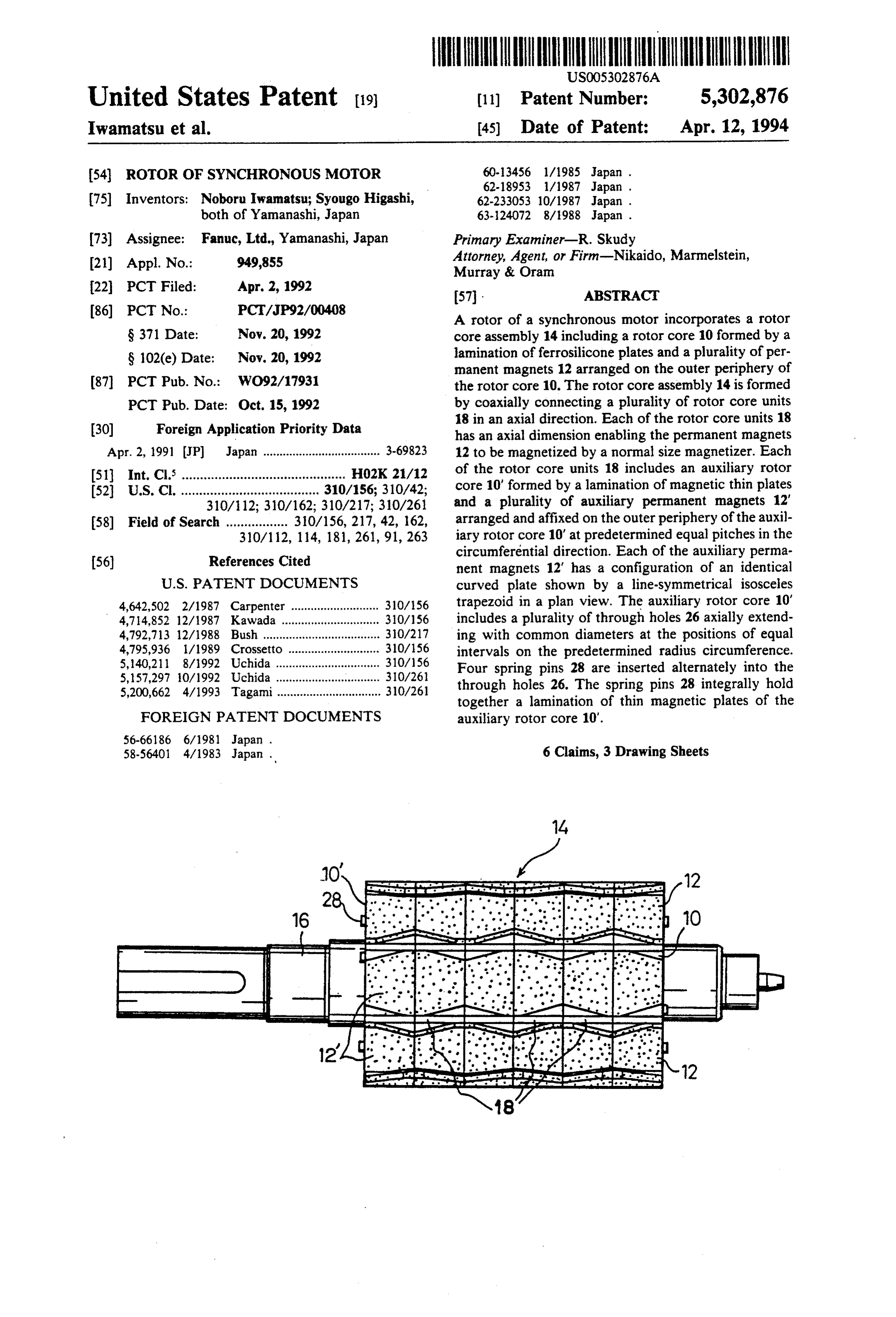
plates together, the aligning means comprise projected assembly 14 and integrally affixed to the center of the end portions of the fastening rod members projected rotor core 10. The rotor core assembly 14 is formed by from the two axial end faces of the auxiliary rotor core coaxially connecting a plurality of rotor core units 18 and the remaining through holes receiving none of the (six in the illustrated embodiment) in an axial direction. fastening rod members, the through holes receiving the 5 Each of the rotor core units 18 has an axial dimension fastening rod members and the through holes receiving enabling the permanent magnets 12 to be magnetized by none of the fastening rod members are arranged in a a normal size magnetizer.
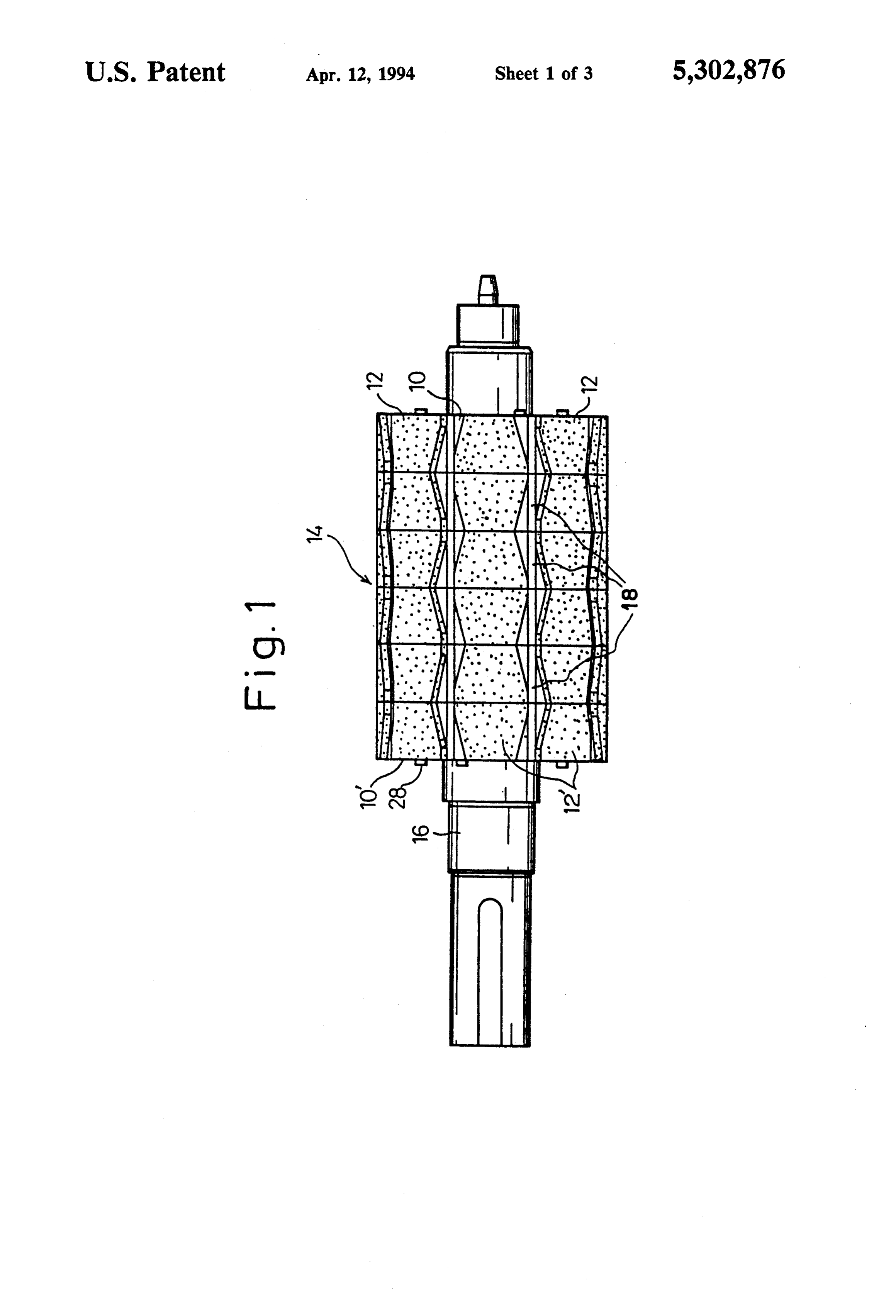
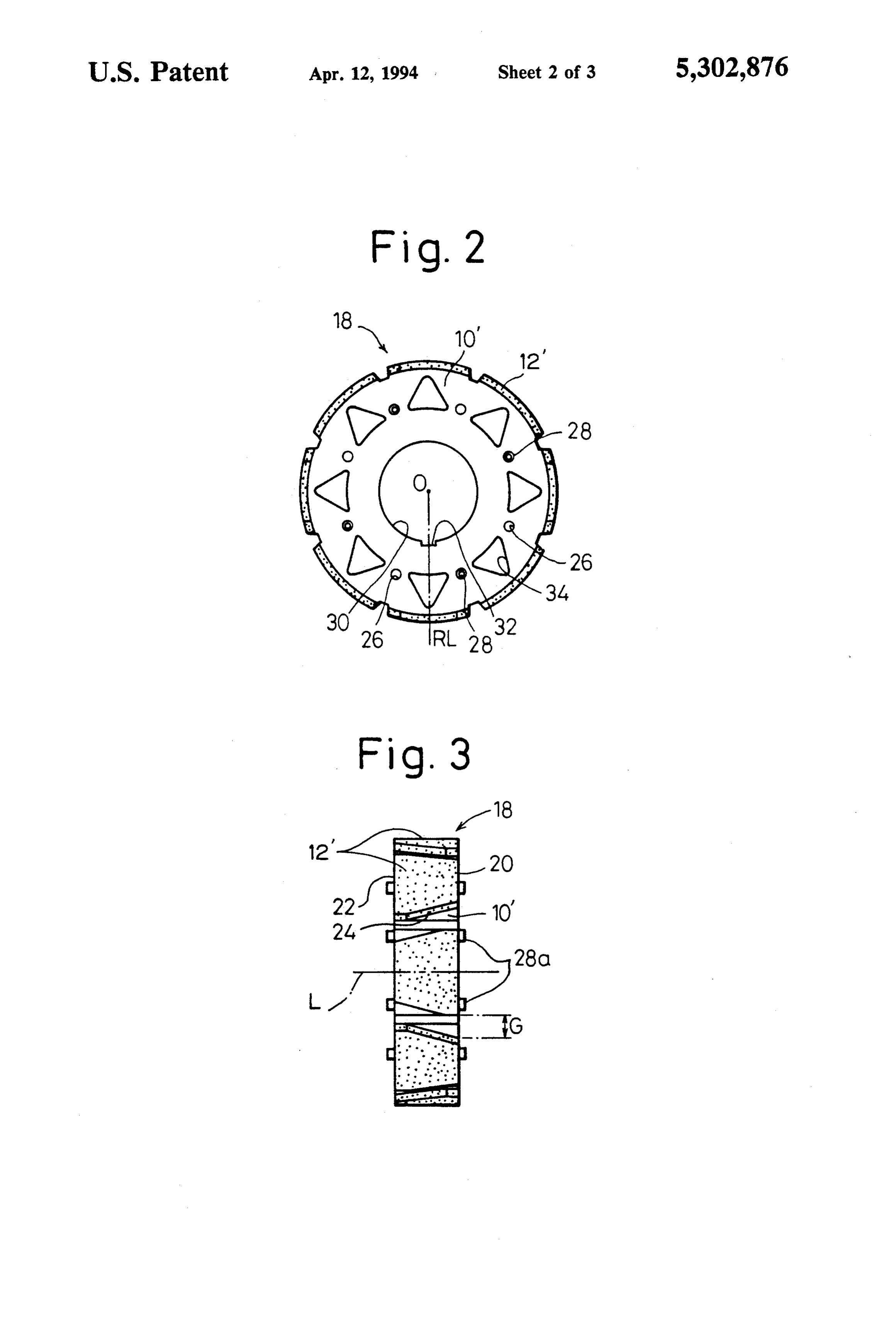
line-symmetrical relation to at least one radial line of the As shown in FIGS. 2 and 3, each of the rotor core auxiliary rotor core crossing the lines of symmetry of units 18 includes a generally cylindrical auxiliary rotor the auxiliary permanent magnets, and the rotor core 10 core 10' formed by a lamination of thin magnetic plates assembly is formed by connecting a pair of the rotor and constituting the rotor core 10 of the rotor core core units, being coaxially connected in the axial direc assembly 14 by mutually connecting the auxiliary rotor tion, in a mutually inverted relationship and in a condi core 10' in the axial direction, and a plurality of auxil tion for mutually aligning the radial lines as datum of iary permanent magnets 12' (eight in the illustrated arrangement of the through holes. 15 embodiment) arranged and affixed on the outer periph In the rotor core with the above constitution accord ery of the auxiliary rotor core 10' at predetermined ing to the present invention, the auxiliary rotor core as equal pitches in the circumferential direction and con a laminate of the magnetic thin plates is integrally held stituting the permanent magnets 12 of the rotor core by fastening action of the fastening means. Thus, the assembly 14 in the same manner. Each of the auxiliary magnetization of the auxiliary permanent magnets ar 20 permanent magnets 12" has a configuration of an identi ranged and affixed on the periphery of the auxiliary cal curved plate shown by a line-symmetrical isosceles rotor core can be individually performed for each of the trapezoid in a plan view. Each of the auxiliary perma rotor core units. Therefore, a conventionally available nent magnets 12' is affixed on the outer periphery of the normal size magnetizer can be used. After completing, auxiliary rotor core 10' in such a manner that a line of in this way, the magnetizing process for the auxiliary 25 symmetry L of the auxiliary permanent magnet 12' is permanent magnets of each of the rotor core units, the arranged parallel to the longitudinal direction of the rotor core units are axially connected to each other. At rotor core unit 18, i.e., the laminating direction of the this time, between the adjoining rotor core units, the magnetic thin plates of the auxiliary rotor core 10'. aligning means mutually align each of the auxiliary Further, the auxiliary permanent magnets 12" adjoining permanent magnets to connect the like poles thereof 30 in the circumferential direction are disposed so as to and continue the bound surfaces located in the circum alternatively invert top sides 20 and bottom sides 22 ferential direction of the permanent magnets of the thereof. Therefore, oblique sides 24, forming the cir rotor core assembly which have been connected. cumferentiai bound surfaces of each of the auxiliary Therefore, when incorporated in an electric motor, a permanent magnets 12' adjoining in the circumferential torque ripple caused by the irregular arrangement, par 35 direction, extend parallel to each other so as to form a ticularly the discontinuity of the bound surfaces located constant gap G therebetween.
in the circumferential direction, of the permanent mag The reason that the configuration of the auxiliary nets, can be prevented. permanent magnets 12' is a trapezoid in a plan view as shown in the above embodiment is to obliquely arrange
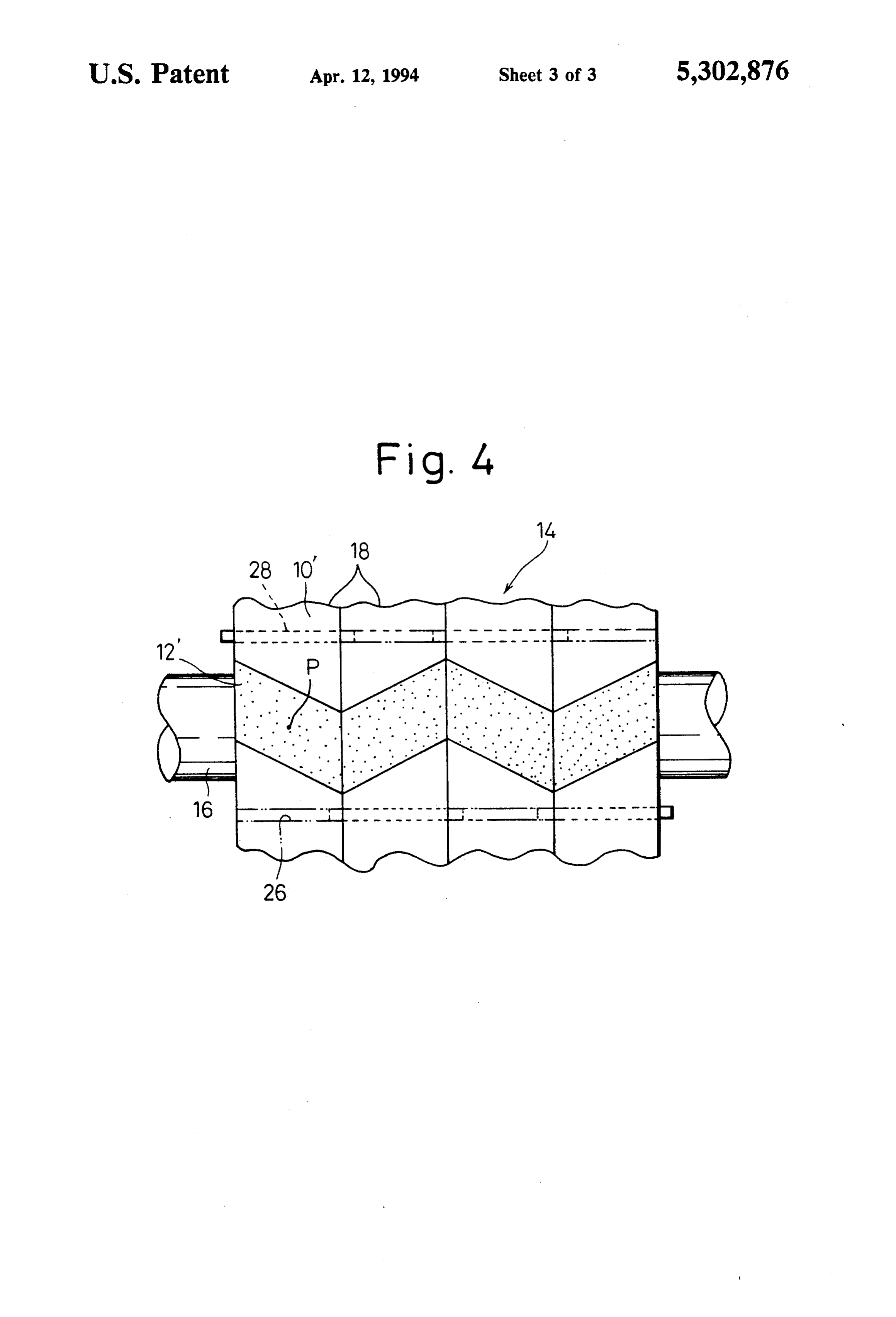
BRIEF DESCRIPTION OF THE DRAWINGS 40 the two circumferentially bound surfaces of each of the The foregoing and other objects, features, and advan permanent magnets 12 in relation to an axis when the tages of the present invention will be described with rotor core assembly 14 is assembled. It is known that, by relation to the embodiments shown in the accompany such a configuration of the permanent magnets 12, ing drawings, in which; changing characteristics of a flux density in a gap be FIG. 1 is a side view of a rotor of a synchronous 45 tween the rotor and an exciting pole of a stator (not motor according to first embodiment of the present shown) during rotation of the rotor are improved from invention; a stepped sharp change to a gradual change, and thus FIG. 2 is a front view of a rotor core unit constituting the torque ripple is reduced.
the rotor of FIG. 1; As shown in FIG. 2, the auxiliary rotor core 10' of the FIG. 3 is a side view of the rotor core unit of FIG. 2; 50 rotor core unit 18 includes a plurality of through holes and 26 (eight in the illustrated embodiment) axially extend FIG. 4 is a partial side view of a rotor according to ing with common diameters at the positions of equal another embodiment of the present invention. intervals on the predetermined radial circumference in relation to the center of revolution 0. Each of the
BEST MODE OF CARRYING OUT THE 55 through holes 26 is located at a line-symmetrical posi INVENTION tion in relation to eight radial lines RL of the auxiliary The present invention will be described in more detail rotor core 10', each crossing the line of symmetry L of based on the embodiment thereof referring to the ac the auxiliary permanent magnet 12'. Four spring pins 28 companying drawings. are inserted alternately into the through holes 26. The Referring to FIG. 1, a rotor of a synchronous motor 60 spring pin 28 is a known fastening pin with a C-shaped according to first embodiment of the present invention cross section made of spring steel and acts as a fastening comprises a rotor core assembly 14 including a gener means of the present invention to integrally hold a lami ally cylindrical rotor core 10 formed by a lamination of nation of magnetic thin plates of the auxiliary rotor core thin magnetic plates, such as ferrosilicone plates and a 10'. Further, two ends of the spring pins 28 are pro plurality of permanent magnets 12 arranged and affixed 65 jected to some degree from two end faces of the auxil on the outer periphery of the rotor core 10 at predeter iary rotor core 10", and the projected ends 28a are fitted mined pitches in a circumferential direction, and a rotat in the through holes 26, which do not have spring pins ing shaft 16 coaxially passing through the rotor core 28, of the auxiliary rotor core 10' of another rotor core
Page 7
unit 18 as mentioned below, when the rotor core assem magnetic plates forming the auxiliary rotor core 10 bly is assembled. Therefore, the spring pins 28 act as need to be prepared, therefore the above embodiment is aligning means during connecting of the rotor core unit a preferred construction in terms of manufacturing cost 18, as mentioned below. Furthermore, the spring pins in comparison with a construction including the inde 28 are preferably disposed at equal intervals in the cir pendent fastening means and aligning means, e.g., in cumferential direction, as the illustrated embodiment, in cluding mutually engageable projections and depres consideration of a dynamic balance during the rotation sions (not shown in the drawings) formed on two end of the rotor. faces of the auxiliary rotor core 10' independently of the The auxiliary rotor core 10' also includes an insertion spring pins 28.
hole 30 formed axially through the center thereof, in 10 Furthermore, the configuration of the auxiliary per which the rotating shaft 16 is closely fitted. One portion manent magnets 12' is not restricted to the above line in a periphery of the insertion hole 30 is provided with symmetrical form and may be of, e.g., a parallelogram a key groove 32 engageable with a key portion (not in a plan view, as shown in FIG. 4 as a second embodi shown) on the rotating shaft 16, and, by such a mutual ment. In this case, a radial line joining the center P of engagement therebetween, a torque is transmitted from 15 the parallelogram of the auxiliary permanent magnet 12' the auxiliary rotor core 10' to the rotating shaft 16. In and the center of rotation O of the rotor core unit 18 is this embodiment, the key groove 3225 is arranged on dealt with as equivalent to the aforementioned radial the aforementioned radial line RL crossing the line of symmetry L of one auxiliary permanent magnet 12" of lineThe RL.
the rotor core unit 18. The auxiliary rotor core 10' is 20 pins 28number are not of the through holes 26 and the spring restricted to the above, and, e.g., two also provided with a plurality of holes 34 for reducing a spring pins 28 may be disposed within four through moment of inertia.
The rotor core unit 18 with the above constitution holes 26. In this case, the through holes 26 are arranged has, as previously stated, an axial dimension enabling at equal intervals on the radial lines RL, on which the key groove does not lie, among the aforementioned the auxiliary permanent magnets 12' to be magnetized 25 radial lines RL.
by a normal size magnetizer, and thus the magnetization can be individually performed for each rotor core unit As clear from the above explanation, according to the 18. The rotor core assembly 14 is formed by coaxially present invention, the rotor core of the rotor of the connecting a plurality of rotor core units 18 which have synchronous motor is constructed by coaxially connect been completely magnetized in this way. 30 ing a plurality of rotor core units in the axial direction When the rotor core assembly 14 is assembled, a pair and incorporating the rotor core units by fastening of rotor core units 18 to be axially connected are con means, and includes aligning means for aligning the nected in a mutually inverted condition. At this time, if arrangement of the permanent magnets when incorpo the rotor core units 18 are connected so as to continue rated, and thus the magnetizing process can be per the insertion holes 30 thereof and match the radial lines 35 formed individually on each rotor core unit and the RL, on which the key grooves 32 lie, to align the key accuracy for assembling the rotor core assembly can be grooves 32 in the axial direction, the projected ends 28a maintained at a high level. Therefore, the magnetization of the spring pins 28 and the hollow through holes 26 of a plurality of permanent magnets affixed on the pe face and can be fitted to each other, between the rotor riphery of the rotor core can be easily and precisely core units 18. Further, the auxiliary permanent magnets performed even with a large-sized electric motor, and 12' axially adjoined between the rotor core units 18 scaling up of the electric motor is further facilitated. have their lines of symmetry L. lying on the common We claim:
line and the top sides 20 or the bottom sides 22 of each 1. A rotor core assembly for a rotor of a synchronous of the auxiliary permanent magnets 12" face each other. motor, comprising:
Therefore, as shown in FIG. 1, the permanent magnets 45 a plurality of rotor core units coaxially connected to 12 of the rotor core assembly 14 are formed so as to each other in an axial direction, each of said plural mutually continue the oblique sides 24 of the auxiliary ity of rotor core units including a cylindrical auxil permanent magnets 12", therefore the fear of detrimen iary rotor core formed from a lamination of thin tally effecting the change of the flux density during magnetic plates, rotation in the gap between the rotor and the stator (not 50 fastening means for integrally fastening and holding shown) is eliminated, and thus the torque ripple caused the lamination of the auxiliary rotor cores, by the change of the flux density is prevented. a plurality of auxiliary permanent magnets affixed on In this way, a plurality of rotor core units 18 (eight in an outer periphery of each auxiliary rotor core at the illustrated embodiment) are correctly connected in predetermined equal pitches in a circumferential the axial direction by fitting the projected ends 28a of 55 direction, each of the plurality of auxiliary rotor the spring pins 28 and the hollow through holes 26 cores being individually magnetized with said aux between the rotor core units 18. Then, the rotor core iliary permanent magnets affixed thereto, assembly 14 is formed by fixing the connected portions aligning means for aligning the plurality of auxiliary between the rotor core units 18 by fixing means, such as permanent magnets between said plurality of rotor an adhesive, and the rotating shaft 16 is closely fitted in 60 the continued insertion hole 30, and thereby the rotor of core units connected to each other so as to align the present invention is constructed. bound surfaces located in the circumferential direc In the embodiment explained above, in the rotor core tion such that aligned auxiliary permanent magnets unit 18, the through holes 26 and the spring pins 28 constitute a plurality of permanent magnets extend cooperate with each other to act as the fastening means 65 ing along an axial direction on an outer periphery for fastening the lamination of each unit and the align of said rotor core assembly, and ing means for aligning the rotor core units 18. Accord fixing means for fixing said plurality of rotor core ing to such a construction, only one type of the thin units so as to be connected to each other; and
Page 8
a rotating shaft coaxially passing through said plural 6. A rotor core assembly as set forth in claim 1, ity of coaxially connected rotor core units and wherein the auxiliary permanent magnets of each of integrally affixed thereto, the aligning means of said plurality of rotor core units include circumferential each of said plurality of rotor core units include bound surfaces inclined in a predetermined direction in projections formed on and projecting from at least 5 relation to an axis and lines of symmetry extending one axial end face of each of the plurality of parallel to the axis, and are affixed to the periphery of auxiliary rotor cores, and depressions formed in an the auxiliary rotor core so as to be arranged parallel opposing end face of an adjacent rotor core unit with adjoining bound surfaces of the auxiliary perma for alignably receiving the projections. nent magnets adjoined in the circumferential direction, O the fastening means includes fastening rod members 2. A rotor core assembly as set forth in claim 1, wherein the fastening means of said rotor core units which are inserted into some of a plurality of includes fastening rod members which are inserted into through holes defined axially in each of the plural a plurality of through holes defined axially in each of ity of auxiliary rotor cores, the fastening rod mem the plurality of auxiliary rotor cores, the fastening rod 15 bers being elastically deformable so as to come into members being elastically deformable so as to come into frictional contact with walls of the through holes frictional contact with walls of the through holes by by their elastic restoring force, their elastic restoring force. the aligning means includes projected end portions of 3. A rotor core assembly as set forth in claim 1, the fastening rod members projected from two wherein the auxiliary permanent magnets of each of 20 axial end faces of each of the auxiliary rotor cores said plurality of rotor core units include circumferential with remaining through holes receiving none of the bound surfaces inclined in a predetermined direction in fastening rod members, the through holes receiving relation to an axis and lines of symmetry extending the fastening rod members and the through holes parallel to the axis. receiving none of the fastening rod members being arranged in a line-symmetrical relation to at least 4. A rotor core assembly as set forth in claim 1, one radial line of the auxiliary rotor cores crossing wherein the auxiliary permanent magnets of each of lines of symmetry of the auxiliary permanent mag said plurality of rotor core units include circumferential nets, and bound surfaces inclined in a constant direction in rela said rotor core assembly is formed by connecting a to to an axis.
axis 30 pair of said rotor core units, being coaxially con 5. A rotor core assembly as set forth in claim 1, nected in the axial direction, in a mutually inverted wherein the fixing means of each of said plurality of relationship and in a condition for mutually align rotor core units includes an adhesive for adhesively ing the radial lines as datum of arrangement of the fixing opposing end faces of adjacent rotor core units so through holes.
as to be connected to each other. 35 a
Provenance
- Collection
- Cited prior art
- Original PDF
- patentimages.storage.googleapis.com →
- Filed
- 1992-04-02
- Pages
- 8
- Method
- pdftotext (the PDF's own text layer) + pdftoppm 300dpi page scans
- Source
- Google Patents bibliographic record
- Granted
- 1994-04-12
- Inventors
- Noboru Iwamatsu; Syougo Higashi; Fanuc Corp
- Transcribed from
- patentimages.storage.googleapis.com →