patent · US5670838
Electrical machines
23 September 1997
Page 1 — bibliographic record
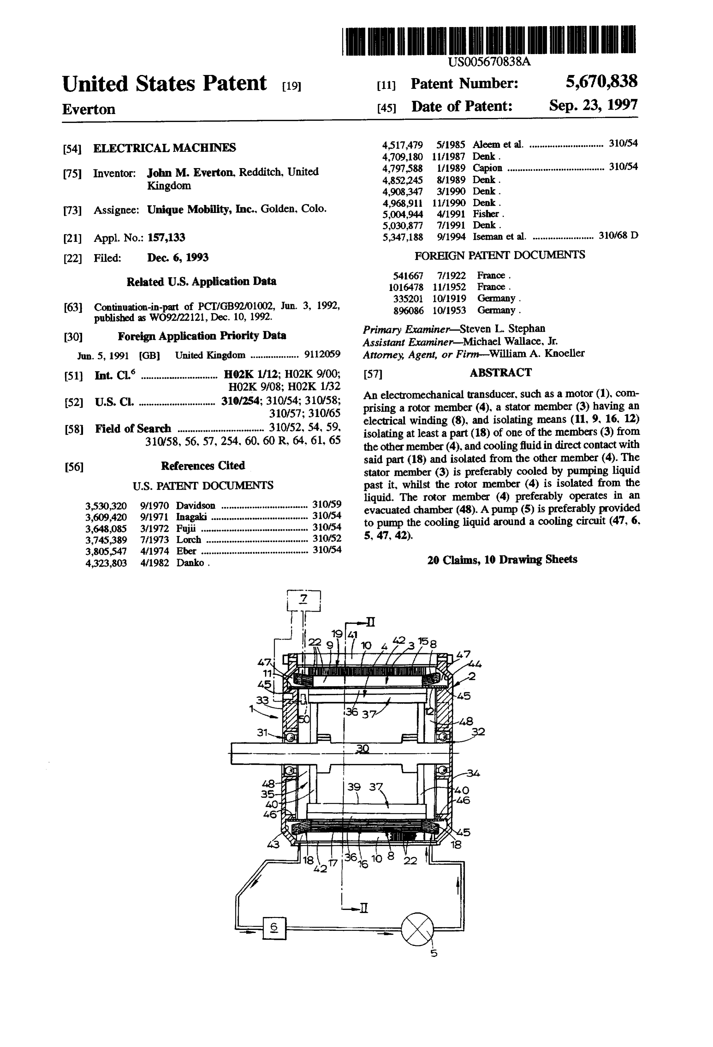
United States Patent (19) 11) Patent Number: 5,670,838 Everton (45) Date of Patent: Sep. 23, 1997 54 ELECTRICAL MACHINES 4,517,479 5/1985 Aleem et al. ............................. 310/54
75 Inventor: John M. Everton, Redditch, United 4,797,588 1/1989 Capion ..................................... 31.0/54 Kingdom 4.852,245 8/1989 Denk.
renaa & Tra t 4,968,911 11/1990 Denk.
73) Assignee: Unique Mobility, Inc.. Golden, Colo. 5,004,944 4/1991 Fisher.
(21) Appl. No.: 157,133 5,347,188 9/1994 Iseman et al. ........................ 310/68 D 22 Filed: Dec. 6, 1993 FOREIGN PATENT DOCUMENTS Related U.S. Application Data 541667 7/1922 France.
63 Continuation-in-part of PCT/GB92/01002, Jun. 3, 1992, 896086 10/1953 G y.
d O O Primary Examiner-Steven L. Stephan
O Application pplication Priority D
Priority Data ry Examiner-Michael Wallace,
Jun. 5, 1991 GB United Kingdom ................... 9112059 Attorney, Agent, or Firm-William A. Knoeller (51) Int. Cl. ................. H02K 1/12; H02K9/00; 57 ABSTRACT
(52) U.S. Cl. .......................... 310,254; 31054; 310.58.
An electromechanical transducer, such as a motor (1), com prising a rotor member (4), a stator member (3) having an 58 Field of Search ............................ losso, electrical winding (8), and isolating means (1,9,1612) 310/58, 56, 57,254, 60, 60 R 64 6 6s isolating at least a part (18) of one of the members (3) from laws - F a-v v Wis VT Vis the other member (4), and cooling fluid in direct contact with R i said part (18) and isolated from the other member (4). The 56) eferences Cited stator member (3) is preferably cooled by pumping liquid
3530,320 9/1970 Davidson ... 31059 liquid. Thero Cub () Pribyopates a 3,609,420 9/1971 Inagaki ..................................... 30/54 evacuated chamber (48). A pump (5) is preferably provided 3,648,085 3/1972 Fujii .......................................... so to pump the cooling liquid around a cooling circuit (47, 6, 3,745,389 7/1973 Lorch. ... 31.0/52 5, 47, 42).
3,805,547 4/1974 Eber .......................................... 310/54 4,323,803 4/1982 Danko. 20 Claims, 10 Drawing Sheets
HIH III, IHI JII:
Page 2
Drawing sheet — no readable text.
Page 3
Drawing sheet — no readable text.
Page 4
Drawing sheet — no readable text.
Page 5
Drawing sheet — no readable text.
Page 6
Drawing sheet — no readable text.
Page 7
Drawing sheet — no readable text.
Page 8
Drawing sheet — no readable text.
Page 9
Drawing sheet — no readable text.
Page 10
Drawing sheet — no readable text.
Page 11
Drawing sheet — no readable text.
Page 12
ELECTRICAL MACHINES windings project. Passage means may communicate one end chamber with the other so as to allow cooling fluid to flow
This is a continuation-in-part of International Applica between them. The passage means may be formed in an tion PCT/GB92/01002 with an International Filing date of outer housing of the transducer, or in a back, or return path, Jun. 3, 1992, now abandoned. 5 member disposed adjacent to the windings. This invention relates to improvements in or relating to The passage means may follow the elongate length of the electrical machines, especially, but not exclusively, brush winding,means or at least a portion of the winding. The passage may have part of its cross-section defined by the less D.C. motors.
There have been very many proposals intended to winding. The passage means may be wound on the stator member. These possibilities are considered to be especially improve the operation of transducers for electrical powerd 10 desirable when the winding comprises a superconductor mechanical power conversion (motors or generators). wire or strip. The passage means may surround the winding However, there are still areas where the use of electric wire or strip, for example concentrically or co-axially. motors is impossible or impractical, for example for use as Said part may be isolated from the other member by a the main drive of a vehicle such as a car. Current electric dividing wall, which may comprise a ring. Sealing means motors are still too large, heavy, and produce too little power 15 may be provided at the dividing wall. The dividing wall may (especially at high speed) for commercial use in a vehicle extend from the back member to the outer housing. The such as a car. dividing wall preferably extends for substantially the full An aim of the present invention is to provide a new axial length of the rotor member and/or stator member, or at electrical machine. least of the windings.
One problem associated with electrical machines, such as The other member is preferably housed in a sealed electric motors, is that it can be necessary to cool them chamber, which chamber may be at least partially evacuated. because they generate heat which reduces their efficiency. At When the other member is a rotor this reduces frictional present such machines may be cooled by blowing air resistance to movement. Preferably the low pressure cham through or over them. For heavy duty applications it is ber forms a hermetically sealed unit, and may be substan known to spray oil onto the rotor and stator assemblies and 25 tially fully evacuated. Alternatively or additionally the into the gap between them using a high pressure pump. A chamber may be filled with an inert gas, such as nitrogen, in scavenger pump may also be provided to collect the sprayed order to prevent corrosion of the magnets. oil for re-cycling. The transducer is preferably a brushless D.C. motor, but According to a first aspect of the invention I provide an the invention is also applicable to other machines such as electromechanical transducer comprising a rotor member, a 30 permanent magnet synchronous, synchronous reluctance, stator member having an electrical winding, and isolating and asynchronous induction machines, (to name but three). means isolating at least a part of one of the members from Another problem associated with electromechanical the other member; and cooling fluid in direct contact with transducers, such as motors and generators, is that of losses, said part and isolated from the other member. for example, due to eddy currents. Direct contact between the cooling fluid and said part 35 According to a second aspect of the invention I provide cools said part effectively. an armature for an electromechanical transducer comprising Preferably the rotor member has magnet means, or at a plurality of angularly spaced teeth defining armature slots least magnetizable regions (the invention is not restricted to for armature windings, and a back, or return path, member permanent magnet machines). adapted to provide a return path for magnetic flux between The cooling fluid is preferably isolated from the rotor groups of teeth coupling appropriate magnetic poles; the member. This eliminates any frictional drag on the rotor teeth and back member comprising separate elements member associated with cooling liquids such as are experi secured together.
enced in spray cooling, or other forms of fluid cooling. There may be a gap in the magnetic path between the The one member preferably includes an electrical wind teeth and the back member. This may be achieved by ing and said part preferably comprises a portion of the 45 interposing a non-magnetic layer or film between the teeth winding. Said part most preferably comprises an end turn of and back member, the layer acting as a magnetic reluctance. the winding. This increases the reluctance path from a tooth to the back The one member may comprise one or more windings member, reducing the self-inductance of the windings. having a central portion and an end portion or portions held The teeth preferably have anisotropic magnetic charac in a thermally substantially uninsulated manner, said one 50 teristics and have a low loss direction in which there is little part comprising said end portion or portions and being in loss of magnetomotive force (mmf) in the teeth. The teeth direct contact with the cooling fluid. The central portion may are preferably made from laminated material. be moulded together, for example by resin. The central The region of the back member adjacent a tooth is portion may be held in an electrically and/or thermally preferably of isotropic material, especially in the radial insulating manner. 55 region where the flux changes from extending radially to Preferably the cooling fluidis a liquid, and may be oil, or extending circumferentially. The region of the back member may be a liquid with a higher specific heat. adjacent to a tooth may have no low loss direction, or it may The fluid may be forced around a cooling circuit so as to have a low loss direction which extends in a different force cool said part. Heat exchanger means may be provided (preferably perpendicular) direction to that of the tooth. This in the cooling circuit. second option accepts the drawbacks of orientated material A plurality of windings may be provided interleaved with where the flux changes direction in exchange for the benefits a plurality of magnetic field concentrating means of having orientated material where the flux extends sub (hereinafter referred to as teeth). The end turns, or end stantially circumferentially. Alternatively the portion of the portions, of the windings preferably project beyond the back member adjacent the teeth could have a radial low loss extent of the teeth. 65 direction, although this is not our preferred arrangement. The transducer may have a central axis and a pair of The back member may comprise amorphous magnetic axially spaced end chambers into which end turns of the material, such as amorphous steel, having isotropic magnetic
Page 13
properties. Alternatively, the back member may comprise a Preferably the interpolar elements extend from one mag plurality of regions of material each of which has a low loss net substantially to the adjacent magnet so as to provide direction, but adjacent regions having their low loss direc recessed or sunken magnets.
tions extending in different directions. The back member The interpolar elements may comprise laminated bodies, may comprise layers of anisotropic magnetic material, such preferably of unidirectional steel. The laminations are pref. as unidirectional steel, adjacent portions of a layer having erably in substantially radial planes. low loss directions which extend in different directions. The The laminations of the interpolar elements may diverge layers may be formed from a continuous strip of material, circumferentially at their radially outer regions. They may which may be wound in a helix. form a uniformly divergent fan. The back member may comprise a first radial region of O Circumferential air gaps may be provided between an substantially isotropic material and a second radial region of interpolar element and a magnet adjacent it. anisotropic material. Such a back member may comprise The magnets are preferably permanent magnets and the another aspect of the invention. transducer is preferably a PM. D.C. brushless machine. Preferably the first region is closest to, or is at the region Brushless D.C. motors in accordance with at least some of, the fluctuating magnetic field (nearer the magnets). The 15 of the aspects of the invention will now be described by way first region may be radially inward of the second region. of example only with reference to the accompanying draw A tooth preferably comprises laminations extending gen ings of which:
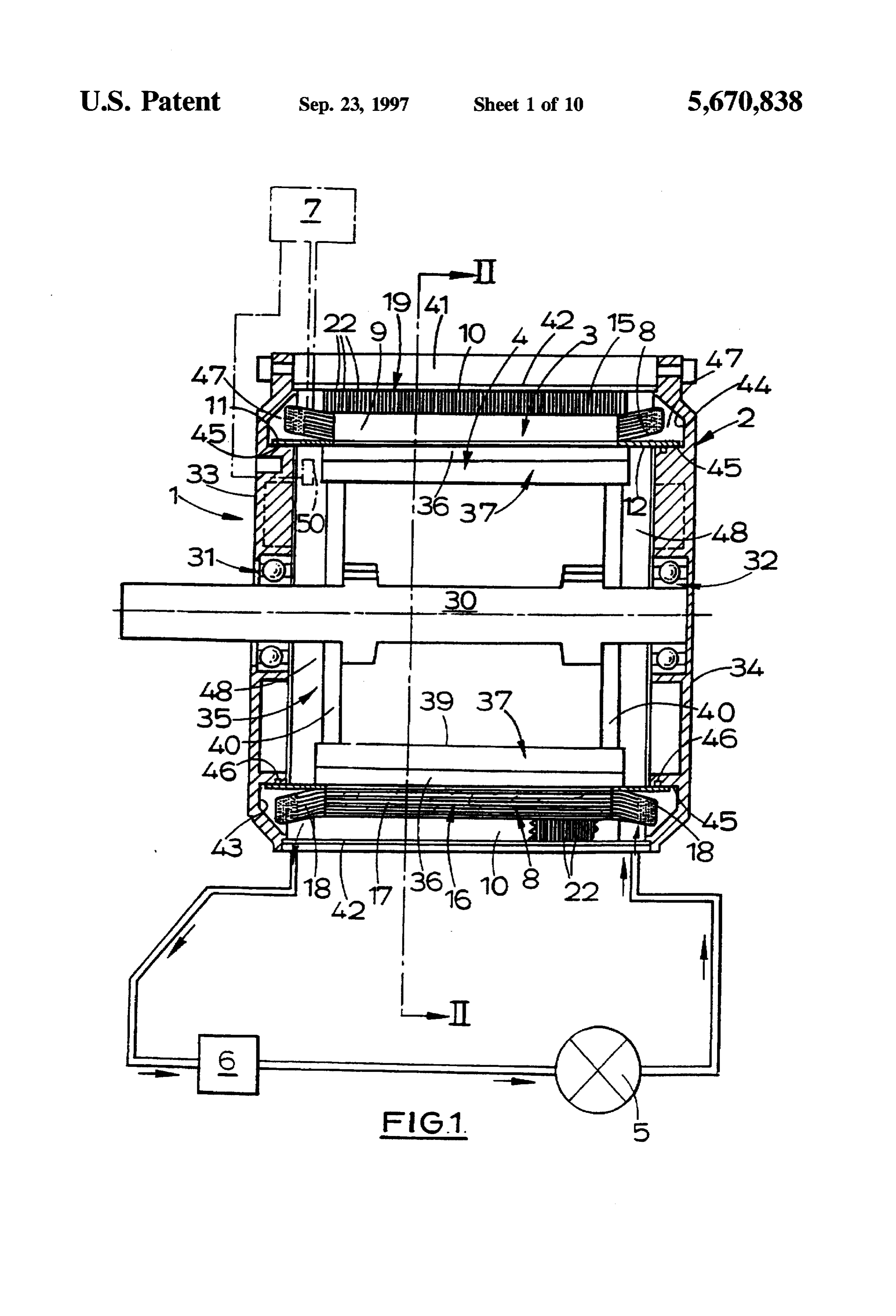
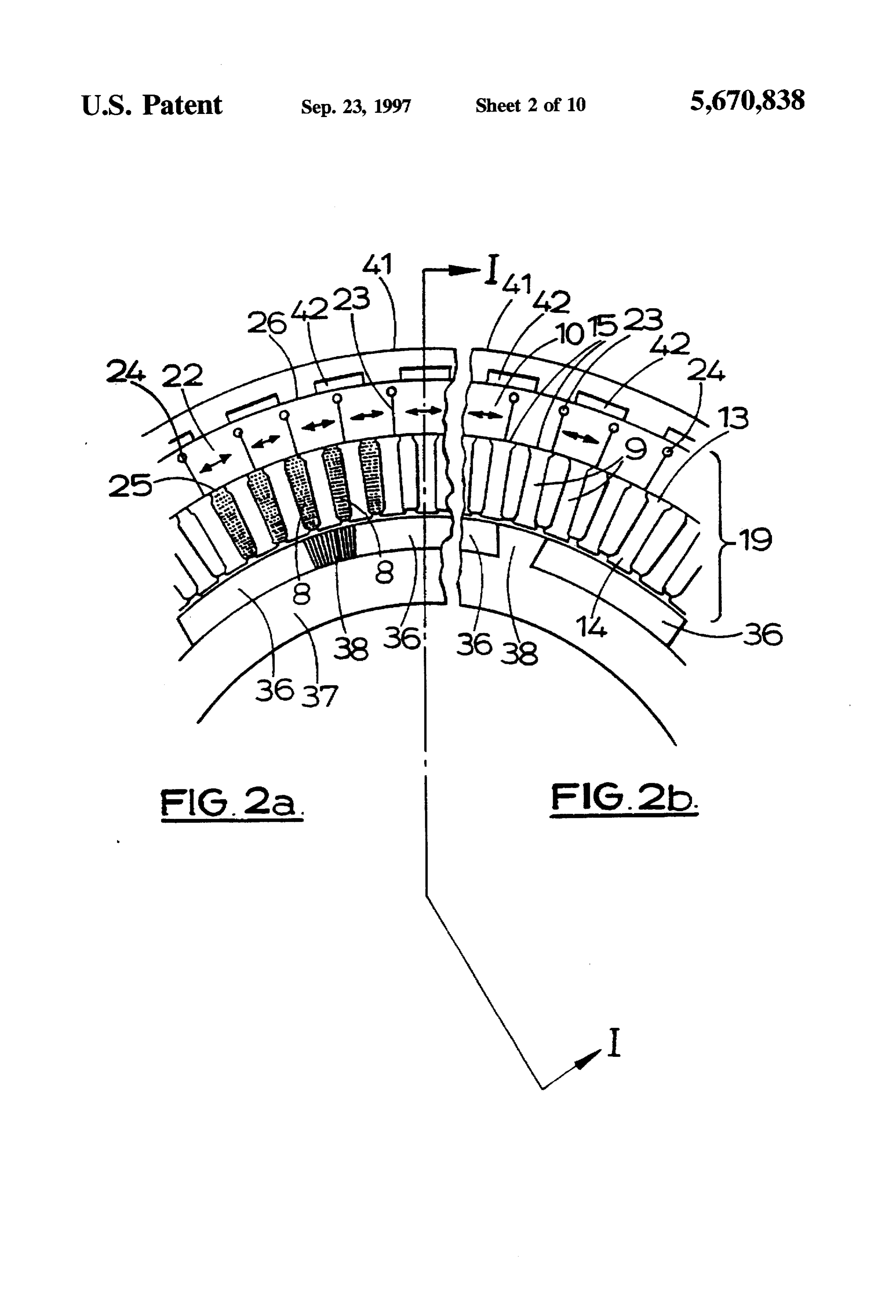
erally parallel to each other, at least in a central region of the FIG. 1 shows a cross-section of a brushless D.C. motor tooth. The laminations at the central region preferably in accordance with the first, second, third and fourth aspects extend in generally radial planes. 20 of the invention;
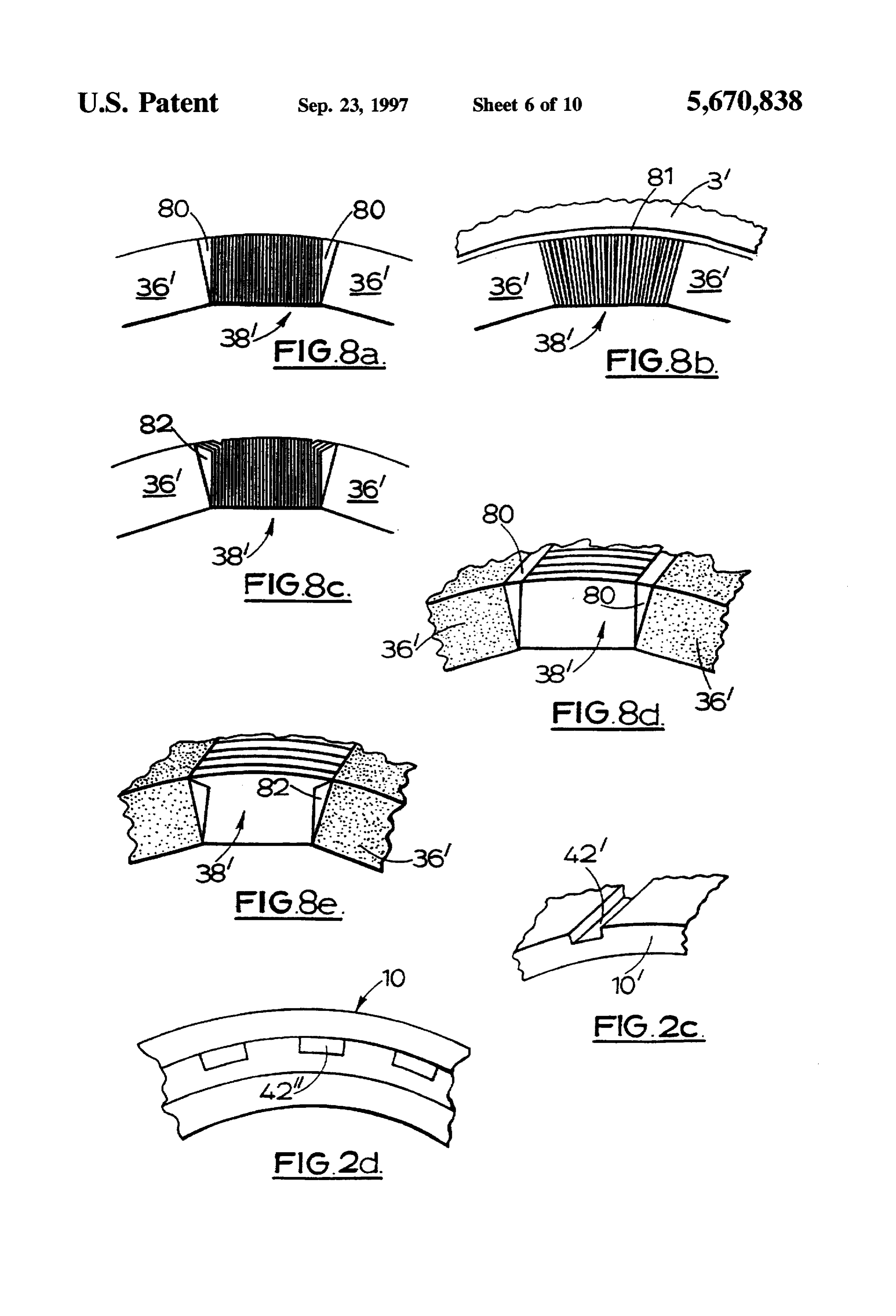
The laminations may diverge circumferentially at the FIG. 2a shows a cross-section on line I-II of FIG. 1; radially inner and/or outer ends of the tooth. FIG.2b shows a similar view to that of FIG. 2a, but of The teeth may have self-centering formations provided at a modified motor;
at least one, or either, circumferential side. The self FIGS. 2c and 2d show details of modified stator disc centering formation may be formed from a continuation of 25 assemblies;
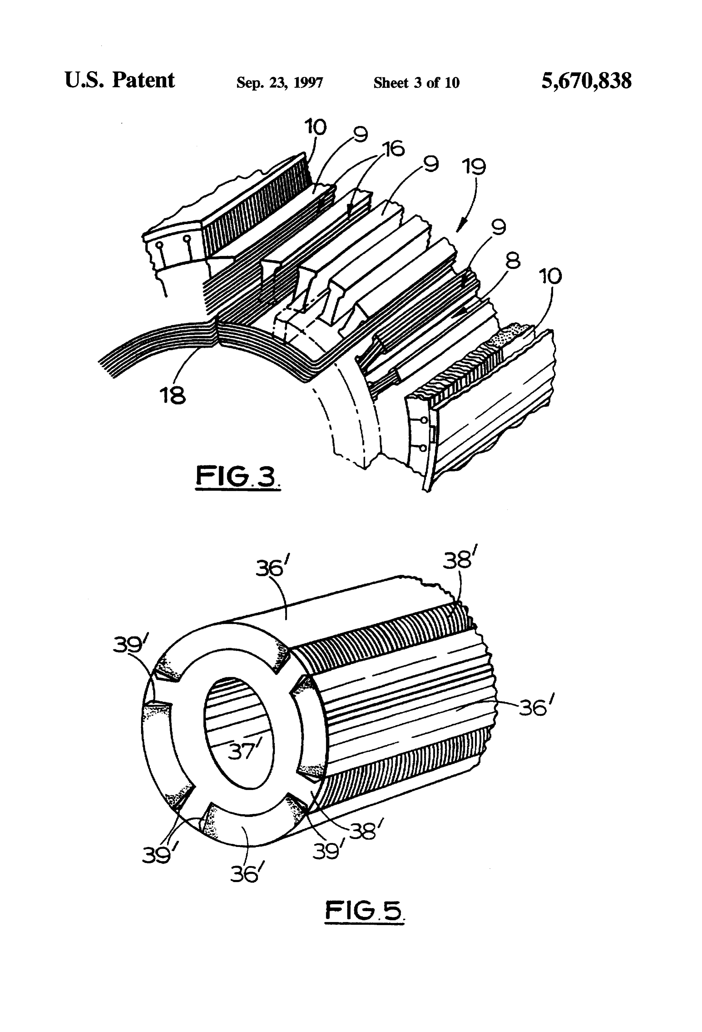
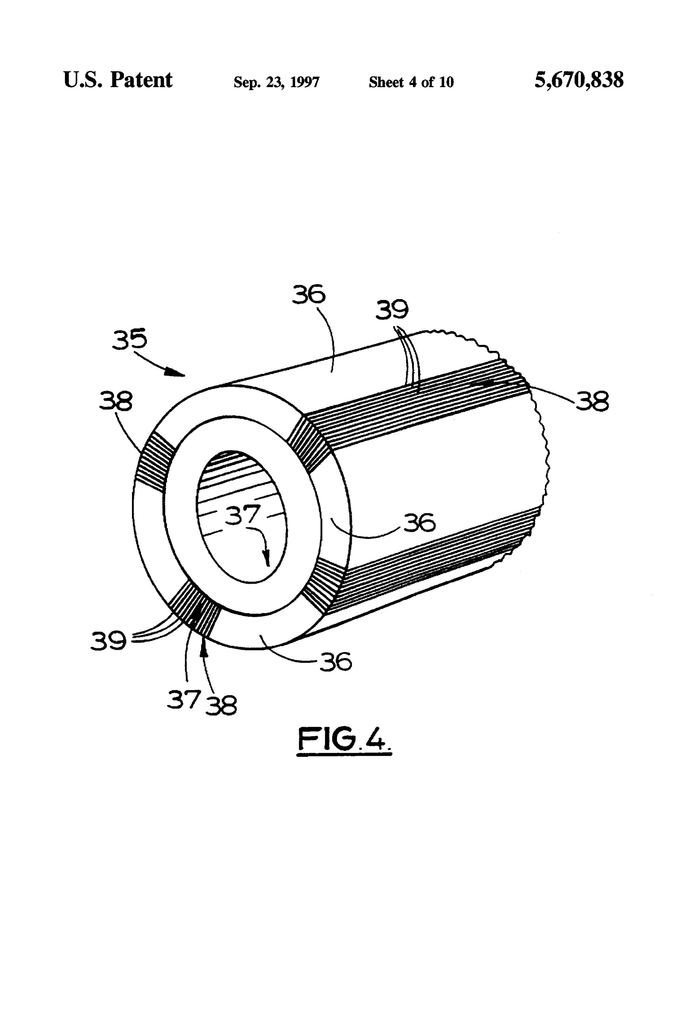
a lamination of the tooth, preferably the outer lamination of FIG. 3 shows features of detail of the stator assembly of a tooth. the motor of FIG. 1;
According to a third aspect the invention comprises a FIG. 4 shows features of detail of the rotor of the motor method of making a laminated tooth for an armature com of FIG. 1;
prising folding a continuous strip of sheet material back on F.G. 5 shows another rotor;
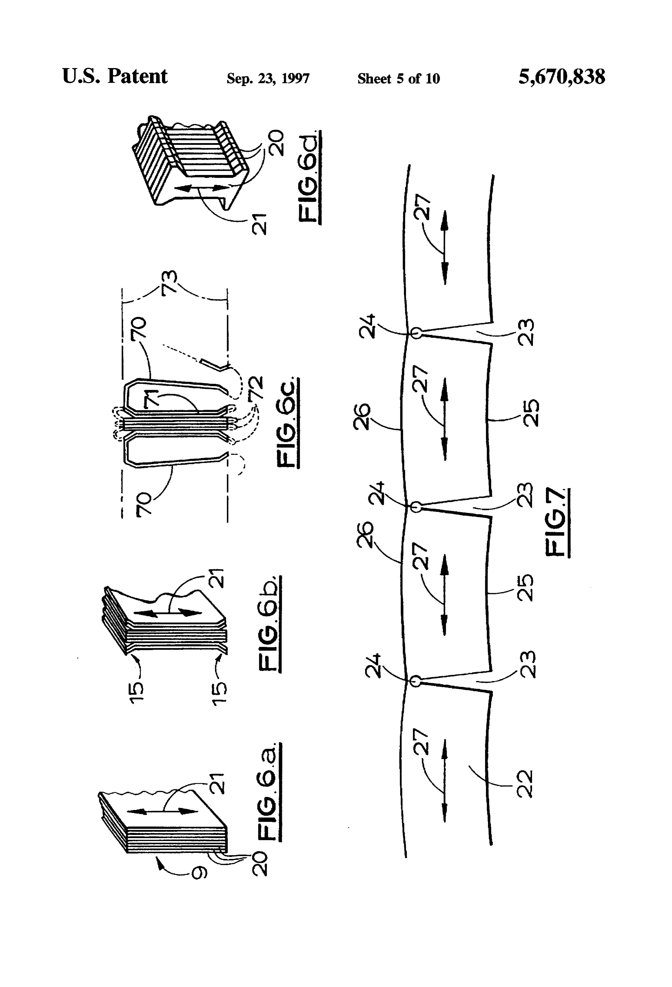
itself to form two adjacent laminations joined by a bend or FIGS. 6a to 6d show schematically sections through four corner region, and then removing the material of the corner alternative forms of teeth for the stator armature of the motor region. of FIG. 1;
This facilitates automisation of the manufacture of teeth. FIG.7 shows schematically a portion of a unidirectional The corner region may be ground off, preferably after the 35 steel strip used to make the flux return member of the stator laminations have been fixed together, for example by gluing. assembly of FIG. 3;
According to a fourth aspect of the invention a tubular FIGS. 8a to 8e show five alternative interpolar regions back, or return path, member of an armature is made by for the rotor of FIG. 4;
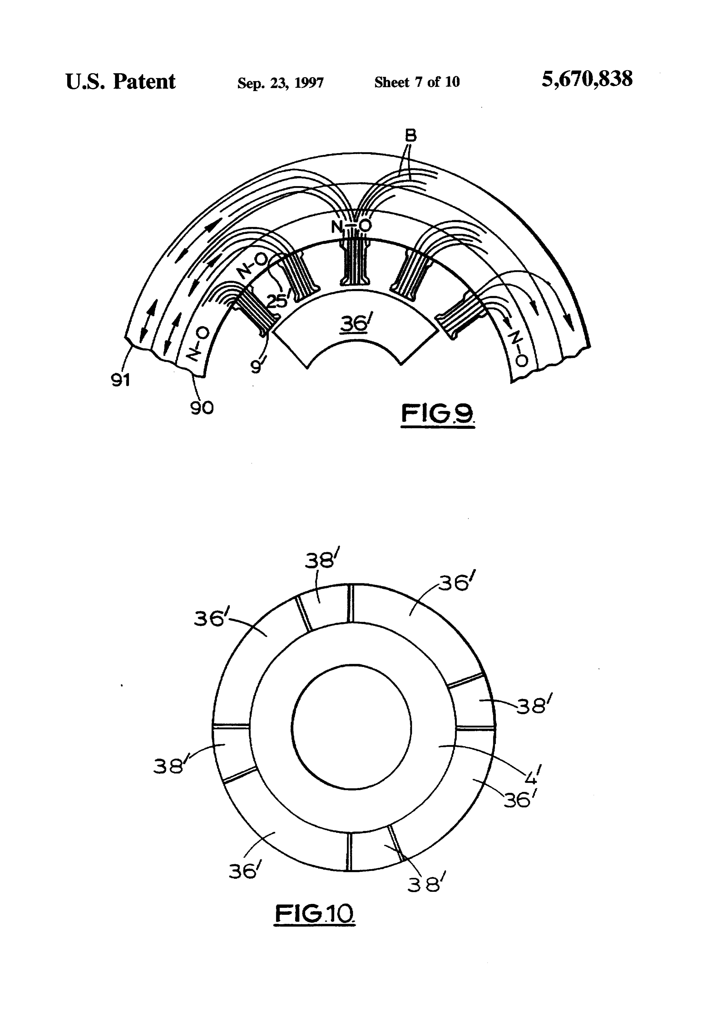
taking a continuous strip of magnetic material having a low FIG. 9 schematically shows a composite back plate and loss direction, and bending that strip around in an annular, teeth; FIG. 10 shows schematically a cross-section through helical, manner so as to form a laminated tube. a transducer rotor assembly;
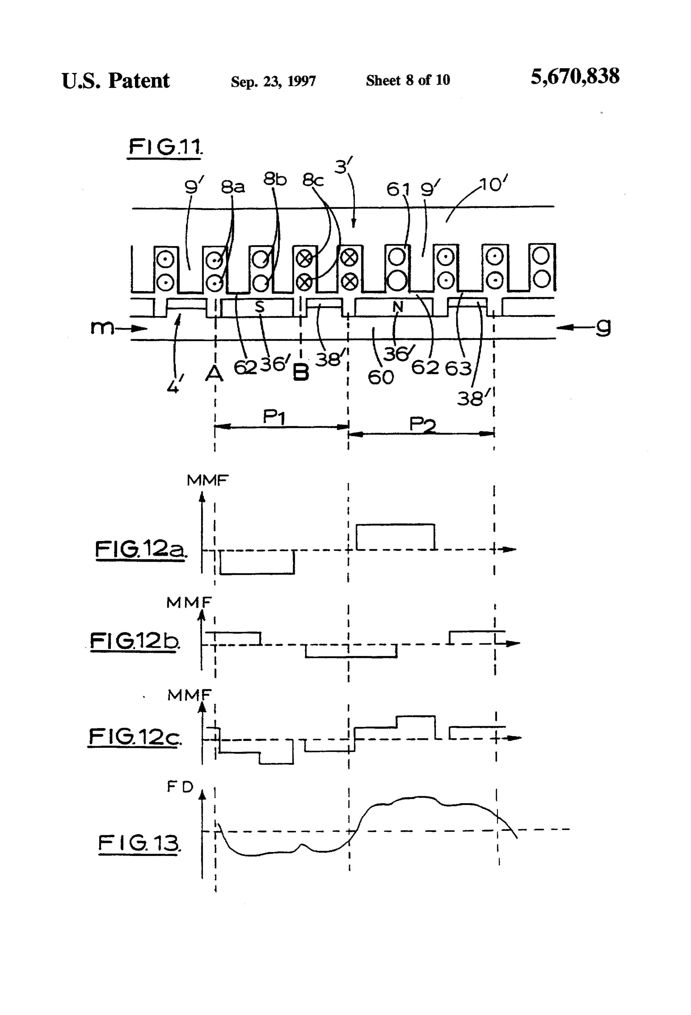
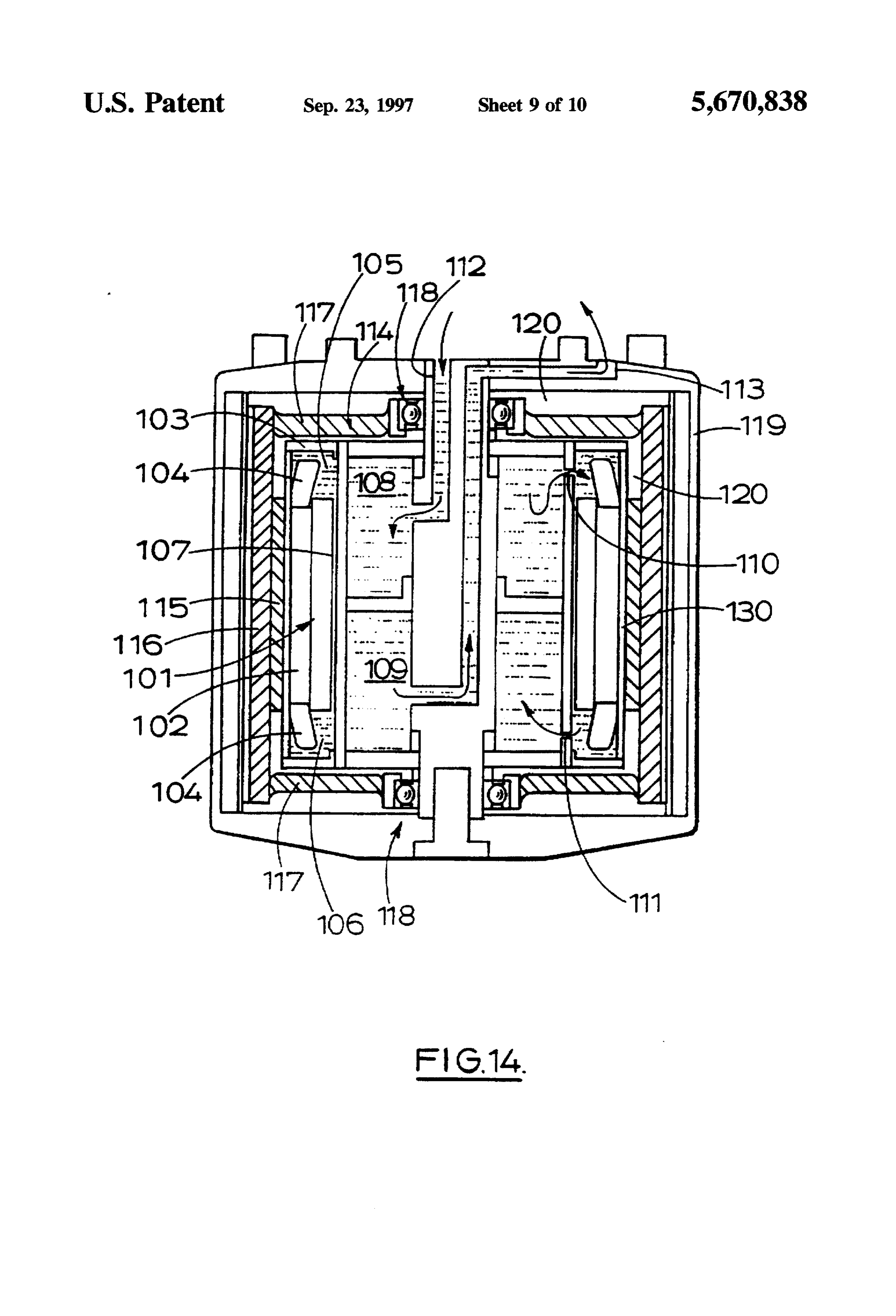
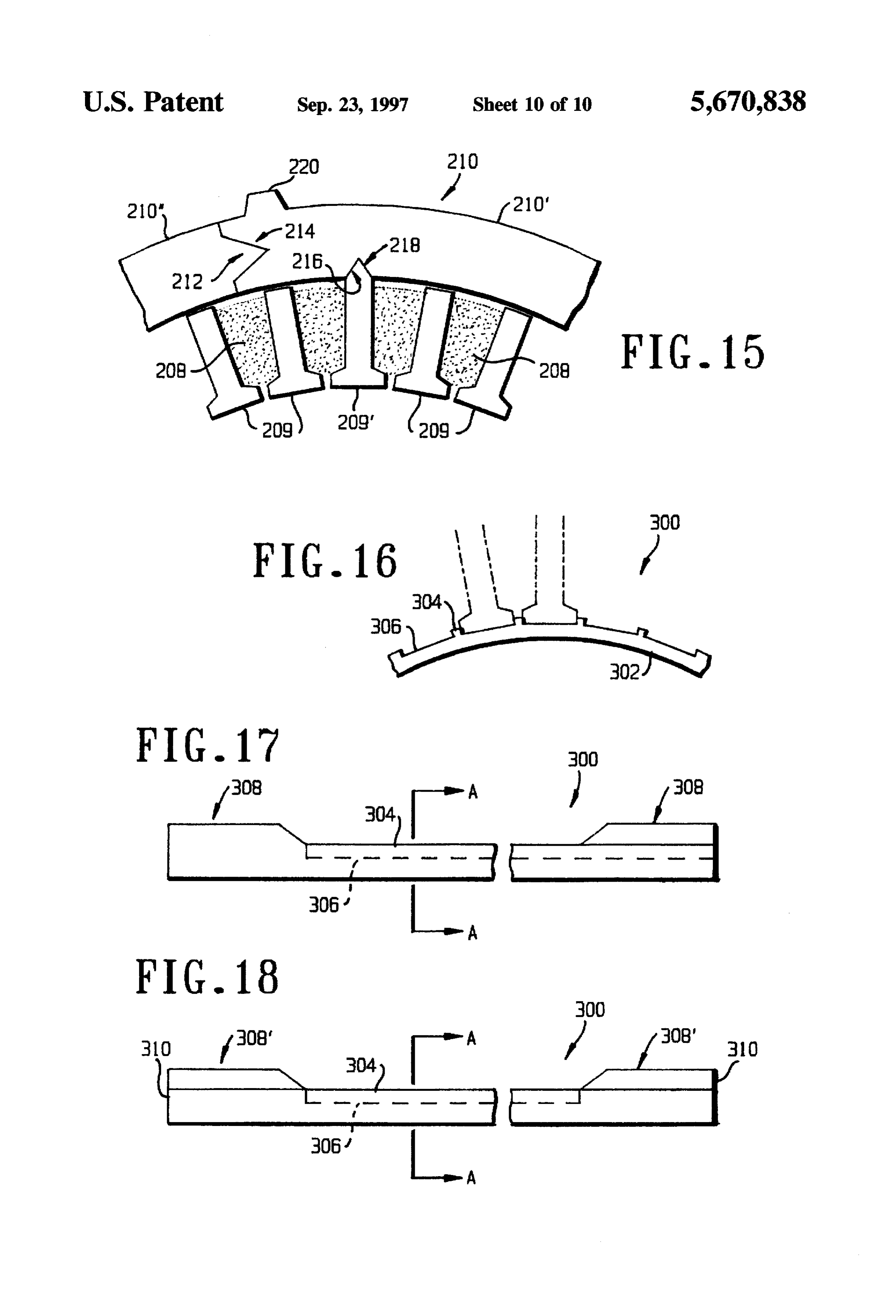
The strip is preferably slotted or notched prior to bend FIG. 11 shows schematically a linear transducer in order 1ng. to assist in illustrating the operation of the motor of FIG. 1; Preferably two adjacent layers of strip in the laminated FIGS. 12a to 12c show schematically the magnetomotive tube do not have superimposed notches or slots. 45 force waveforms of elements of the transducer of FIG. 11; According to a fifth aspect the invention consists in an FIG. 13 shows schematically how the flux density varies electromechanical transducer having an amature in accor across the air gap of the transducer of FIG. 11; dance with the second aspect of the invention or a tooth or FIG. 14 shows yet another transducer; back member made in accordance with the third or fourth FIG. 15 shows an armature comprising a backmember of aspects of the invention. 50 an alternative construction and teeth; A further aspect of the invention also was inspired by a FIG. 16 is a partial transverse section of a sealing collar desire to reduce losses from an electromechanical trans for a further alternative embodiment of the invention; and ducer. FIG. 17 and 18 are, respectively, longitudinal sections of According to a sixth aspect of the invention I provide a first and second alternative forms of the sealing collar of rotor member of an electromechanical transducer having a 55 F.G. 6.
plurality of angularly spaced magnets and interpolar ele FIGS. 1 to 4 show a brushless D.C. motor 1 of about 60 ments interposed between adjacent magnets, the interpolar horse power comprising an outer housing or casing 2, a elements having anisotropic magnetic properties such that stator assembly 3, and a rotor assembly 4. A pump 5 and a they have a low magnetic reluctance direction extending in heat exchanger 6 are provided as described later. An elec a generally radial direction and relatively high magnetic tronic controller 7 controls the supply of electricity to the reluctance in a circumferential direction. moto.
Thus there is not just air between adjacent magnets. This The stator assembly 3 comprises an armature having enables us to minimise eddy currents in the interpolar windings 8 of copper wire, a series of angularly spaced and regions of the member, provide greater control of the flux axially elongate teeth 9 interposed between adjacent wind between two poles of magnets, and may also enable us to 65 ings 8, a back or return path, member 10 forming a hollow control or limit the cross slot flux at the tips of an armature's cylinder around windings and teeth, and a pair of axially teeth. spaced sealing rings 11 and 12. The teeth 9 have in radial
Page 14
cross-section a flared or divergent head portion 13 adjacent The housing 2 comprises the two end plates 33 and 34 the back member 10 and a similarly divergent foot portion which are bolted to an axially extending cylindrical wall 41. 14 adjacent the rotor assembly 4 (see FIG. 2). The head Axially extending communication channels 42 are formed in portions 13 of the teeth are very slightly spaced from the the inner surface of the wall 41 and extend for its full axial back member 10 so as to create a magnetic back gap 15 length. The end walls 33 and 34 have annular chamber between them. This back gap 15 increases the reluctance spaces 43 and 44 formed into their inner surfaces, and an path for magnetic flux passing from the teeth to the back adjacent annular sealing face 45. The face 45 also defines a member which has the effect of reducing the self-inductance groove for an annular seal 46.
of the armature windings 3. The back gap is filled with resin The sealing collars 11 and 12 of the unitary stator to bond the teeth 9 to the back member 10 and the resin O serves as a magnetic reluctance. structure 19bear against the sealing faces 45 of the end walls The windings 8 have central portions 16 embedded in 33 and 34, trapping the annular seals 46 so as to form a seal isolating axially spaced annular end turn chambers 47 from resin 17 and end portions 18 extending beyond the resin 17. an inner, central, chamber 48. The end turn chambers 47 are The end portions 18 comprise the end turns of the windings, which end turns are not covered by the thermally insulating 15 defined in part by the chamber spaces 43 and 44, in part by resin 17 such as araldite epoxt resin or an inorganic resin. the sealing collars 11 and 12, in part by the end turn portions The resin 17 also embeds the teeth 9 and forms the teeth and 18 of the windings, and in part by the back member 10. The windings into a unitary stator structure 19. The sealing two end turn chambers 47 communicate with each other via collars 11 and 12 can be independent elements or combined the channels 42. (In an alternative structure the two sealing into a single structure (for example they may be ends of collars 11 and 12 are opposite ends of a continuous cylinder continuous cylinder, which may be of plastics material) and of plastics isolating member which forms a seal with each are made of non-magnetic, non conducting material, and are end plate 33 and keeps the cooling liquid from the rotor attached at one of their cylindrical ends to the unitary stator assembly. The cylinder is disposed between the windings 8 structure 19. The other end of the sealing collars 11 and 12 and the chamber 48).
are adapted for sealing engagement with the housing 2, as The end turn chambers 47 hold cooling liquid which is in will be described later. The sealing collars, or rings 11 and 25 direct contact with the end turns of the windings (which are 12 may be made of glass filled plastics material, or non not embedded in the resin). The pump 5 circulates the magnetic stainless steel. cooling liquid, which may be oil, through the heat exchanger Each tooth 9 is made from laminations 20 of unidirec 6 to dissipate heat generated by the operation of the motor. tional steel (steel having a single low loss direction). The Although only the end turns of the windings are directly laminations 20 are best seen in FIGS. 3 and 6 and extend 30 cooled I have found that this is quite sufficient and allows us axially and radially and lie in a substantially radial plane of to have a unitary stator using conventional resin embedding the armature. The low loss direction of each lamination is techniques.
represented by arrow 21 of FIG. 6a and extends in a radial The provision of a separate heat exchanger 6 may not direction. always be necessary: circulating the cooling liquid within The back member 10 is made from a continuous strip 22 35 the housing may cool the motor sufficiently. of unidirectional steel (shown in FIG. 7) wound in a helix so The central chamber 48 may be evacuated and hermeti that adjacent turns of the helical form adjacent laminar cally sealed during the manufacture of the motor. This layers. The strip 22 is punched out of a band of unidirec reduces frictional resistance to the rotation of the rotor tional steel and has wedge-shaped slots 23 centred on holes assembly. Although I prefer to provide a hermetically sealed 24, and arcuate inner and outer edges 25 and 26 to enable it chamber 48, in an alternative motor means could be pro to be wound to form the back member 10. The low loss vided to evacuate the chamber 48 either continuously or direction of the strip 22 is represented by arrows 27. periodically. I also envisage that in certain circumstances it When the strip 22 is wound to form the back member 10 might be preferred to fill the chamber 48 with a chemically it comprises many segments each having allow loss direction inert gas, such as nitrogen. This would reduce corrosion of pointing generally tangentially to the pitch-circle of the back 45 the magnets.
member 10, adjacent segments having low loss directions The supply of a trapezoidal waveform electric current to pointing in slightly different directions. This gives the over the windings 8 is controlled by the controller 7 in response all back member 10 a generally circumferential low loss to the angular position of the rotor assembly 4 (which is direction. The holes 24 and slots 23 of any two adjacent sensed by a position sensor schematically indicated as layers of the wound strip 22 are not superimposed. In less reference number 50), and in response to the performance preferred versions superimposition may be allowed. required from the motor. Position control of the switching of The rotor assembly 4 comprises a main shaft 30 jour the current to the armature can control the effective magnetic malled for rotation by bearings 31 and 32 mounted in end flux per pole, and hence the back emf, over a wide range. walls 33 and 34 of the housing 2, and a rotor body 35. The The controller 7 advances and retards the switching position rotor body 35 comprises twelve permanent magnets 36 (for 55 in order to obtain field weakening and field strengthening example neodymium-iron-boron magnets) equiangularly effects as required.
spaced and recessed in a solid or laminated carrying body The operation of the motor 1 will be described with 37. FIG. 4 only shows four magnets 36 for simplicity. reference to the simplified four pole arrangement of FIGS. Interpolar regions, or interpoles 38, extend between the 10 to 13.
magnets 36. The interpoles 38 comprise axially extending Permanent magnets 36 are separated by laminar inter radial laminations 39 (see FIG. 4) and serve to reduce pole poles 38. FIG. 11 shows the arrangement in linear fashion face losses in the motor. The carrying body 37 is connected for simplicity and further illustrates a return path member 60 to the main shaft by end plates 40 of the rotor body 35. for the rotor 4. The stator 3' consists of polyphase windings The interpoles 38 have a relatively high magnetic reluc 8a, 8b, 8c placed within slots 61 formed between soft tance circumferentially. This is achieved by arranging for the 65 magnetic material or composite teeth 9 which in turn abut low reluctance direction of the laminations 39 to be gener or are formed as part of a flux return member 10. Air gaps ally radial. 62 and 63 are formed between the magnets 36' and the teeth
Page 15
9 and between the interpoles. 38' and the teeth 9. It is the current flow is necessary to obtain four quadrant opera advantageous in some instances to make air gap 63 between tion. Current control (chopping the current to limit its value) the interpoles and the teeth smaller than the air gap 62 can be used to determine the power output from the trans between the magnets and the teeth. This can help to provide ducer.
a better balance of the flux between the PM. and the steel Position control (i.e. control of the point at which switch poles. The directions of rotation of the rotor when the ing of each phase occurs) is an essential requirement of the transducer is used as a motor and when used as a generator proposed transducer operation. Power output can be deter are illustrated by arrows m and g. The pitch between mined at any rotor speed by incorporating an appropriate adjacent South and North poles when the motor is switching algorithm or look-up table in the control software of the at point A is represented by dimensions P1 and P2. O controller 7.
FIG. 12a shows diagrammatically the linear, and hence An advantage of the proposed transducer is that it phase, relationships of the Magneto-Motive Force (MMF) reduces the amount of permanent magnet material required. produced by the permanent magnetic fields in the linear For a given maximum power output, the magnet pole arc can transducer (motor) shown in FIG. 11. FIG. 12b shows the be reduced when compared to a conventional machine due MMF produced by the windings of the stator of the motor of 15 to the field strengthening effect of the winding current. Since FIG. 11. The combined MMF's form a composite waveform the thickness of pole required to prevent demagnetisation which is shown in FIG. 12c to produce an increased average under limiting temperature and current conditions is related magnetic flux emanating from each magnetic pole. FIG. 13 to the pole arc, the thickness of the pole may also be reduced shows a typical air gap flux density waveform. by a similar amount. The overall reduction in permanent The stator's MMF is shown at the top and the rotor's magnet material may greater than thirty percent when com below. The toothed stator is shown with a three phase pared to a conventional transducer construction. This makes winding employing one slot per phase. Each pole of the rotor the transducer far cheaper to manufacture. comprises a permanent magnetspanning approximately fifty The speed range of permanent magnet transducers is five percent of the pole pitch and the inter-pole spanning usually limited by the voltage available from the supply. approximately thirty percent of the pole pitch. The perma 25 Although series-parallel switching can extend the speed nent magnets are located symmetrically between the inter range, the cost and complexity of controls is unavoidably poles. The width of the resultant gaps is chosen to provide increased. The inclusion of interpoles will enable the oper an adequate flux break between the magnets and the inter ating flux density for part of the pole arc to be increased by poles such that it minimises flux leakage and prevents about fifty percent over that available from neodymium excessive cogging torque. 30 boron iron permanent magnets. The overall increase influx It will be appreciated that, owing to the symmetrical per pole is estimated to be about twenty percent. Compared arrangement of the poles, both directions of rotation are with a conventional transducer, the stall torque would there achievable, this being dependent upon the choice of position fore be increased by twenty percent. A or B as the reference for the switching of the armature Thus the motor of FIGS. 1 to 4 when operated as current. 35 exemplified by FIGS. 10 to 12 needs power semiconductors If the transducer is operated as a motor, position Ais used of a lower voltage and/or lower current rating than conven as the reference switching position for clockwise rotation, tional D.C. brushless motors, has less permanent magnet and if the transducer is operated as a generator, position B material, has an increased speed range, an increased starting is used as the reference switching position for clockwise torque, and less easily demagnetised permanent magnets. rotation. Modifications of some of the components of the motor 1 The transducer is therefore capable of four quadrant are shown in FGS. 2b-d, 5, 6, 8, 9, and 14. operation. FIG.2b shows a section through a motor similar to that Although FIG. 11 is shown in the simplest three phase of FIG. 1 (and the same reference numerals have been given) arrangement, it is preferred to choose a greater number of except that the interpoles 38 and the body 37 of the rotor of slots per pole per phase in order to reduce the cogging torque the motor are made from laminations which are in planes to a minimum. normal to the axis of rotation. The body 37 and interpoles 38 FIG. 12c shows the MMF waveforms when phase one are made from the same laminated sheet material. The has zero current and phases two and three are at peak structure of the rotor is similar to that shown in FIG. 5. current. The combination of the MMF waveforms partially FIG.2c shows the provision of communication channels, depends upon the phase relationship of the stator currents 50 referenced 42, in the back member 10', either instead of or with the rotor position, so that a lagging current will result in addition to the channels 42 of the arrangement of FIGS. in the stator winding MMF shifting to the right whilst a 1 and 2. If communication channels are provided in both the leading current will result in a shift to the left. back member and the outer wall 41 those of the wall may be By switching the armature currents in relation to the rotor superimposed with those of the back member so as to give position the stator MMF waveform can be shifted to either 55 channels of greater cross sectional area, or they could be weaken or boost the permanent magnet field. With a pure offset.
permanent magnet transducer this would have little effect on FIG. 2d shows the provision of communication channels the flux, but by including the inter-poles flux variations of 42" in an intermediate layer of the backing member (see greater than sixty percent are possible. FIG. 9). The channels 42" could extend completely through The maximum variation influx will occur with the stator the radial depth of the layer in which they are provided. current at its maximum. Lower currents give proportionally FIG. 5 illustrates an alternative way of recessing the reduced range of control. However, when no current is magnets 36 in the rotor assembly to that shown in FIG.2a. applied to affect the permanent magnet field the proposed The carrying body 37 is made from laminated steel, with the transducer will have less flux than a conventional transducer laminations being in diametral planes. The interpoles 38 so and will thus reduce the back emf. 65 produced are not as efficient as those of FIG. 4 at reducing Power semiconductors can be arranged in the normal magnet to magnet flux since they have less resistance to three phase full-wave bridge circuit, but means of reversing circumferential flow of magnetic flux. Air gaps 39' are
Page 16
provided between the interpoles 38 and the magnets 36. I also envisage an inverted arrangement of the motor of These introduce a high reluctance into the path between FIG. 1 where the stator is on the inside and the rotor on the magnetic poles and cause the magnetic flux to be directed outside. This is shown in F.G. 14. FIG. 14 also shows the more radially to the teeth of the stator where it can serve a arrangement of isolating the cooling liquid from the rotor useful purpose, avoiding magnetic short circuits. using an integral sleeve member 130 extending for the axial The arrangements of FIG. 5 could be modified by the length of the machine, rather than two separate sealing provision of interpoles as separate elements carried by a collars 11 and 12 (this possibility is discussed in relation to cylindrical body 37. an "inner rotor” machine at page 13, third paragraph). The teeth 9 of the motor could be as shown in FIG. 6a, In the inverted arrangement shown in FIG. 14 a solid being basically rectangular in cross section and having no 10 armature 101 comprising windings 102 embedded in resin is head or footportion; or as shown in FIG. 6b having head and affixed to cylindrical end pieces 103 to form a stator assem foot portions 15; or as shown in FIG. 6d in which the bly. End turns 104 of the windings 102 occupy enclosed laminations 20 are in planes normal to the axis of rotation; annular end turn chambers 105 and 106 which are connected or as shown in FIG. 6c, having self-centering spring forma by passageways 107. Inlet and outlet circulation chambers tions 70. Such a tooth need not be very accurately positioned 15 108 and 109 are defined in the central region of the stator and during manufacture since its formations 70 will tend to communicate with the annular end turn chambers 105 and centre it in whatever space it occupies. 106 via ports 110 and 111 respectively. An inlet 112 supplies The teeth may be formed by an automated process in coolant to the chamber 108 and coolant leaves chamber 109 which a continuous strip of metal is repeatedly folded upon via an outlet 113.
itself so as to have generally parallel central regions 71 and A rotor 114 comprises magnets 115 affixed to a return fold regions 72 at the ends of the central regions 71. The fold path member 116 which is journalled for rotation on the regions 72 are then ground off or otherwise removed to leave stator assembly via diaphragm plates 117 which are con just the desired central regions. Lines 73 of FIG. 6c indicate nected to bearings 118.
grinding planes. This method of making a tooth may com An outer containment housing 119 surrounds the rotor prise yet another invention, and is of course applicable to the 25 114 and defines a sealed rotor chamber 120 in which the manufacture of interpoles as well as teeth. rotor 114 rotates. The housing 119 is connected to the stator FIGS. 8a to 8e illustrate a number of different interpoles assembly in a sealed manner such that the rotor chamber 120 38. The interpole of FIG. 8a comprises a rectangular block can be permanently evacuated during manufacture of the of laminations and introduces an air gap 80 between the machine.
outer laminations and the magnets 38. FIG. 8b has evenly 30 The rotor 114 has a significant mass and can be used as distributed laminations arranged as a fan. This presents a a flywheel to store energy when the transducer is in opera uniform flux capability to the air gap 81 between the rotor tion (for example in a vehicle). A suitable electronic con assembly and the stator assembly. FIG. 8c shows an inter troller may even allow us to reclaim some of the energy pole having bent laminations at its circumferentially spaced stored in the rotor, by example by using the motor as a sides which provide a partial air gap 82 whilst still present 35 generator. Alternatively or additionally it could be reclaimed ing a more uniform flux to the air gap between the rotor and mechanically, possibly using a kind of clutch arrangement. stator assemblies. The interpoles of FIGS. 8d and 8e are The motor of FIG. 1 has been designed for use in a similar to those of FIGS. 8a and 8c, having air gaps 80 and vehicle, such as an automobile. I propose to provide a motor 82, but their laminations lie in planes normal to the axis of at one or more, preferably all, of the road-engaging wheels rotation of the rotor. of the vehicle. The motor of FIG. 1 gives us a form of I have been surprised to find that the interpole arrange continuously variable transmission for the vehicle. The ments discussed produce a significant reduction in cogging vehicle is preferably an internal combustion engine torque. I believe that this is due to magnetic flux at the outer electric drive hybrid in which an I.C. engine powers a radial, and outer circumferential, edge of a magnetic pole battery which in turn powers the motor.
being "short-circuited" through the first lamination of the 45 I have found that when a motor similar to that of FIG. 1 adjacent interpole and thereby not being available to pro is to be used in circumstances where superconductor duce cogging torque. Thus a method of reducing cogging windings, or strips taking the place of windings, are torque could be to provide appropriate interpoles. This employed it can be desirable to have the winding in intimate reduced cogging torque effect may not require more than a contact with a cooling conduit. For example the winding single lamination of an interpole with an appropriate mag 50 wire could be provided inside a cooling conduit. The cooling netic barrier between them (for example a layer of resin). conduit, incorporating a winding wire or strip, could be FIG. 9 schematically illustrates a composite back mem formed onto the stator as a winding, or in a similar manner ber 10' for the stator assembly. Teeth 9 are provided to that of a winding.
adjacent, but just spaced from, an inner layer 90 so as to A portion of an armature incorporating an alternative provide the air gap 25. One or more outer layers 91 are also 55 back, or return path member 210 is illustrated in FIG. 15, provided. The inner layer 90 is made of amorphous, or together with a plurality of teeth 209, 209. The machine of non-orientated, steel which has a high flux capacity in any which the armature forms a part may, for example, be a direction, whilst the outer layer or layers 91 is made of transducer similar to that described with reference to FIG. 1. unidirectional steel with its low loss direction bent around so The back member 210 is an assembly of a plurality of as to extend generally tangentially. Thus where the flux from arcuate, segmental components 210.210" of unidirectional the teeth turns to flow circumferentially to another tooth it steel, the low-loss direction being transverse to the axis of does so predominantly in the amorphous steel, yet where it curvature of the segment, around the back member 210. extends generally in a "straight" line or circumferential arc Alternatively the back member segments may be isotropic. it does so largely in unidirectional steel along the low loss End faces of adjacent segments 210'. 210" are in close direction. The arrangement of FIG. 9 could be modified by 65 contact with one another in the assembled back member 210. providing axial fluid communication channels in one or Contacting end faces are provided with interengaging more of the outer layers 91. as suggested by FIG. 2d. formations. in this embodiment, a complementary projection
Page 17
212 and groove 214, to locate adjacent segments 210", 210" member 10, described with reference to FIG. 1. The hous with respect to one another. As described with reference to ing of a transducer (not shown in FIG. 15 but shown as 41 FIGS. 1 and 2, the armature further comprises teeth 209, in FIG. 1) has, in such embodiments, a corresponding 209" extending radially inwardly of and attached to the back longitudinal groove into which the rib 220 is received in member 210. Windings 208 are disposed between adjacent 5 order to provide an alignment datum between the armature teeth 209, 209'. Most of the teeth 209 have radially outer end and the housing and to transmit torque therebetween. surfaces of arcuate form to correspond to the inner surface The principle of contructing a stator of a motor of the segments 210'.210" to which they are secured. In this (transducer) from the inside outwards, assembling the back embodiment, a small number of teeth 209" (perhaps, only member from the inside around the windings, may itself be two to four in a transducer) have an end formation which 10 inventive, whether or not the back member is made of engages with a complementary formation of the segment segments.
210' to which it is attached. Typically, such teeth 209" have I claim:
a pointed end 216 which is located within a longitudinal 1. An electromechanical transducer for an electrically groove 218 in the inner surface of the segment 210, powered automobile, said transducer comprising:
although it will be understood that many shapes of comple 15 a housing;
mentary formations will be suitable. a stator, disposed within said housing, comprising a The provision of the small number of teeth 209 winding, said winding having a first region embedded described in the last-preceding paragraph has the advantages in thermal insulating resin, and a second region not of (a) providing a mechanical connection between the teeth embedded in said resin;
209, 209" and the associated windings 208, and the back a rotor, disposed within said housing, comprising (i) a member 210 through which torque generated by the wind main shaft, and (ii) at least one permanent magnet ings 208 may be transmitted; and (b) providing a reference disposed in operative association with said stator; datum by means of which angular alignment between the teeth 209, 209' and windings 208, and the back member 210 means, operatively disposed within said stator, for fluidly may be achieved. Angular alignment of the teeth relative to, 25 isolating said second region of said winding from a for example, position sensors may be important in the remaining portion of said transducers; and electronic control of the motor. means, influid communication with said second region of An armature may be formed incorporating a sealing said winding, for circulating coolant over said second collar 300, as illustrated in FIGS. 16 to 18, which performs region of said winding, to thereby dissipate heat from the function of the collars 11, 12 described with reference to said transducer; wherein:
FIG. 1, and, further, simplifies assembly of the armature. said second region comprises a plurality of end turns of The sealing collar 300 is a generally cylindrical con said winding;
struction having a thin central portion and thickened outer said first region comprises a central portion of said endportions 308,308". The collar 300 provides a continuous winding that is between said plurality of end turns; impermeable membrane through the machine. The thin 35 and central portion has radially-outwardly projecting, axial said coolant is in direct cooling contact with said ridges 304, between which are defined axial grooves 306, second region, but not with said first region. there being the same number of grooves 306 as armature 2. An electromechanical transducer comprising: teeth 209, 209. The thickened end portions 308,308 serve a rotor member;
to provide structural reinforcement for the collar 300 and a stator member;
also provide a sealing body, as will be described. Alternative an electrical winding on a first one of (i) the rotor member arrangements of the end portions 308, 308' are shown in and (ii) the stator member; FIGS. 17 and 18. In FIG. 17, one end portion 308 is isolating means for isolating at least a part of said first one integrally formed with the collar to provide reinforcement of (i) the rotor member and (ii) the stator member from while in FIG. 18, a stiffening ring 310 is applied to the collar 45 a second one of (i) the rotor member and (ii) the stator 300 at its end portions 308. The stiffening ring may be member; and forced into the winding/tooth assembly after the windings and/or teeth have been attached, cooling fluid in direct contact with said part, said isolating Construction of an armature incorporating the collar 300 means isolating said part from the second one of (i) the may be carried out as follows. The collar 300 is formed first, rotor member and (ii) the stator member; as described above. Then, the teeth 9, 209, 209" are secured a plurality of end turns of said electrical winding being to the collar 300, inner end surfaces of each tooth being disposed on said part; and attached to the collar 300 within a respective groove 306. said cooling fluid being in direct contact with said plu The grooves locate the teeth relative to each other in the rality of end turns, but not with a central portion of the correct positions. This forms an assembly of the collar 300 55 electrical winding between the plurality of end turns. and teeth 9, 209, 209 substantially in their mutual arrange 3. A transducer according to claim 2, further comprising ment in which they will be incorporated into the armature. a cooling circuit fluidly associated with said first member, Onto this assembly, the armature windings 8,208 are wound means for forcing said fluid around said circuit. and subsequently the back member 10, 210 is applied (the 4. A transducer according to claim 2 in which the rotor last step being most easily carried out in the case of the member is isolated from the cooling fluid. segmental back member as described with reference to FIG. 5. A transducer according to claim 2 in which the central 15). The thickened end potions 308,308' of the collar then portion and the plurality of end turns are held in a thermally perform the function of the sealing collars 11, 12 described substantially uninsulated manner.
with reference to FIG. 1. 6. A transducer according to claim 2, in which the With reference to FIG. 15, an armature backmember 210 65 electronic winding comprises a plurality of windings inter may be provided with a longitudinal outwardly-projecting leaved with a plurality of magnetic field concentrating rib 220. The rib may equally be applied to a one-piece back CaS.
Page 18
7. A transducer according to claim 6 in which the trans 17. A transducer according to claim 15 in which the ducer has a central axis and a pair of axially spaced end chamber contains an inert, corrosion reducing gas. chambers into which the plurality of end turns project. 18. A transducer according to claim 2, wherein said 8. A transducer according to claim 7 in which passage transducer is a motor or a generator. means communicates one end chamber with the other so as 19. A transducer according to claim 18, further compris to allow said cooling fluid to flow between them. ing a cooling circuit, fluidly associated with said member, 9. A transducer according to claim 8 in which the passage and pump means for pumping said fluid around said circuit. means are provided in an outer housing. 20. An electromechanical transducer for an electrically 10. A transducer according to claim 8 in which the powered automobile, said transducer comprising: passage means are provided in a back, or return, path 10 a housing;
member disposed adjacent the windings. a stator, disposed within said housing, comprising a 11. A transducer according to claim 2 in which a fluid winding, said winding having a first central region passageway means is disposed adjacent to the windings so which is embedded in thermal insulating resin, and a as to cool a substantial length of winding. second region comprising a plurality of end turns of 12. A transducer according to claim 11 in which said 15 said windings which are not embedded in said resin; winding is effectively provided in an associated cooling fluid a rotor, disposed within said housing, comprising (i) a passageway, or at least forms part of the surfaces defining main shaft, and (ii) at least one permanent magnet the fluid passageway. disposed in operative association with said stator; 13. A transducer according to claim 2 in which a cooling sealing means, operatively disposed within said stator, fluid passageway conduit is wound onto the stator and 20 said sealing means and said resin acting to define a follows at least part, or substantially all, of the winding. chamber for fluidly isolating said second region of said 14. A transducer according to claim 2 in which said part winding from a remaining portion of said transducer; is isolated from the second member by a dividing wall. and 15. A transducer according to claim 2 in which the second means, influid communication with said second region of member is housed in a chamber which has an atmosphere 25 said winding, for circulating coolant over and in direct other than that of normal atmosphere air. cooling contact with said second region of said 16. A transducer according to claim 15, in which the winding, to thereby dissipate heat from said transducer. chamber is at least partially evacuated so as to have a low pressure. sk :k k . .
Provenance
- Collection
- Cited prior art
- Original PDF
- patentimages.storage.googleapis.com →
- Filed
- 1993-12-06
- Pages
- 18
- Method
- pdftotext (the PDF's own text layer) + pdftoppm 300dpi page scans
- Source
- Google Patents bibliographic record
- Granted
- 1997-09-23
- Inventors
- John M. Everton; Unique Mobility Inc
- Transcribed from
- patentimages.storage.googleapis.com →