patent · US2177801
Electric generator
31 October 1939
Page 1
Drawing sheet — no readable text.
Page 2
Patented Oct. 31, 1939 2,177,801
UNITED STATES PATENT OFFICE
ELECTRC GENERATOR,
Rudolf Arnold Erren, London, England
Application February 1, 1938, Serial No. 88,151
In Great Britain February 4, 1937
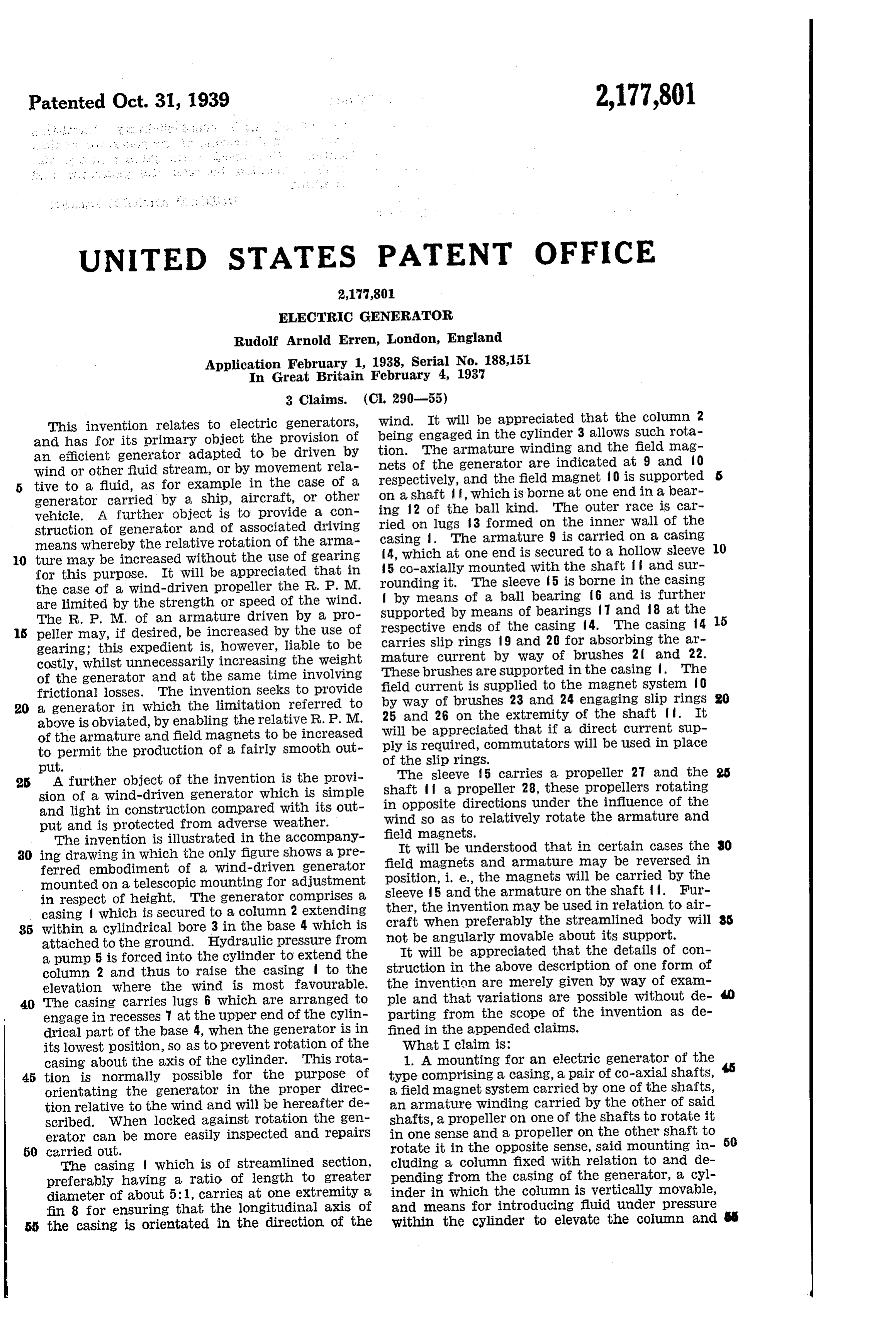
This invention relates to electric generators, Wind.
being
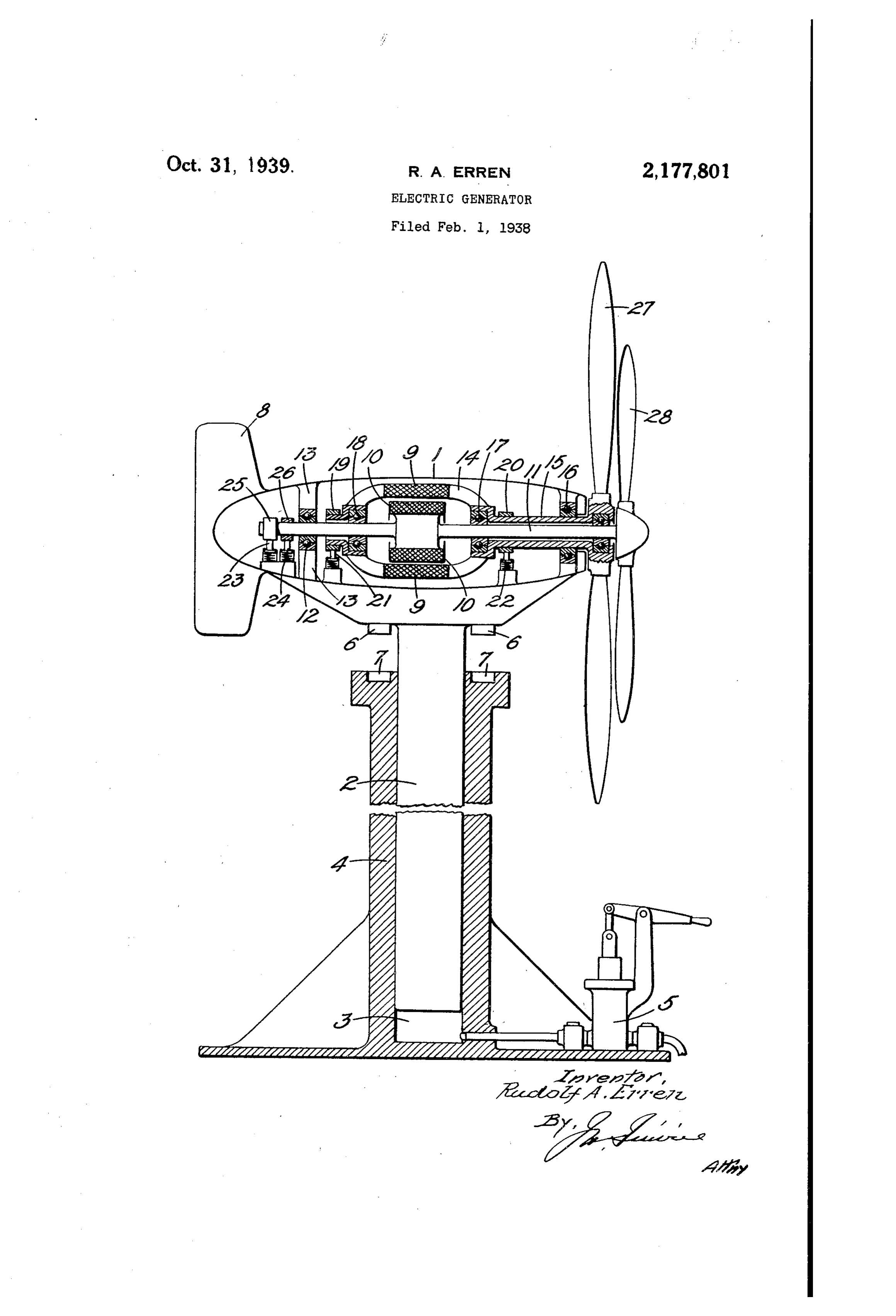
It will be appreciated that the column 2 engaged in the cylinder 3 allows Such rota and has for its primary object the provision of an efficient generator adapted to be driven by tion. The armature winding and the field mag Wind or other fluid stream, or by movement rela nets of the generator are indicated at 9 and O tive to a fluid, as for example in the case of a on a shaft and respectively, the field magnet 0 is supported generator carried by a ship, aircraft, or other ing 2 of the, which is borne at one end in a bear vehicle. A further object is to provide a con ried on lugs 3ball kind. The outer race is car formed on the inner wall of the struction of generator and of associated driving means whereby the relative rotation of the arma casing . The armature 9 is carried on a casing 4, which at one end is secured to a hollow sleeve 10 10 ture may be increased without the use of gearing 5 co-axially mounted with the shaft f f and sur for this purpose. It will be appreciated that in rounding it. The sleeve 5 is borne in the casing the case of a wind-driven propeller the R. P. M. by means of a ball bearing 6 and is further are limited by the strength or speed of the wind. Supported
The R. P. M. of an armature driven by a pro respective by means of bearings and 8 at the 15 ends of the casing 4. The casing f4 5 peller may, if desired, be increased by the use of gearing; this expedient is, however, liable to be carries slip rings 9 and 20 for absorbing the air mature current by way of brushes 2 and 22.
costly, whilst unnecessarily increasing the Weight These of the generator and at the same time involving brushes are supported in the casing . The frictional losses. The invention seeks to provide field current is supplied to the magnet system O 20 a generator in which the limitation referred to by Way of brushes 23 and 24 engaging slip rings above is obviated, by enabling the relative R. P. M. 25 and 26 on the extremity of the shaft . It of the armature and field magnets to be increased will be appreciated that if a direct current sup to permit the production of a fairly smooth out ply is required, commutators will be used in place put. Of the slip ringS.
25 A further object of the invention is the provi The sleeve 5 carries a propeller 27 and the sion of a Wind-driven generator which is simple shaft a propeller 28, these propellers rotating and light in construction compared With its out in opposite directions under the influence of the Wind so as to relatively rotate the armature and put and is protected from adverse weather.
The invention is illustrated in the accompany field magnets.
It will be understood that in certain cases the 30 30 ing drawing in which the only figure shows a pre field magnets and armature may be reversed in ferred embodiment of a wind-driven generator position, i. e., the magnets will be carried by the mounted on a telescopic mounting for adjustment in respect of height. The generator comprises a sleeve 5 and the armature on the shaft . Fur casing which is secured to a column 2 extending craft ther, the invention may be used in relation to air 35 Within a cylindrical bore 3 in the base 4 which is when preferably the streamlined body will attached to the ground. Hydraulic pressure from notItbewill angularly movable about its support. be appreciated that the details of con a pump 5 is forced into the cylinder to extend the column 2 and thus to raise the casing to the Struction in the above description of one form of elevation where the Wind is most favourable. the invention are merely given by Way of exam 40 The casing carries lugs 6 which are arranged to ple and that Variations are possible without de engage in recesses at the upper end of the cylin parting from the Scope of the invention as de drical part of the base 4, when the generator is in fined in the appended claims. its lowest position, So as to prevent rotation of the What I claim is:
casing about the axis of the cylinder. This rota 1. A mounting for an electric generator of the 45 tion is normally possible for the purpose of type comprising a casing, a pair of co-axial shafts, orientating the generator in the proper direc a field magnet system carried by one of the shafts, tion relative to the wind and Will be hereafter de an armature Winding carried by the other of said Scribed. When locked against rotation the gen shafts, a propeller on one of the shafts to rotate it erator can be more easily inspected and repairs in One sense and a propeller on the other shaft to 50 50 carried out. rotate it in the opposite sense, said mounting in The casing which is of streamlined section, cluding a column fixed with relation to and de preferably having a ratio of length to greater pending from the casing of the generator, a cyl diameter of about 5:1, carries at one extremity a inder in which the column is vertically movable, fin 8 for ensuring that the longitudinal axis of and means for introducing fluid under pressure the casing is Orientated in the direction of the Within the cylinder to elevate the column and
Page 3
thereby the electric generator to the extent de are formed with complementary interfitting sired.
means to fix the casing of the generator against 2. A construction as defined in claim 1, where rotation with respect to the cylinder in a prede in the column is, when elevated with respect to termined relation between the generator and 5 the cylinder, freely rotatable Within the latter. mounting.
3. A construction as defined in claim 1, where 5 in the casing of the generator and the cylinder RUDOLF ARNOLD ERREN.
Provenance
- Collection
- Cited prior art
- Original PDF
- patentimages.storage.googleapis.com →
- Filed
- 1938-02-01
- Pages
- 3
- Method
- pdftotext (the PDF's own text layer) + pdftoppm 300dpi page scans
- Source
- Google Patents bibliographic record
- Granted
- 1939-10-31
- Inventors
- Erren Rudolf Arnold
- Transcribed from
- patentimages.storage.googleapis.com →