patent · US4517484
Double gap electric generating machines
14 May 1985
Page 1 — bibliographic record
United States Patent (19) 11 Patent Number: 4,517,484 Dacier (45) Date of Patent: May 14, 1985 (54) DOUBLE GAP ELECTRIC GENERATING 0312273 11/1933 Italy .................................... 310/266 MACHINES 60918 5/1977 Japan ..... ... 310/266 2358 1/1980 Japan ........ ... 310/266 75 Inventor: Jacques Dacier, 6403631 2/1965 Netherlands ........................ 310/266 Mont-sur-Marchienne, Belgium
Primary Examiner-R. Skudy 73) Assignee: Ateliers de Constructions Electriques Attorney, Agent, or Firm-Schwartz, Jeffery, Schwaab, de Charleroi (ACEC), Brussels, Mack, Blumenthal & Koch
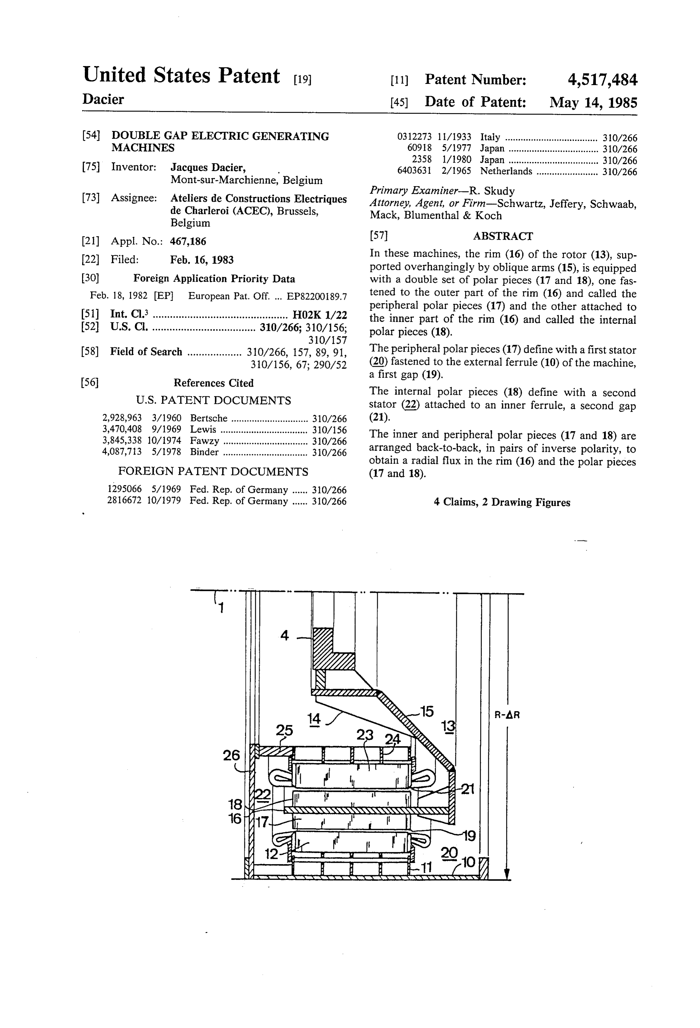
Belgium (21) Appl. No.: 467,186 57 ABSTRACT 22 Filed: Feb. 16, 1983 In these machines, the rim (16) of the rotor (13), sup ported overhangingly by oblique arms (15), is equipped 30) Foreign Application Priority Data with a double set of polar pieces (17 and 18), one fas Feb. 18, 1982 EP European Pat. Off. ... EP82200189.7 tened to the outer part of the rim (16) and called the peripheral polar pieces (17) and the other attached to 51) Int. Cl. ............................................... HO2K 1/22 the inner part of the rim (16) and called the internal 52 U.S. Cl. .................................... 310/266; 310/156; polar pieces (18).
(58) Field of Search ................... 310/266, 157, 89,91, The peripheral polar pieces (17) define with a first stator 310/156, 67; 290/52 (20) fastened to the external ferrule (10) of the machine, a first gap (19).
The internal polar pieces (18) define with a second stator (22) attached to an inner ferrule, a second gap 2,928,963 3/1960 Bertsche ... ... 310/266 (21).
3,470,408 9/1969 Lewis ........ ... 310/156
The inner and peripheral polar pieces (17 and 18) are 3,845,338 10/1974 Fawzy ... ... 310/266 4,087,713 5/1978 Binder ................................. 310/266 arranged back-to-back, in pairs of inverse polarity, to obtain a radial flux in the rim (16) and the polar pieces
FOREIGN PATENT DOCUMENTS (17 and 18).
28.16672 10/1979 Fed. Rep. of Germany ...... 310/266 4 Claims, 2 Drawing Figures
FRPPs
Sex Karacter arxxxx Ararasawaxy as
Page 2
Drawing sheet — no readable text.
Page 3
The invention will become more apparent from the
DOUBLE GAP ELECTRIC GENERATING figures hereinafter:
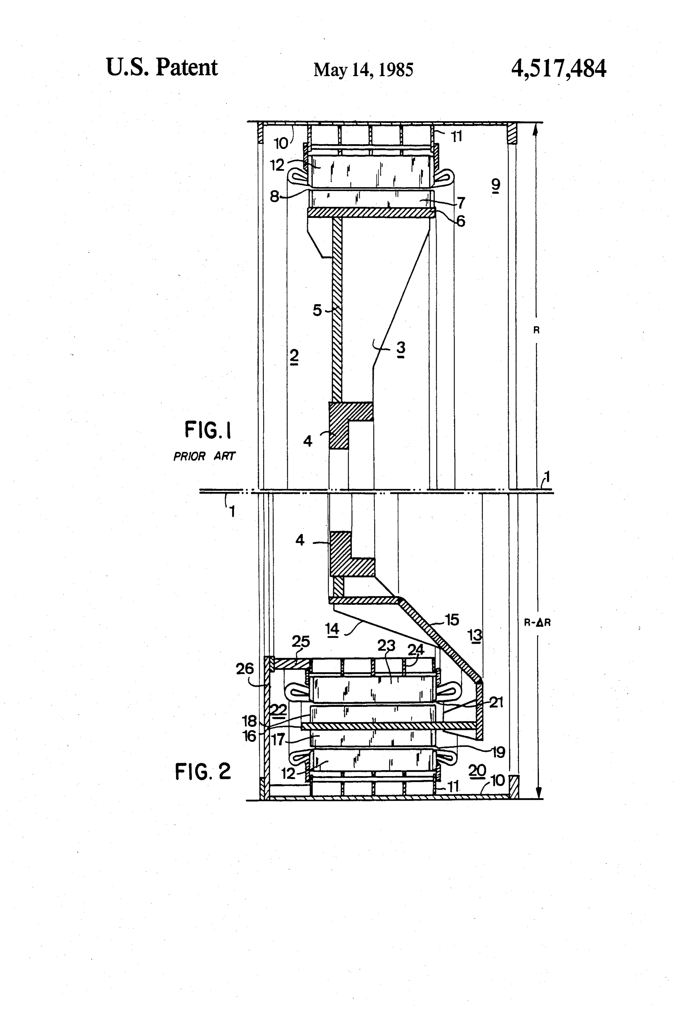
MACHINES FIG. 1 is a cross section showing the conventional disposition of a bulb group alternator.
For several years an increasing interest has been man- 5 FIG. 2 is a cross section of an alternator of the same ifested in research concerning the rational utilization of power constructed according to the invention claimed energy available by equiping low drops of rivers of the herein.
plains with hydroelectric power stations provided with In FIG. 1, an axis 1 represents the axis of a turbine groups of bulbs. These bulb groups were chosen be shaft joined to a rotor 2 of an alternator by means of a cause of their compactness resulting in important sav- 10 crosspiece 3 formed by a hollow hub 4 and radial arms ings in civil engineering work, greater simplicity in construction and installation and in regular and continu 5port fastened to the hub 4. The radial arms 5 serve to sup a rim 6 on which the polar pieces 7 are mounted.
ous forms of the hydraulic conduits which contributes Separated by a gap 8, the rotor 2 rotates in a stator 9. to an increase in the hydraulic performance of the tur consisting of a casing 10 holding a series of fastening bine. 15
These bulb groups are characterized by the position straps In 11 to support a magnetic hub 12.
this embodiment, the casing 10 also serves as the of the alternator mounted in the flow itself, in a narrow ferrule of the bulb group.
chamber of water.
FIG. 2 represents an embodiment of a double gap
In most cases, the turbine wheel is acting directly on alternator.
the alternator, the rotor of which is coupled with the 20 In FIG. 2, the axle 1 of the turbine shaft is coupled shaft of the turbine by means of a crosspiece comprising a hollow hub or core and a plurality of radial arms with a rotor 13 consisting of a crosspiece 14 formed by supporting the rim to which the polar pieces are resting. aporting, hollow hub 4 and a plurality of oblique arms 15 sup
Frequently the bulb ferrule serves as the casing of the whereof isoverhangingly, a rim 16 to the outer side stator of the alternator, the magnetic core of which is 25 pieces designated the peripheralofpolar fastened a plurality first magnetic polar supported by several holding straps distributed regu the inner side a plurality of second pieces 17 and to magnetic polar larly over the periphery of the casing.
In these embodiments, the maximum external diame pieces, designated the inner polar pieces 18. Separated by a peripheral gap 19, the peripheral polar ter of the chamber is more or less the same as that of the moving wheel. This fact leads to a very low filling rate 30 pieces 17 pass in front of a first wound stator called the of the internal part of the bulb, as the active parts are peripheral stator 20, the magnetic hub 12 whereof is located on the periphery and the center is occupied by supported against the ferrule 10 serving as the casing by the means joining the rim covered with poles and the means of the fastening straps 11.
shaft of the machine. The present invention is intended Similarly, the inner polar pieces 18, separated by an to remedy this poor utilization of the space available 35 inner gap 21, pass before a second stator designated the inside the bulb by equipping the machine with a second inner stator 22, comprising a magnetic core 23 mounted stator and providing the rotor with a second set of polar by means of fastening straps 24 on an inner casing 25, pieces. which in turn is connected with the ferrule 10 by means The machine claimed according to the invention thus of a bracing crown 26.
comprises a rotor equipped with a first set of polar 40 The peripheral or first polar pieces 17 and the inner pieces fastened to the periphery of the rim of the rotor or second polar pieces 18 mounted in either side of the and designated the peripheral polar pieces and a second rim 16 are fastened to the latter in equal number, form set of polar pieces fastened to the internal part of the rim ing radial pairs, so that first and second polar pieces of and designated the internal polar pieces. opposing signs or polarities are placed back-to-back The peripheral polar pieces are passing in front of a 45 respectively in order to obtain a harmonious flow of the first stator called the peripheral stator, the casing of magnetic flux.
which is the ferrule of the bulb. The peripheral polar, The magnetic hub 12 has a first diameter; core 23 has pieces are separated from the peripheral rotor by a first a second diameter, less than the first diameter; and an gap, called the peripheral gap. nular rim 16 has a third diameter, less than the first The internal polar pieces pass in front of a second 50 diameter and greater than the second diameter. stator called the inner stator, the casing of which is In this double gap machine, the flux is thus radial in supported by a solid crown braced against the ferrule of its inner polar pieces 18, in the rim 16 and in the periph the bulb. The internal polar pieces are separated from eral polar pieces 17 and tangential in the magnetic hub the inner stator by a second gap called the inner gap. 12 and core 23. An embodiment leading to a particu By the creation in this manner of a second gap, the 55 larly economical application of this configuration is power of the machine is greatly increased for the same relative to a bulb group alternator as it results in a re space occupied, or, with an equal power, the diameter duction of the diameter of the bulb group. of the bulb is substantially reduced. This latter possibil This new configuration may further be applied to ity is of dual importance; it increases the number of vertical axis Kaplan turbines, the rotating velocity of groups located on the same dam, and it reduces the cost 60 which is not very high. In this case, the axle of the of civil engineering work by reducing the transverse alternator is also vertical and the inner stator 22 is in size of the installation by virtue of the decrease in the stalled on site after the mounting of the turbine wheel length of the bulb, while maintaining the same constric by passing it through the peripheral stator 20. tion of the fluid flow, This machine with its double stators has the advan In this novel embodiment, the rim, equipped with 65 tage of being capable of continued operation in case of two sets of polar pieces: the peripheral polar pieces and damage to the winding of one of the two stators. the internal polar pieces, is supported overhangingly by The configuration that is the object of the present means of oblique arms connected with the hub. invention obviously is also applicable to a reversible
Page 4
group, such as an alternator combined with a tubine a plurality of second polar pieces disposed on the pump. inner face of said rim so as to form a second I claim: annular gap between the plurality of said second 1. An electric generating machine having an outer polar pieces and the second stator, the second casing, an inner casing, and a shaft, comprising: annular gap being concentric with the first annu a first stator comprising a first annular wound mag lar gap.
netic hub having a first diameter, said first stator 2. An electric generating machine as claimed in claim being mounted within the outer casing; 1, wherein the inner casing is connected to the outer casing by means of a bracing crown.
a second stator comprising an annular wound mag 10 3. An electric generating machine as claimed in claim netic core having a second diameter less than the 1, wherein the number of the first polar pieces equals first diameter mounted about the inner casing so the number of the second polar pieces and wherein said that the second stator is disposed within and con first and second polar pieces are attached to the outer centric with the first stator; and face and the inner face, respectively, in radial pairs, a rotor comprising: 15 Oriented with opposing magnetic polarities facing each an annular rim having a third diameter less than the other.
first diameter and greater than the second diame 4. An electric generating machine as claimed in claim ter joined to the shaft, the rim having an inner thewherein 2, the number of the first polar pieces equals number of the second polar pieces and wherein said face and outer face; 20 first and second polar pieces are attached to the outer a plurality of first polar pieces disposed on the face and the inner face, respectively, in radial pairs, outer face of said rim so as to form a first annular oriented with opposing magnetic polarities facing each gap between the plurality of said first polar other.
pieces and the first stator; and xk ck -k ck sk
Provenance
- Collection
- Cited prior art
- Original PDF
- patentimages.storage.googleapis.com →
- Filed
- 1983-02-16
- Pages
- 4
- Method
- pdftotext (the PDF's own text layer) + pdftoppm 300dpi page scans
- Source
- Google Patents bibliographic record
- Granted
- 1985-05-14
- Inventors
- Jacques Dacier; Ateliers de Constructions Electriques de Charleroi SA
- Transcribed from
- patentimages.storage.googleapis.com →