patent · US3250926
Ventilated motor
10 May 1966
Page 1
Drawing sheet — no readable text.
Page 2
Drawing sheet — no readable text.
Page 3
United States Patent Office 3,250,926 Patented May 10, 1966
illustrating the construction of the cover, housing and
VENTLATED MOTOR
mounting base.
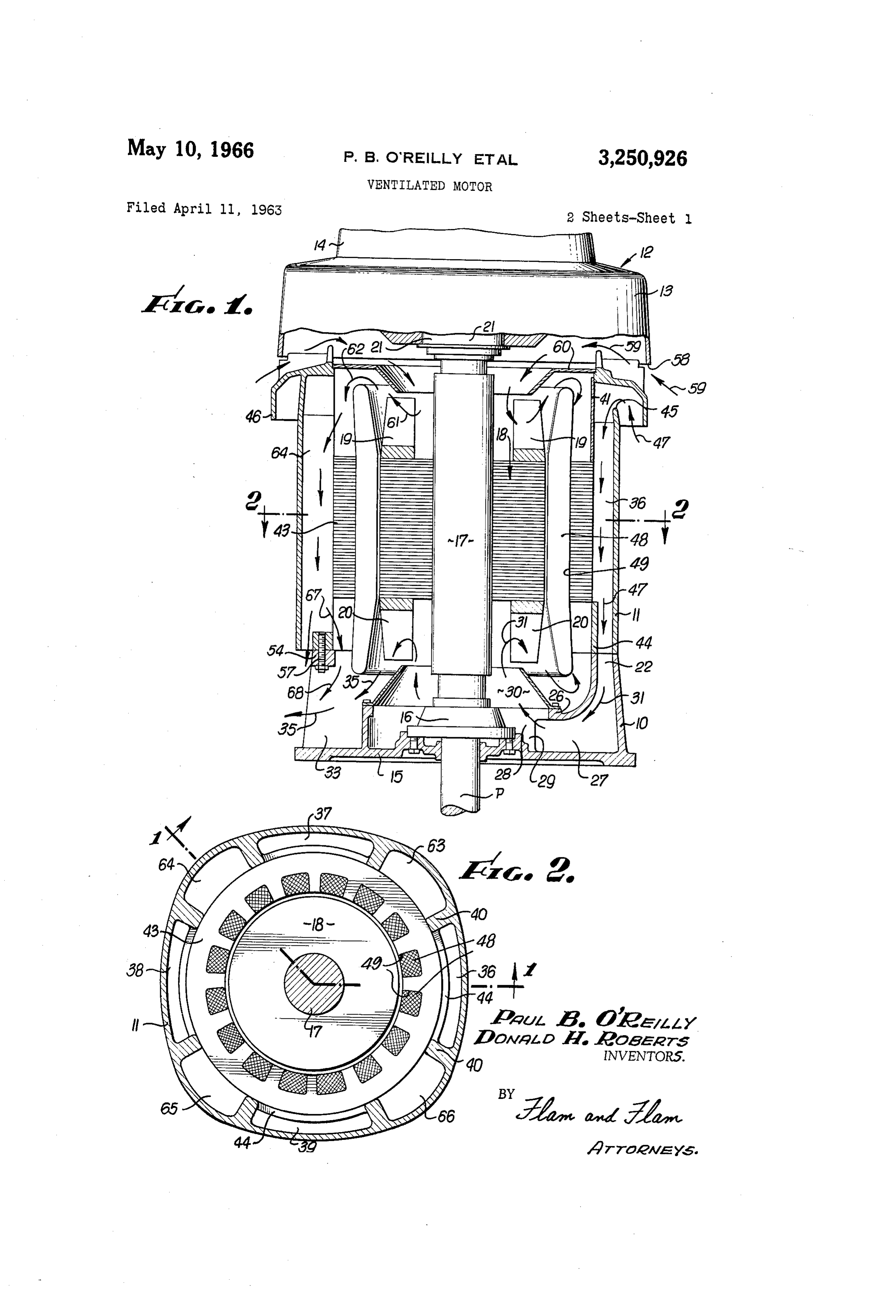
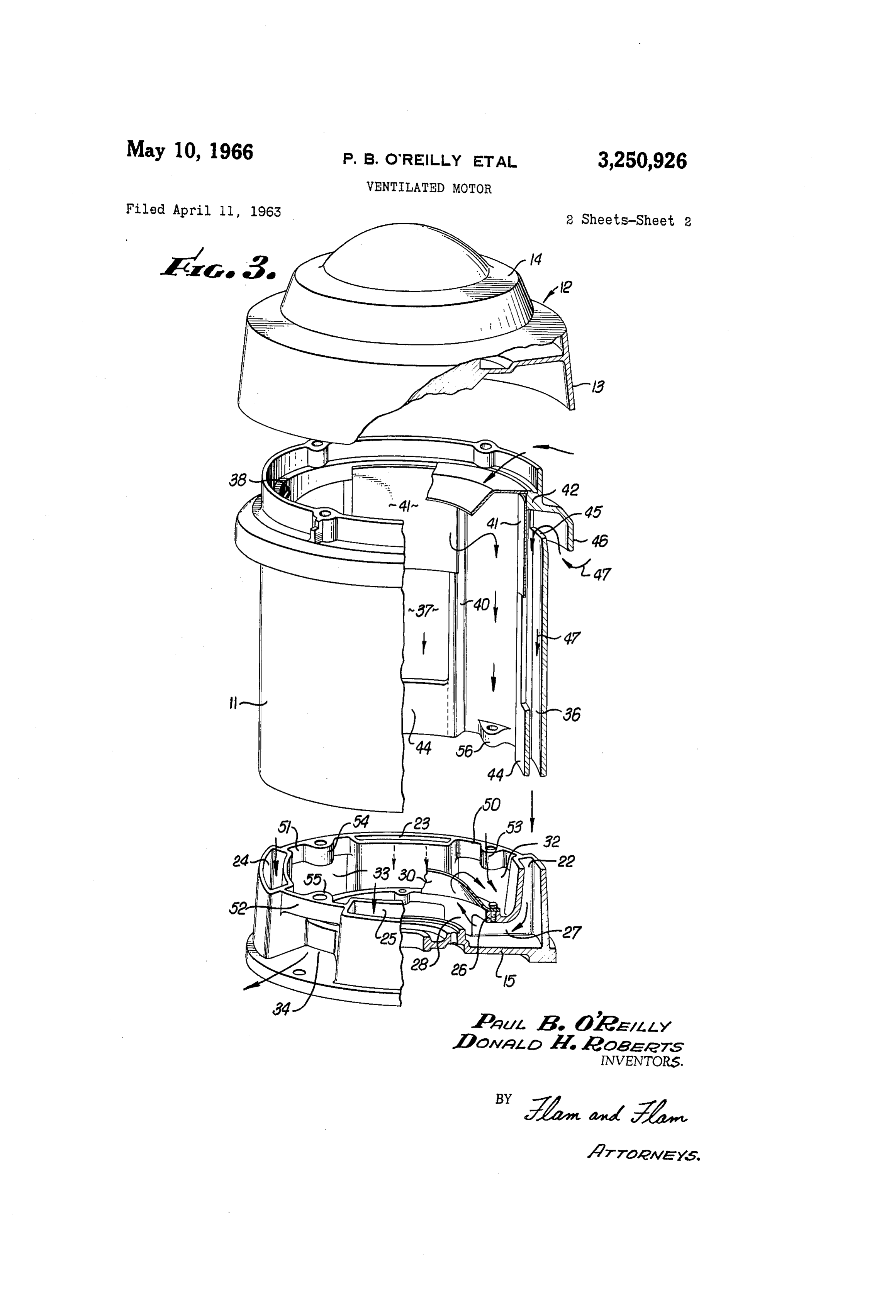
Paul B. O'Reilly, Pico-Rivera, and Donald H. Roberts, The motor structure shown in the drawings includes a Los Angeles, Calif., assignors to Emerson Electric Co., 5 mounting base 10, a central housing section 11 and a a corporation of Missouri cover 12 that may be made as precision castings. Filed Apr. 11, 1963, Ser. No. 272,353 The cover 12 may include two parts, a lower cowl part 12 Claims. (C. 310-60) 13 and a cap part 4 which is readily detachable from the cowl part 13.
This invention relates to a vertical motor, such as for above ground use in driving the vertical shaft of a pump. 0 to The mounting base 10 has a circular plate 15 adapted be secured to the upper surface of the pump head. A
Particularly this invention relates to a ventilation system lower bearing structure 16 is supported at the center of for cooling. the wall 15.
In small motors, rated, for example, under 10 H.P., A hollow shaft 17 of the motor structure projects ver adequate cooling may be provided by passing a single tically upwardly from the bearing 16. The motor shaft stream of air vertically through the motor. For example, 17 carries a rotor structure 18. The rotor structure 18 cold air may enter the housing from above the rotor, and in this instance includes integrally cast aluminum parts be urged about the thrust bearing, windings, then down providing fan structures 19 and 20 at opposite ends. The wardly about the stator, and perhaps through the rotor, rotor and fan may be made in other manners. These fan then about the windings to outlet openings at the bottom of the housing. Fan blades cast integrally with the rotor 20 to conduct heat from the rotor toof the structures not only induce currents air, but also serve air current so may be used to create this air stream. created.
. In larger motors, rated, say, 10 H.P. and up, the fore The upper end of the hollow shaft 17 is supported by going method of circulating air is not entirely effective. a thrust bearing structure 21. The thrust bearing struc Thus the air may be unduly heated before its reaches ture 21 is supported by radial ribs or webs formed in the the parts located at the lower end of the rotor. Of cover 12.
course, the physical size of the housing could be in The pump shaft P extends upwardly through the bear creased, but this is not desirable. One solution has been ing 16, the hollow shaft 17 and the upper bearing 21 for to provide two different air streams, one for the upper connection to the upper end of the hollow shaft 17. end of the motor and one for the lower end. The difficul The mounting base 10 provides a number (in this in ty with this arrangement has been that the intake for the 30 stance four) of equiangularly located air ducts 22-25 for lower air stream is too close to the exhaust, and the inlet cooling the lower bearing 16 as well as the lower end of air is preheated, reducing efficiency. the motor structure. The ducts 22-25 have narrow gen An object of this invention is to provide an improved erally arcuate upper inlet openings located at the pe ventilation system, especially adapted for use with motors riphery of the upper edge of the base 10. of high power rating, and in which both ends of the motor 35 The outer walls of the ducts 22-25 extend generally ver are effectively cooled. tically from the periphery of the base plate 15. The inner Another object of this invention is to provide a motor walls of the ducts 22-25 curve inwardly and terminate at ventilation system of this character in which two paral a common circular ring 26. The ring 26 is located above lel paths are provided for cooling the upper and lower the base plate 15 and in spaced encompassing relationship ends of the motor respectively, but in which the inlets for 40 to the lower bearing 16. The side walls 27 of the ducts both paths are located at the upper end of the motor while 22-25 are generally L-shaped, and also terminate inward the outlets are located at the lower end, ensuring maxi ly at the position of the circular ring 26. Arcuate walls mum efficiency. In order to accomplish the foregoing 28 join the inner ends of the side walls of adjacent ducts. function, the motor housing is uniquely constructed to A circular channel 29 (FIG. 1) is thus formed about the provide appropriate air ventilation paths. 45 lower bearing that communicates with the ducts 22-25. . Another object of this invention is to provide a motor A frusto-conical deflector plate 30 has a base flange ventilation system which by virtue of a unique arrange mounted upon the circular ring 26. The upper open end ment ensures that the volume of air circulated is sub of the deflector plate 30 terminates just short of the fan
structure 20 and registers with the space on the inner side
Still another object of this invention is to provide a of the fan structure 20. The fan structure 20 operates to motor ventilation system in which the temperature of the induce downward and inward flow of air in the ducts as frame is quite low. indicated by the arrows 31. This air is caused to sweep This invention possesses many other advantages, and past the lower bearing structure 16 and upwardly through has other objects which may be made more clearly appar the deflector plate 30. The air can then pass along the ent from a consideration of one embodiment of the in 55 top of the plate 30 to spaces between the ducts 22-25 vention. For this purpose, there is shown a form in the which provide exhaust openings 32, 33, 34, etc. (FIG. 3) drawings accompanying and forming a part of the present and as indicated by the arrows 35 in FIGS. 1 and 3. specification, and which drawings, unless as otherwise Ducts 36, 37, 38 and 39 formed in the housing sec indicated, are true scale. This form will now be described 60- tion 11 respectively extend the inlets of the ducts 22-25 in detail, illustrating the general principles of the inven of the mounting base 10 upwardly and away from the ex tion; but it is to be understood that this detailed descrip haust openings 32, 33, 34, etc. The outer walls of the tion is not to be taken in a limiting sense, since the scope ducts 36-39 are formed by the common peripheral wall of this invention is best defined by the appended claims. of the housing section 11. The side walls of the ducts Referring to the drawings: 36-39 are formed by vertical ribs 40 on the inside of the 65 housing section.
FIGURE 1 is a fragmentary revolved axial sectional The inner walls of the ducts 36-39 are formed in view of a motor incorporating the present invention;
FIG. 2 is a transverse sectional view taken along the vided parts.
three
The first or upper part of each duct is pro individual arcuate plate 41 having sides over plane corresponding to line 2-2 of FIG. 1, FIG. 2 illus lying the inner edges of the ribs 40. The upper part of trating by line 1-1 the axial sectional planes of FIG. 1; 70 the plate 41 is attached by suitable means to the inner and surface of a circular top ring 42 cast integrally with the FIG. 3 is an exploded fragmentary sectional view housing 11.
Page 4
The second or intermediate parts of the inner walls of and communicating with the fan element and winding of the ducts 36-39 are formed by the peripheral sur ends at the other end of the housing, said first air passage face of the stack of stator laminations 43 which fit having an exhaust adjacent said other end of the hous against the ribs 40. The top lamination of the stack 43 ing; and means forming a second air passage in the hous abuts or closely approaches the lower end edges of the ing having an intake opening adjacent said one end and plates 41. communicating with the fan element and winding ends at The third or lower section of the inner wall of each said one end of the housing, said second air passage hav of the ducts is formed by an arcuate wall 44, cast in ing an exhaust adjacent the said other end of the hous tegrally with the housing section 1. The sides of the ing; said fan elements being arranged respectively to in walls 44 merge with the lower ends of the ribs 40, and the 10 duce flow of air into said intake openings and out of said upper edges of the walls 44 are located at the level of exhausts whereby both intake openings are located re the bottom lamination of the stack 43. mote from both exhausts thus to minimize recirculation The outer wall of the housing section 1 has openings of exhausted air.
45 located just beneath the top ring 42 to form intakes 2. The combination as set forth in claim 1 wherein to the ducts 36-39. A cowl 46 projects outwardly from 15 said dynamoelectric machine is provided with bearing the ring 42 and over the openings 45 suitable to shield structures for opposite ends of said shaft, said bearing them. structures being respectively, located adjacent said fan The lower ends of the ducts 36–39 register with the elements and exposed respectively in the said air passages upper ends of the ducts 22–25, there being companion respectively.
mutually engaging surfaces of the mounting base 10 and 20 3. In a dynamoelectric machine: a housing; said hous housing section 1. The ducts 36-39 thus form upward ing having a number of angularly spaced ducts extending extensions of the ducts 22-25 and serve to supply cool longitudinally along the periphery of the housing, there air from the region spaced substantially from the exhaust being channels between the ducts opening inwardly of the openings 32, 33 and 34. The air passing through the housing; the ends of said ducts opening at corresponding ducts 36-39, as indicated by the arrows 47, produces a ends exteriorly at one end of the housing; a stator mounted cooling effect on the stator lamination stack 43. in the housing and extending across the central portions This air, as indicated at the arrows 35, also passes of said channels; said channels having exhaust openings along the lower ends of windings 48 accommodated in at the other end of the housing for conducting air out the slots 49 of the stator lamination stack 43. wardly of the housing; windings carried by the stator and In order to secure the housing section to the mount 30 having opposite ends projecting beyond the stator; a ing base 10, webs 50, 51, 52, etc. are provided that ex rotor structure including a shaft, said rotor structure tend between the walls forming the ducts 22-25. These having fan elements at opposite ends and located adjacent webs extend across the top of the openings 32, 33, 34, said winding ends respectively; means forming an intake etc. and have inwardly extending bosses 53, 54, 55, etc. opening at said one end of said housing and communicating that register with companion bosses 56, etc. formed on 35 with the fan element adjacent said one end of said hous the housing section 11. The top edges of the WebS 59, ing for movement of air past the corresponding winding 51 and 52 engage the lower edges of the housing section ends and into said channels; and means forming passages 11 at the areas between the ducts 36-39. Suitable fas from the other corresponding ends of said ducts and teners 57 extending upwardly through the bosses Secure communicating with the fan element at the other end of the parts together. - 40 said housing for movement of air past the corresponding A second current of air is provided for cooling the winding ends and through the exhaust openings of said bearing structure 21, the upper end of the rotor, the wind channels; said fan elements being arranged respectively ings at the upper end of the stator stack 43 and also the to induce flow of air currents in the same direction rela stator laminations. This current of air enters the cowl tive to said exhaust openings of said channels whereby part 13 of the cover 12 above the cowl 46 formed on the 45 influent air and effluent air are widely separated thus to . housing section 11. Thus, the circular edge 58 of the minimize recirculation.
cowl part 13 is spaced vertically above the cowl 46 and 4. The combination as set forth in claim 3 in which defines an annular intake, as indicated by the arrows the ducts are substantially arcuate in cross section, periph 59. The air so entering passes above the circular wall eral portions of the stator forming parts of the walls of the 42 of the housing section 11 and thence downwardly 50 ducts.
between the thrust bearing 21 and the top Surface of a 5. The combination as set forth in claim 3 wherein said conical plate 60. The plate 60 is attached at its periphery dynamoelectric machine is provided with bearing struc to a shoulder formed in the circular ring 42. The air tures for opposite ends of said shaft, said bearing struc then passes to the space within the blades 19, past the tures being respectively located adjacent said fan ele upper ends of the windings 48 and along the under Sur ments and exposed to the currents of air induced thereby. face of the deflector plate 60, as indicated by the arrows 6. The combination as set forth in claim 3 in which 61 and 62. The air then passes to channels 63, 64, 65 said winding ends extend in spaced exterior encompass and 66 located between the ducts 36-39. ing relationship to the corresponding fan elements; a The upper ends of the channels 63-66 communicate first conical deflector plate having a rim attached to said with the space beneath the baffle plate 60. The stack 60 housing and having a free inner edge terminating adjacent of stator laminations 43 cover the intermediate portionsthe winding ends and fan element at said one end of of the channels 63–66, but the lower ends of the channels said housing, the outer side of said first deflector plate are open and communicate with a circular space beneath communicating with said intake opening, and the inner the stack of laminations 43 and the lower ends of the side communicating with said channels, said deflector windings 48. The air can then pass outwardly through 65 plate forming a baffle between said channels and said the openings 32, 33, 34 and 35, as indicated by the ar intake opening as well as guiding the current of air along rows 67 and 68. the winding ends; and a second conical deflector plate The inventors claim: having a rim attached to said housing and having a free 1. In a dynamoelectric machine: a housing; a stator inner edge terminating adjacent the winding ends and fan. mounted by the housing; windings carried by the stator element at said other end of said housing, the outer side and having opposite ends projecting beyond the stator; 70 of said first deflector plate communicating with said pas a rotor structure in the stator, said rotor structure includ sages, and the inner side communicating with said exhaust ing a shaft, said rotor structure having fan elements openings.
at opposite ends; means forming a first air passage in the 7. The combination as set forth in claim 6 together housing having an intake opening adjacent one end there with bearing structures for the ends of said shaft, and lo
Page 5
cated in spaced relationship to said deflector plates on 11. In a motor structure: a housing having a mount the outer sides thereof. ing base adapted to be secured to a pump head or the like; 8. In a motor structure: a housing having a mount said mounting base having wall means forming a plurality ing base adapted to be secured to a pump head or the of angularly spaced ducts extending downwardly along like; said mounting base having wall means forming a the periphery of the mounting base and thence inwardly plurality of angularly spaced ducts extending downwardly toward the center thereof; said mounting base having a along the periphery of the mounting base and thence ring beneath which the ducts terminate, there being walls inwardly toward the center thereof; said mounting base between the inner ends of said ducts and beneath the ring having a ring beneath which the ducts terminate, there to form a circular space; said housing having upward inlet being walls between the inner ends of said ducts and 0. extensions of said ducts; the spaces between the ducts at beneath the ring to form a circular space; said housing the region of the mounting base forming exhaust openings having upward inlet extensions of said ducts; the spaces from the housing there being channels between the inlet between the ducts at the region of the mounting base form extensions of the duct opening within the housing and ing exhaust openings from the housing. communicating with said exhaust openings; a stator struc 9. In a motor structure: a housing having a mounting 5 ture in the housing and extending across the intermediate base adapted to be secured to a pump head or the like; portions of said channels, said structure including wind said mounting base having wall means forming a plurality ings having ends projecting at opposite ends of the stator of angularly spaced ducts extending downwardly along Structure;
the periphery of the mounting base and thence inwardly ends of saidmeans forming intake openings for the upper channels; a rotor structure in the housing, and toward the center thereof; said mounting base having a 20 having a shaft and fan structures at opposite ends; a de ring beneath which the ducts terminate, there being walls flector plate mounted on said ring and having an opening between the inner ends of said ducts and beneath the located adjacent the fan structure at the lower end of said ring to form a circular space; said housing having upward motor;
inlet extensions of said ducts; the spaces between the ducts base andandlocated a bearing structure carried by said mounting in inwardly spaced relationship to said at the region of the mounting base forming exhaust open 25 ring and said deflector plate.
ings from the housing there being channels between the 12. In a motor structure: a housing; wall means form inlet extensions of the duct opening within the housing ing a plurality of angularly spaced and communicating with said exhaust openings; a stator the exterior of said housing, thereducts extending along being channels ex structure in the housing and extending across the inter tending between the ducts and opening within mediate portions of said channels; and means forming in 30 ing; a stator structure and a rotor structure in thethe hous housing;
take openings for the upper ends of said channels.
10. In a motor structure: a housing having a mount means forming intake openings for the ducts at one ing base adapted to be secured to a pump head or the end of the housing, and exhaust openings for the channels at the other end of the housing; passage forming means like; said mounting base having wall means forming a serially plurality of angularly spaced ducts extending downwardly 35 extendingjoining the ducts and the exhaust openings and past the said rotor and stator structures at said along the periphery of the mounting base and thence in other end of said housing; passage forming means joining wardly toward the center thereof; said mounting base hav the ing a ring beneath which the ducts terminate, there being the channels and the intake openings and extending past rotor and stator structures at said one end of said walls between the inner ends of said ducts and beneath housing; and a pair of fan elements carried at opposite the ring to form a circular space; said housing having 40 ends of the rotor structure and respectively interposed in upward inlet extensions of said ducts; the spaces between said passage means, said fan elements being arranged the ducts at the region of the mounting base forming ex respectively to induce air flow in the same directions in haust openings from the housing there being channels be-, said passages whereby the intake openings are located tween the inlet extensions of the duct opening within the remote from both exhaust openings thus to minimize housing and communicating with said exhaust openings; 45 recirculation of exhausted air. a stator structure in the housing and extending across the intermediate portions of said channels, said structure in References Cited by the Examiner cluding windings having ends projecting at opposite ends of the stator structure; means forming intake openings UNITED STATES PATENTS for the upper ends of said channels; a rotor structure in 50 2,357,923 9/1944 Anderson ----------- 310-60 the housing, and having a shaft and fan structures at op posite ends; and a deflector plate mounted on said ring MILTON O. HERSHFIELD, Primary Examiner.
and having an opening located adjacent the fan struc L. L. SMITH, Assistant Examiner.
ture at the lower end of said motor.
Provenance
- Collection
- Cited prior art
- Original PDF
- patentimages.storage.googleapis.com →
- Filed
- 1963-04-11
- Pages
- 5
- Method
- pdftotext (the PDF's own text layer) + pdftoppm 300dpi page scans
- Source
- Google Patents bibliographic record
- Granted
- 1966-05-10
- Inventors
- Paul B O'reilly; Donald H Roberts; Emerson Electric Co
- Transcribed from
- patentimages.storage.googleapis.com →