patent · US5798632
Variable speed wind turbine generator with zero-sequence filter
25 August 1998
Page 1 — bibliographic record
United States Patent (19) 11 Patent Number: 5,798,632 Muljadi 45 Date of Patent: Aug. 25, 1998 54) VARIABLE SPEED WINDTURBINE 5.187.427 21993 Erdman ................................... 323/207 GENERATOR WITH ZERO-SEQUENCE 5.225,712 7/1993 Erdman ... ... 290/.44 FILTER 5.289,041 2/1994 Holley ..... ...... 290/.44 5,652.485 7/1997 Spiegel et al. .......................... 38/147 75) Inventor: Eduard Muljadi, Golden. Colo.
Primary Examiner-Steven L. Stephan 73) Assignee: Midwest Research Institute. Kansas Assistant Examiner-Nicholas Ponomarenko City, Mo. Attorney, Agent, or Firm-Ken Richardson
(22 Filed: Jun. 6, 1997 A variable speed wind turbine generator system to convert mechanical power into electrical power or energy and to
Related U.S. Application Data recover the electrical power or energy in the form of three phase alternating current and return the power or energy to 63) Continuation of Ser. No. 503.818, Jul. 18, 1995, abandoned. a utility or other load with single phase sinusoidal waveform at sixty (60) hertz and unity power factor includes an (51) Int. C. r. H02P 9/00 excitation controller for generating three phase commanded 52 U.S. C. ................................. 322/29; 322/20: 290/44: current, a generator, and a zero sequence filter. Each com 290/55 manded current signal includes two components: a positive 58) Field of Search .................................. 322/29, 20, 28: sequence variable frequency current signal to provide the 290/44, 55 balanced three phase excitation currents required in the stator windings of the generator to generate the rotating 56 References Cited magnetic field needed to recover an optimum level of real
hertz current signal to allow the real power generated by the 4.087,698 5/1978 Myers ....................................... 307/84 generator to be supplied to the utility. The positive sequence 4,189,648 2/1980 Harner ... 290,44 current signals are balanced three phase signals and are 4,218,732 8/1980 Lafuze ....... 363/60 prevented from entering the utility by the zero sequence 4.228,361 10/1980 Jacobs et al. .. filter. The zero sequence current signals have zero phase 4,357,542 11/1982 Kirschbaum ... displacement from each other and are prevented from enter 4,695,736 9/1987 Doman et al. . 290/44 ing the generator by the star connected stator windings. The 4,794,316 12/1988 Uchino et al. . 322/47 4,906,060 3/1990 Claude ....... 322/29 zero sequence filter allows the zero sequence current signals 4992,920 2/1991 Davis ................ 363/36 to pass through to deliver power to the utility. 5,083,039 1/1992 Richardson et al. ... 290/44 5,155.375 10/1992 Holley ....................................... 29044 32 Claims, 14 Drawing Sheets
Excitation
Controller
Sensor
Page 2
Drawing sheet — no readable text.
Page 3
Drawing sheet — no readable text.
Page 4
Drawing sheet — no readable text.
Page 5
Drawing sheet — no readable text.
Page 6
Drawing sheet — no readable text.
Page 7
Drawing sheet — no readable text.
Page 8
Drawing sheet — no readable text.
Page 9
Drawing sheet — no readable text.
Page 10
Drawing sheet — no readable text.
Page 11
Drawing sheet — no readable text.
Page 12
Drawing sheet — no readable text.
Page 13
Drawing sheet — no readable text.
Page 14
Drawing sheet — no readable text.
Page 15
Drawing sheet — no readable text.
Page 16
WARIABLE SPEED WIND TURBINE ambient wind velocity conditions are, of course, an obvious GENERATOR WITH ZERO-SEQUENCE solution. provided they can be made to produce constant FILTER sixty (60) hertz or other standard frequency AC electricity. The output power from a variable speed wind turbine
This application is a continuation of application Ser. No. 5 generator depends largely on the velocity of the wind, the 08/503,818, filed Jul. 18, 1995, now abandoned. revolutions-per-minute (RPM) of the rotating turbine and The United States Government has rights in this inven the rotating rotor in the generator, and the frequency of the tion under Contract No. DE-AC 36-83 CH 10093 between the current signals flowing in the stator windings of the genera U.S. Department of Energy and the National Renewable tor. Since the wind turbine shaft rotates the electric generator Energy Laboratory, a Division of Midwest Research Insti 10 shaft and the rotor and the revolutions-per-minute (RPM) of tute. the rotating wind turbine is directly proportional to the
BACKGROUND OF THE INVENTION
ambient wind velocity, for a specific ambient wind velocity.
there is a specific RPM of the rotating turbine and the 1. Field of the Invention rotating rotor. For a specific RPM of the rotating turbine and This invention relates generally to a generator system for 15 the rotating rotor, there is a specific frequency in hertz of the converting wind power into electrical power to be delivered electric currents flowing in the stator windings of the gen to a public utility and, more particularly, to a variable speed erator that maximizes the generated power. Therefore, while wind turbine generator system in which electrical power in a variable speed wind turbine system operating in varying the form of three phase alternating current is converted and wind velocity conditions can generate more electric power delivered to a utility with a single phase, sinusoidal wave than a constant speed turbine generator, it requires a more form at sixty (60) hertz and unity power factor. complicated electrical system, since the generated electricity 2. Description of the Prior Art will have a variable frequency that needs to be converted to Wind power has been used for ages to pump water, grind utility,(60) sixty
Some hertz before the electric power is delivered to a prior art variable speed wind turbine generator grain, and more recently to generate electricity. Such historic 25 systems use power uses of wind power, however, have been primarily in appli generated power to switches to covert the frequency of the cations where a single wind machine operated alone for the quency. For example, U.S. Pat.hertzsixty (60) or other standard fre
benefit of one or a small number of users. There is now more interest in developing wind power generator systems in switches. Richardson et al. discloses such a system that uses twelve which electricity produced by a single wind power generator power It is desirable, however, to reduce the number of switches can be supplied to utility power grids. However, when the to reduce the complexity and the supporting electronic circuitry so as electrical power generated by a wind power system is to be to and cost of the generator system, supplied to a utility grid, then the supplied power is required reduce the physical size of the wind generator system, and to have a constant frequency, e.g., sixty (60) hertz, that is to increase the reliability and useful life of the generator synchronized to and in phase with the frequency of the 35 system. In addition, it is desirable to have a generator system utility lines. The entire electrical infrastructure of the United that adjusts the frequency of the currents supplied to the stator windings of the generator so as to optimize the power
States and most industrial, commercial, and even home generated. Finally, the generator system should supply the electrical equipment is designed on the sixty (60) cycles generated power per-second (hertz) frequency standard, so any electric power a sixty (60) hertztoor the utility at unity power factor and with other standard frequency in a sinusoidal supplied by utility company power grids in the United States waveform that is synchronized has to conform to that standard. Other countries or regions in the utility so as to maximizewith the phase of the signals the power delivered to the have different frequency standards, for example, fifty (50) utility by the generator. Unity power factor for purposes of hertz in many European countries. The different frequency this invention is defined as a power factor of one (1), which standards of different countries are not significant to this is obtained when the current and the voltage signals in a invention, but the difficulties of generating and supplying 45 circuit are completely in phase. electric power efficiently from wind to a specific frequency standard without implementing mechanisms and techniques SUMMARY OF THE INVENTION that compromise power generation efficiency in order to Accordingly, it is a general object of this invention to deliver at a specific frequency has been an ongoing problem. provide a variable speed turbine generator system that Conversion of wind power into electrical power is accom 50 generates an optimum level of power during varying wind plished in most wind power systems by connecting a wind velocity conditions and delivers the generated power to a driven turbine to the shaft of an electric generator, usually an utility at unity power factor and with a sixty (60) hertz or alternating current AC induction generator. Obtaining the other standard frequency in a sinusoidal waveform that is required sixty (60) hertz or other standard frequency has in synchronized with the phase of the signals in the utility. the past been accomplished by limiting the generator to a 55 It is another general object of this invention to provide a constant rotational speed, which, unless a variable speed variable speed wind turbine generator system that minimizes transmission is used in the generator, requires that the wind the number of power switches and the complexity of the turbine also rotate at a constant speed, regardless of the wind supporting electronic circuitry required to create the neces velocity. Requiring the constant speed operation of a wind sary current signals to excite the stator windings in the turbine in variable wind velocity conditions, however, limits generator and the necessary current signals to deliver the its energy conversion efficiency, thus also limiting the elec generated power to the utility.
tric power generated by the system for delivery to the utility. Additional objects, advantages, and novel features of the The rotational speed of the rotating wind turbine needs to be invention shall be set forth in part in the description that variable and proportional to the wind velocity in order to follows, and in part will become apparent to those skilled in obtain maximum power output from the generator. 65 the art upon examination of the following or may be learned Variable speed wind turbine generators in which the by the practice of the invention. The objects and the advan turbine rotational speed can vary according to varying tages may be realized and attained by means of the instru
Page 17
mentalities and in combinations particularly pointed out in embodiments of the present invention, and together with the the appended claims. descriptions serve to explain the principles of the invention. To achieve the foregoing and other objects and in accor In the Drawings:
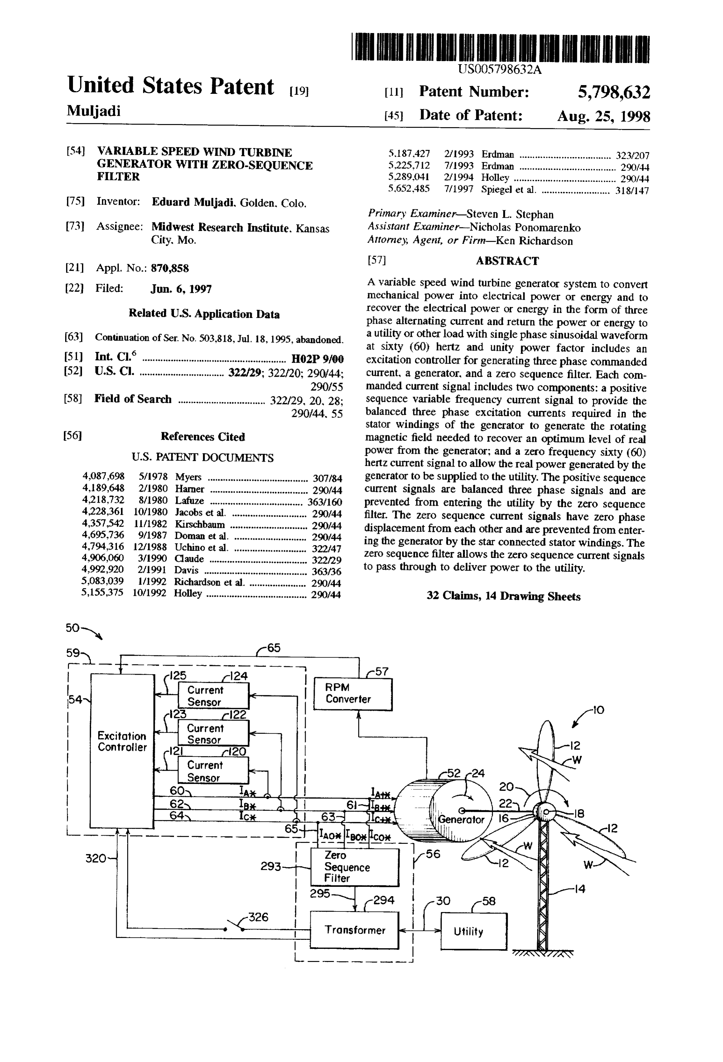
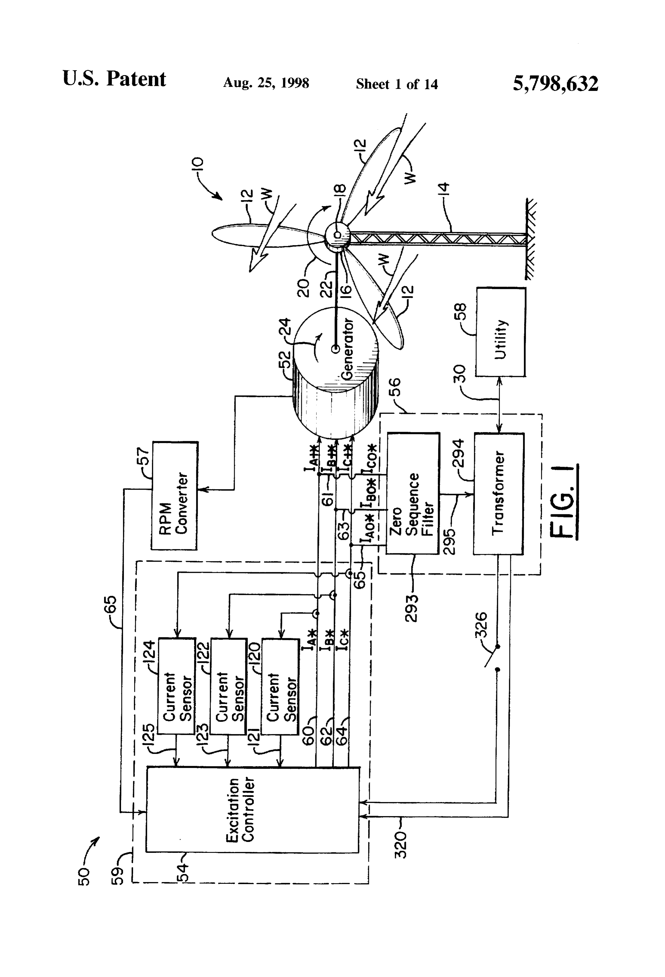
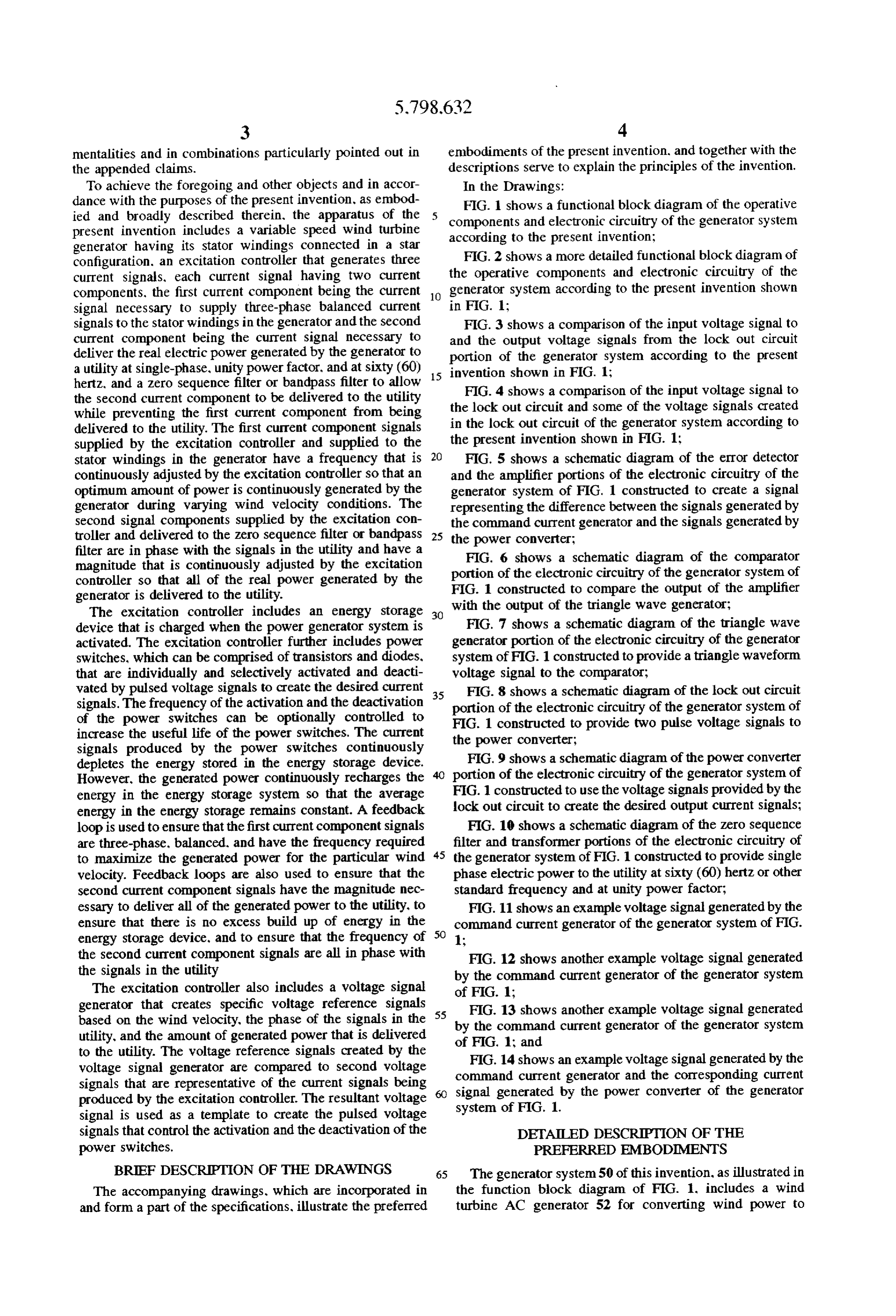
dance with the purposes of the present invention, as embod FIG. 1 shows a functional block diagram of the operative ied and broadly described therein, the apparatus of the components and electronic circuitry of the generator system present invention includes a variable speed wind turbine according to the present invention; generator having its stator windings connected in a star configuration. an excitation controller that generates three FIG.2 shows a more detailed functional block diagram of current signals, each current signal having two current the operative components and electronic circuitry of the components, the first current component being the current generator system according to the present invention shown signal necessary to supply three-phase balanced current in FIG. 1:
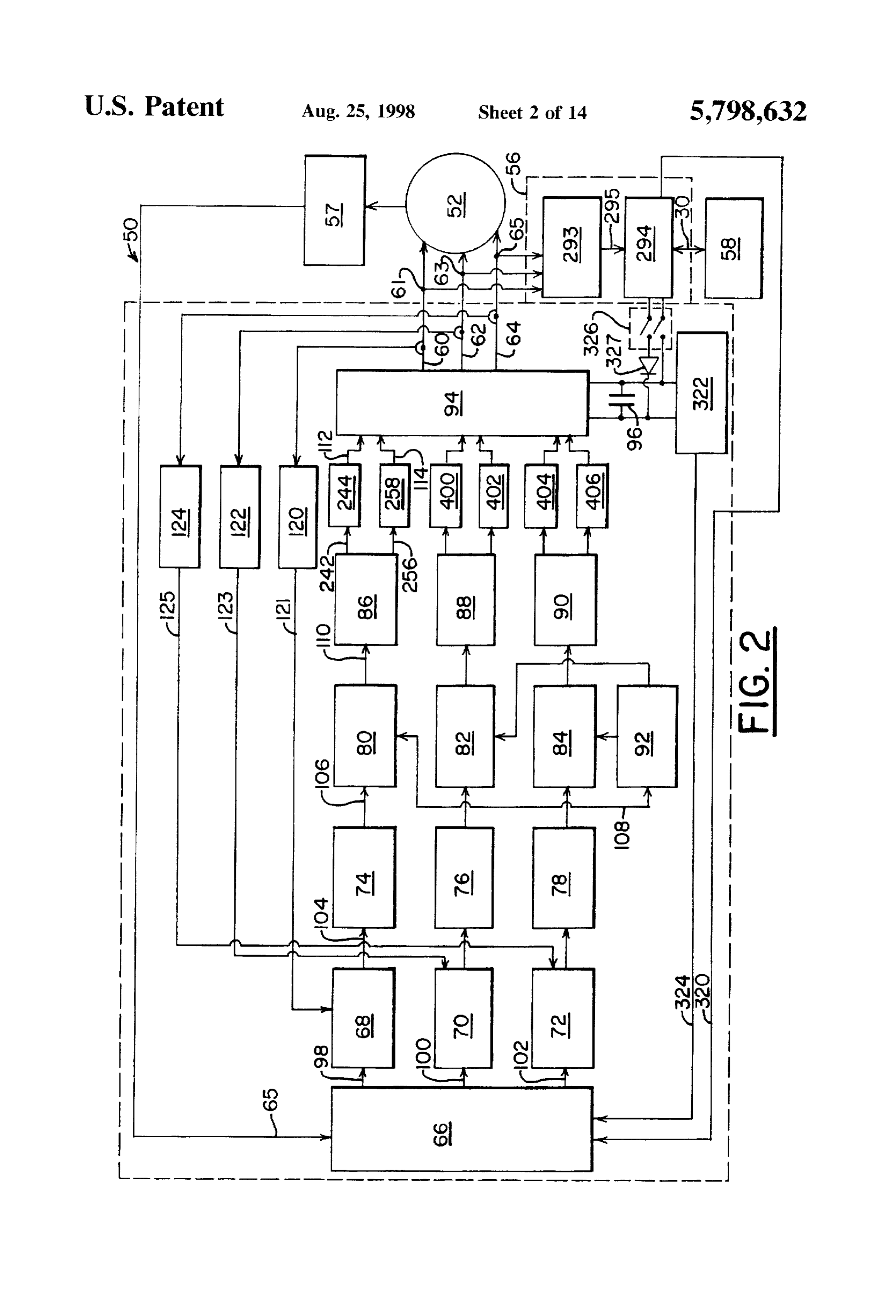
signals to the stator windings in the generator and the second FIG. 3 shows a comparison of the input voltage signal to current component being the current signal necessary to and the output voltage signals from the lock out circuit deliver the real electric power generated by the generator to portion of the generator system according to the present a utility at single-phase, unity power factor, and at sixty (60) 15 invention shown in FIG. 1;
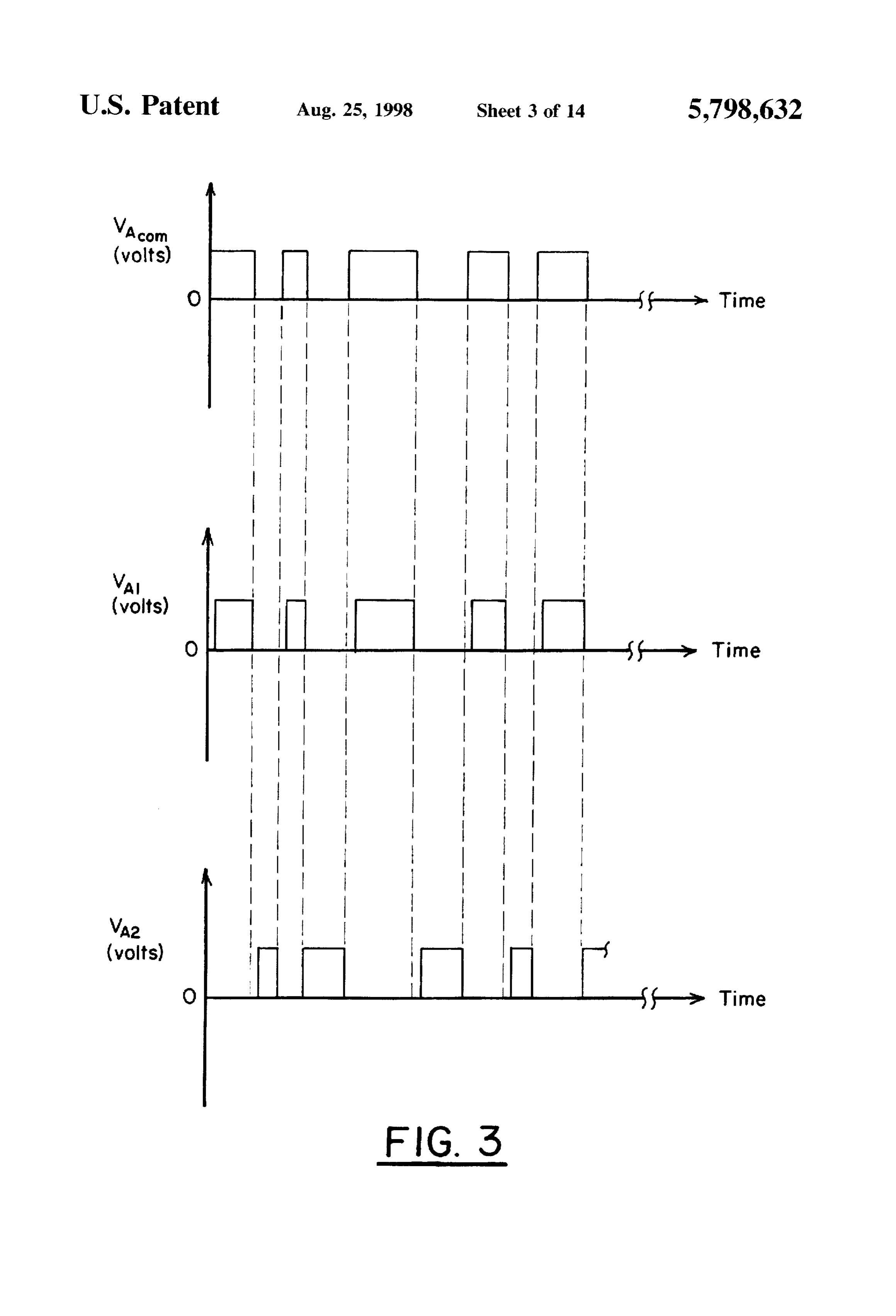
hertz, and a zero sequence filter or bandpass filter to allow the second current component to be delivered to the utility theFIG. lock 4 shows a comparison of the input voltage signal to out circuit and some of the voltage signals created while preventing the first current component from being in the lock out circuit of the generator system according to delivered to the utility. The first current component signals supplied by the excitation controller and supplied to the the present invention shown in FIG. 1;
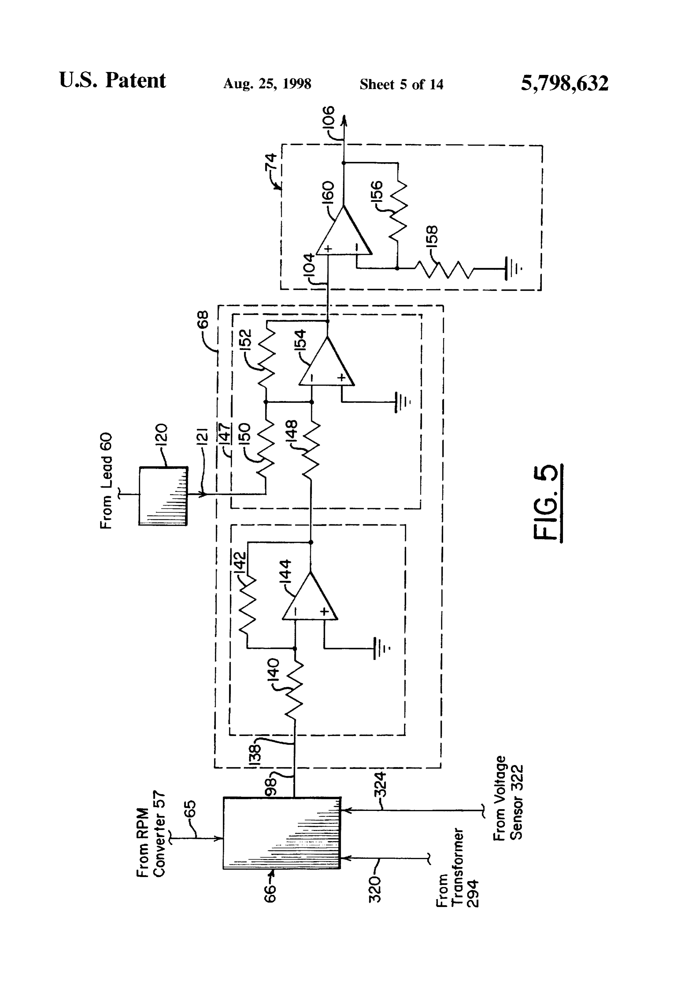
stator windings in the generator have a frequency that is 20 FIG. 5 shows a schematic diagram of the error detector continuously adjusted by the excitation controller so that an and the amplifier portions of the electronic circuitry of the optimum amount of power is continuously generated by the generator system of FIG. 1 constructed to create a signal generator during varying wind velocity conditions. The representing the difference between the signals generated by second signal components supplied by the excitation con the command current generator and the signals generated by troller and delivered to the zero sequence filter or bandpass 25 the power converter;
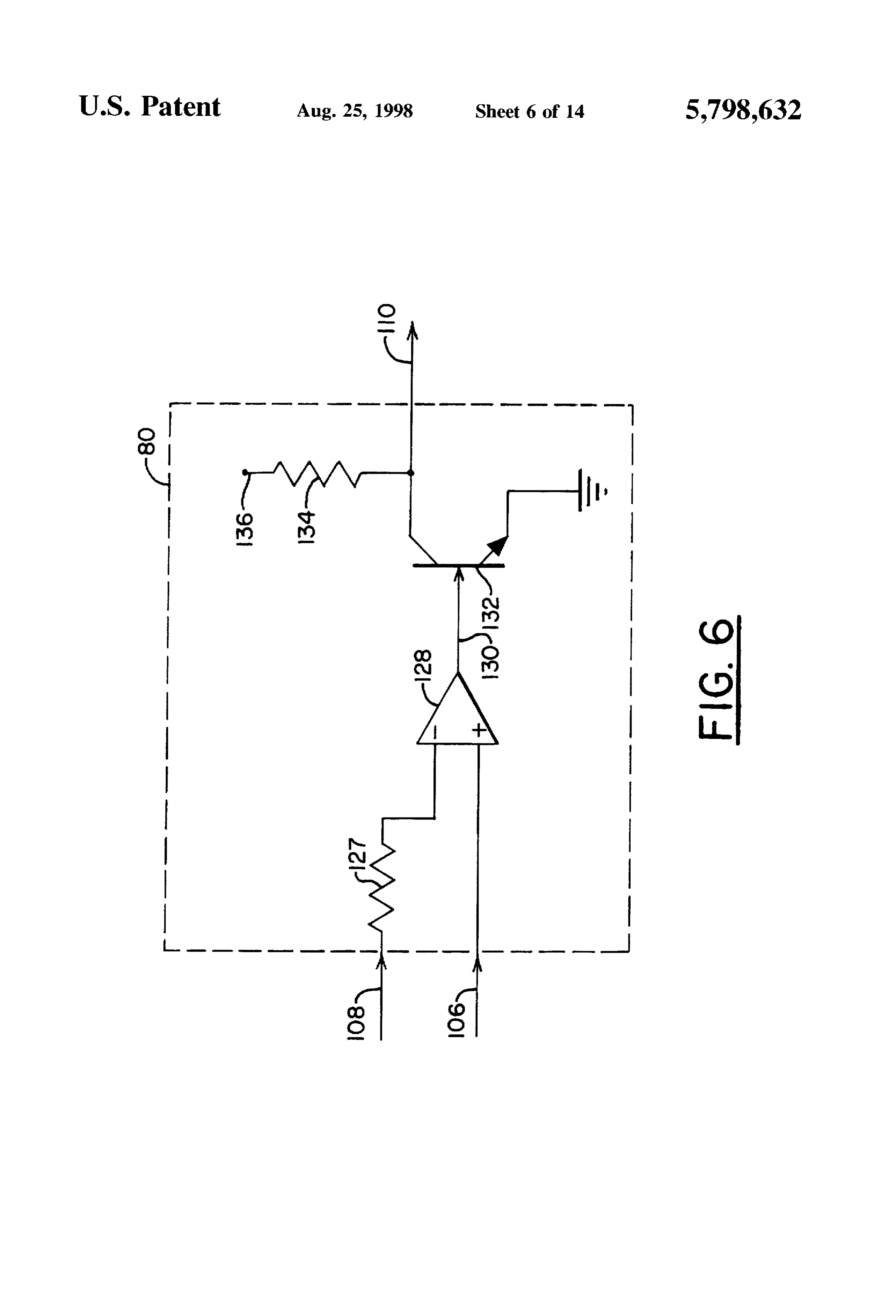
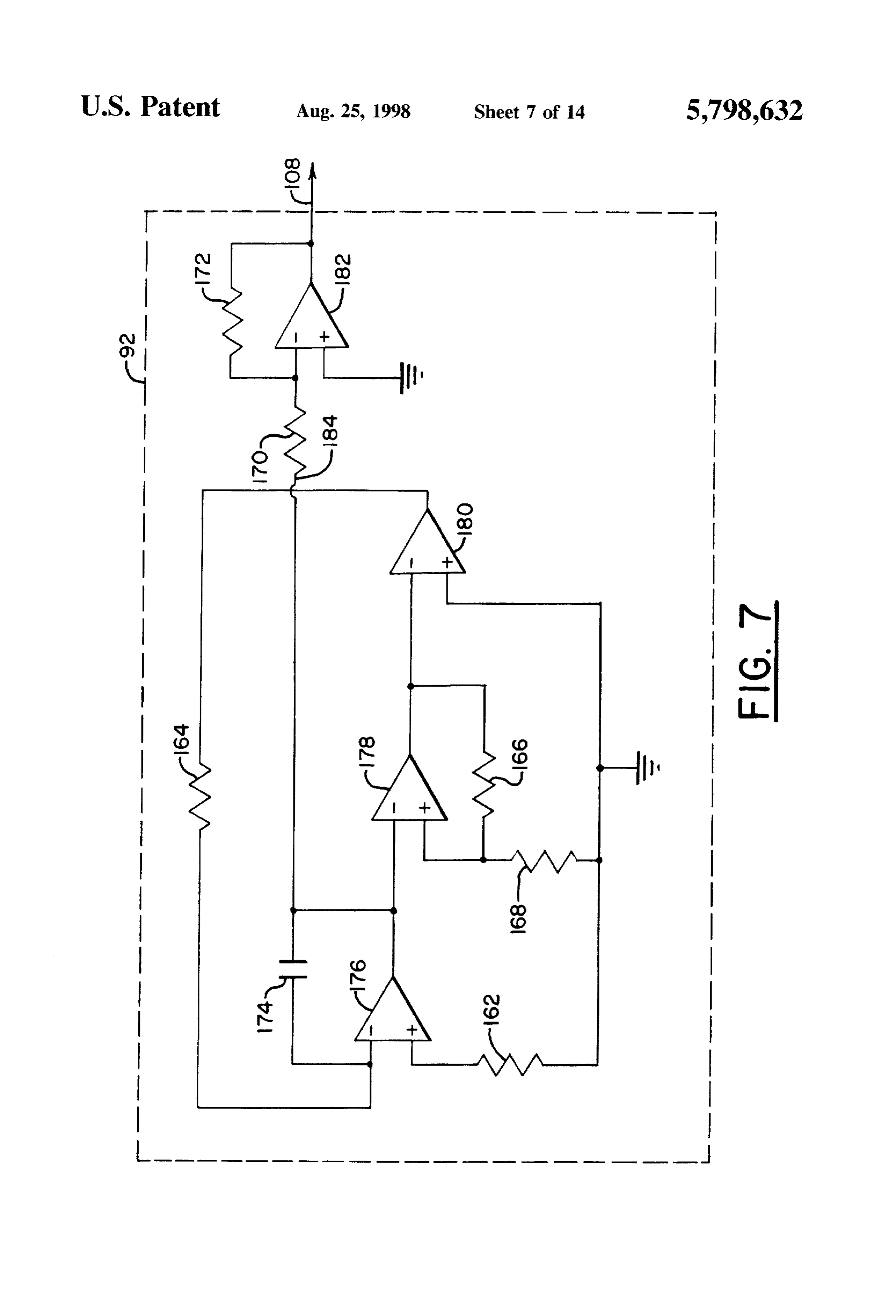
filter are in phase with the signals in the utility and have a FIG. 6 shows a schematic diagram of the comparator magnitude that is continuously adjusted by the excitation portion of the electronic circuitry of the generator system of controller so that all of the real power generated by the FIG. 1 constructed to compare the output of the amplifier generator is delivered to the utility. with the output of the triangle wave generator; The excitation controller includes an energy storage device that is charged when the power generator system is FIG. 7 shows a schematic diagram of the triangle wave activated. The excitation controller further includes power generator portion of the electronic circuitry of the generator switches, which can be comprised of transistors and diodes, system of FIG. 1 constructed to provide a triangle waveform that are individually and selectively activated and deacti voltage signal to the comparator;
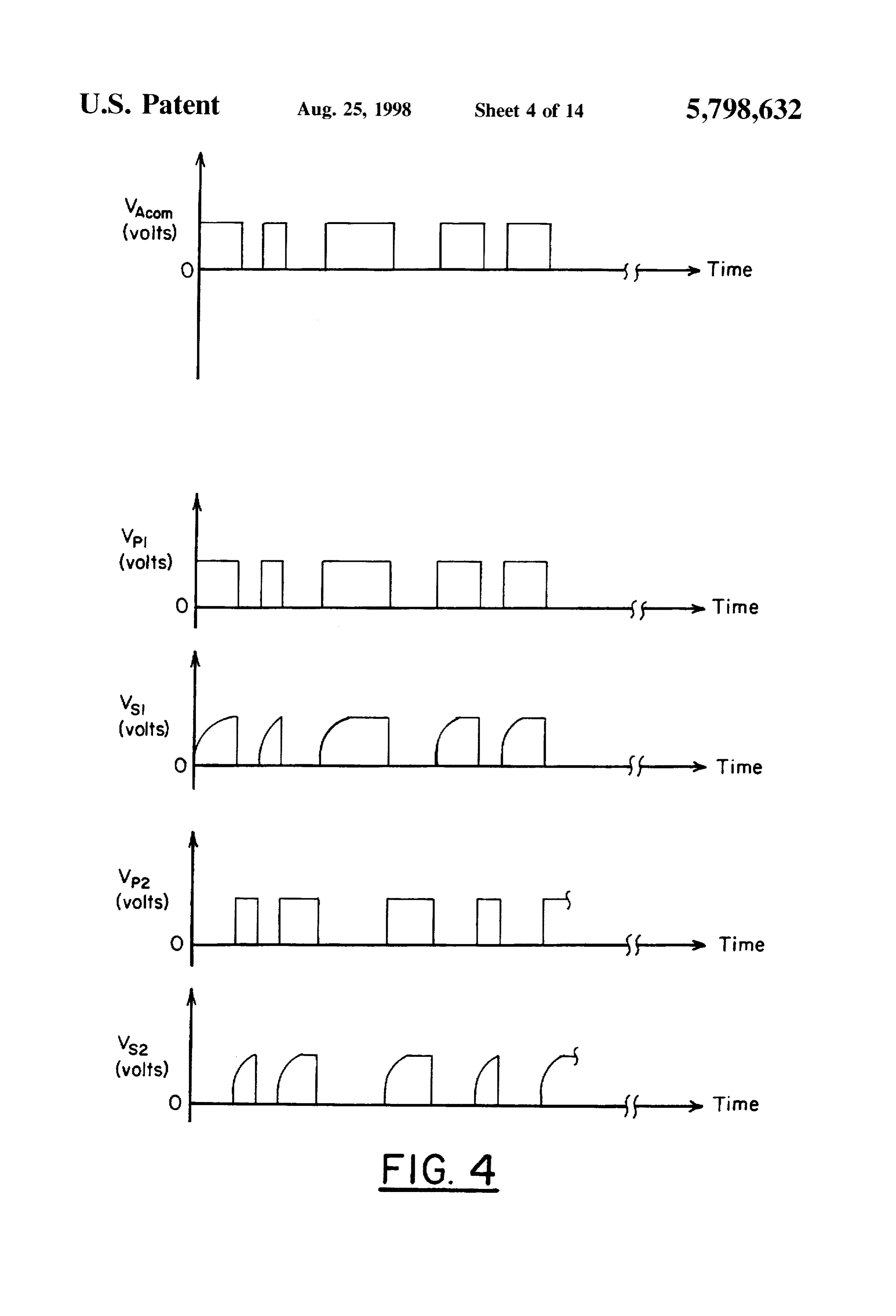
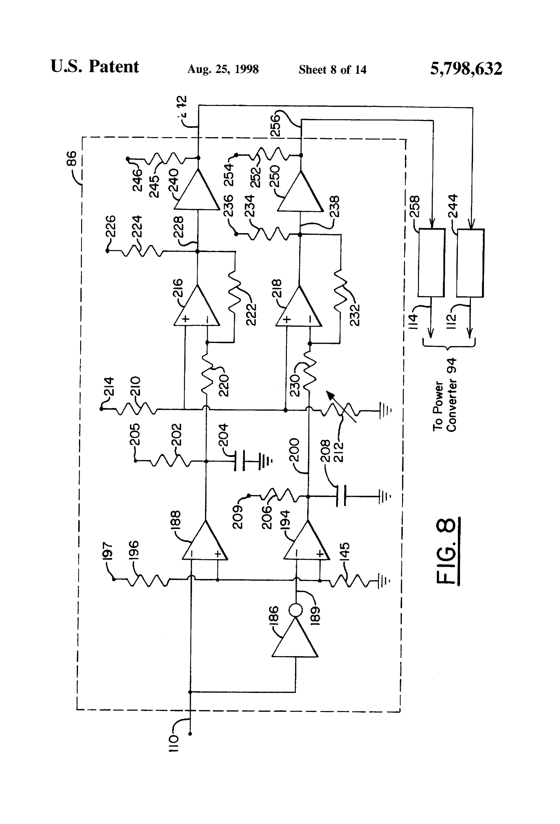
wated by pulsed voltage signals to create the desired current 35 FIG. 8 shows a schematic diagram of the lock out circuit signals. The frequency of the activation and the deactivation portion of the electronic circuitry of the generator system of of the power switches can be optionally controlled to FIG. 1 constructed to provide two pulse voltage signals to increase the useful life of the power switches. The current the power converter;
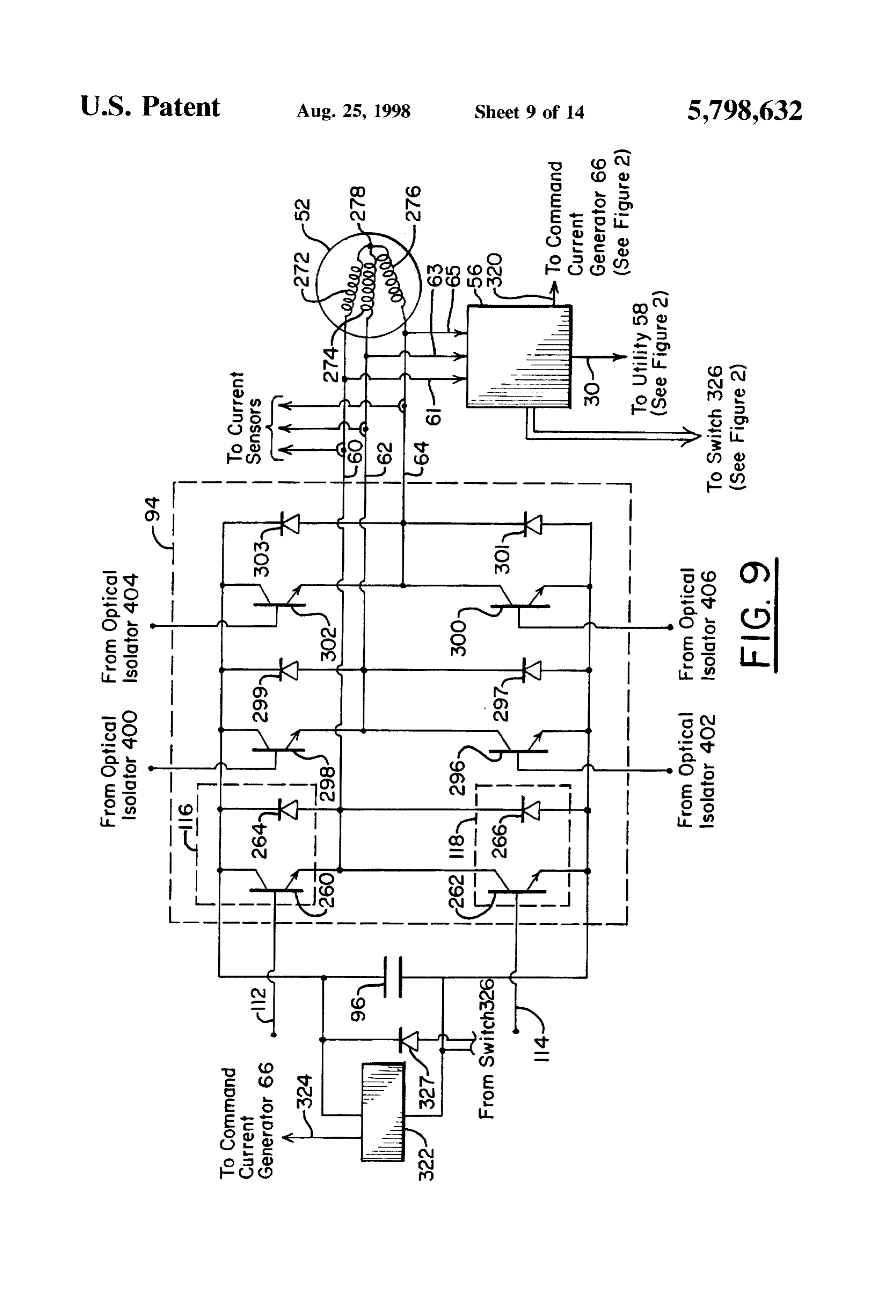
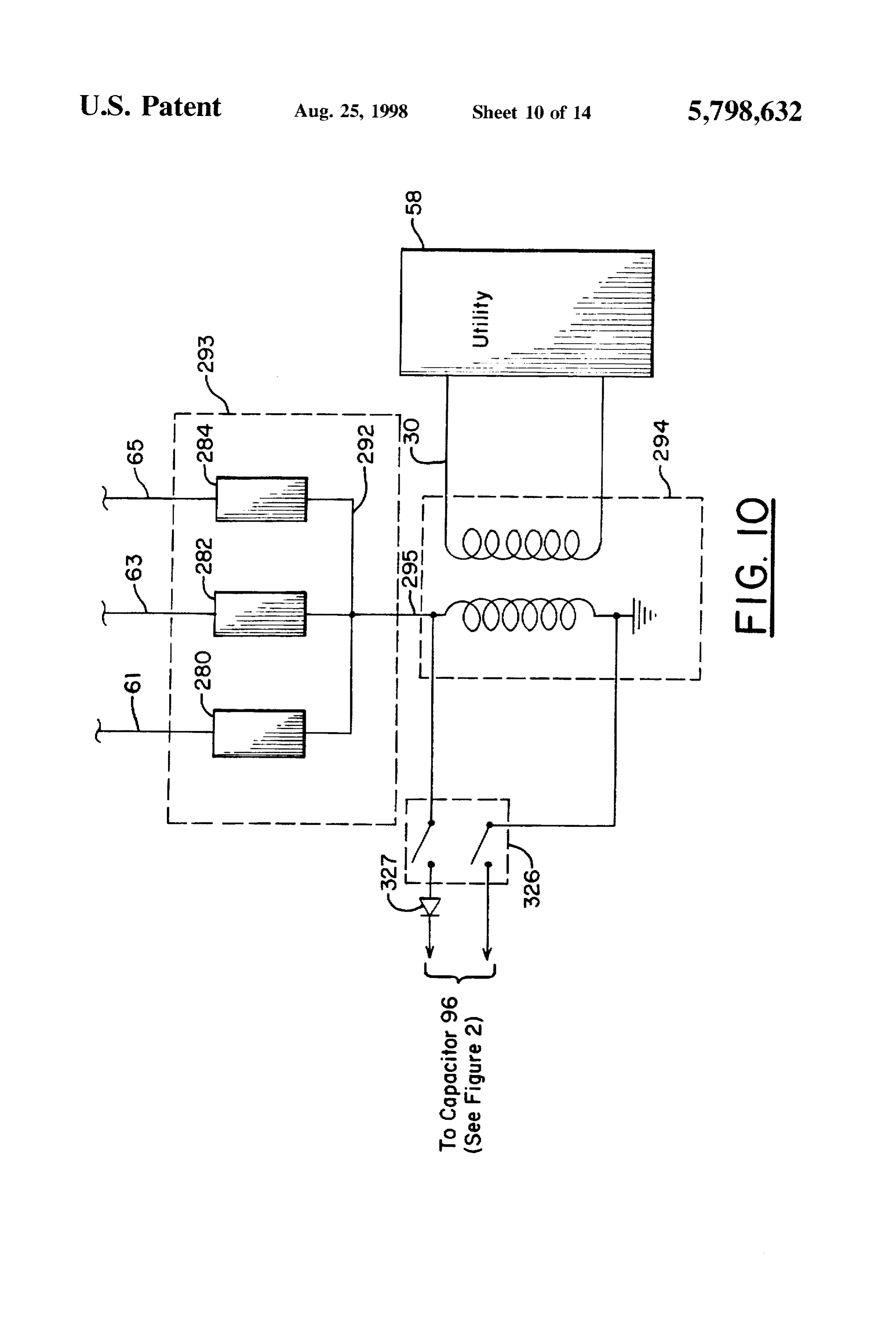
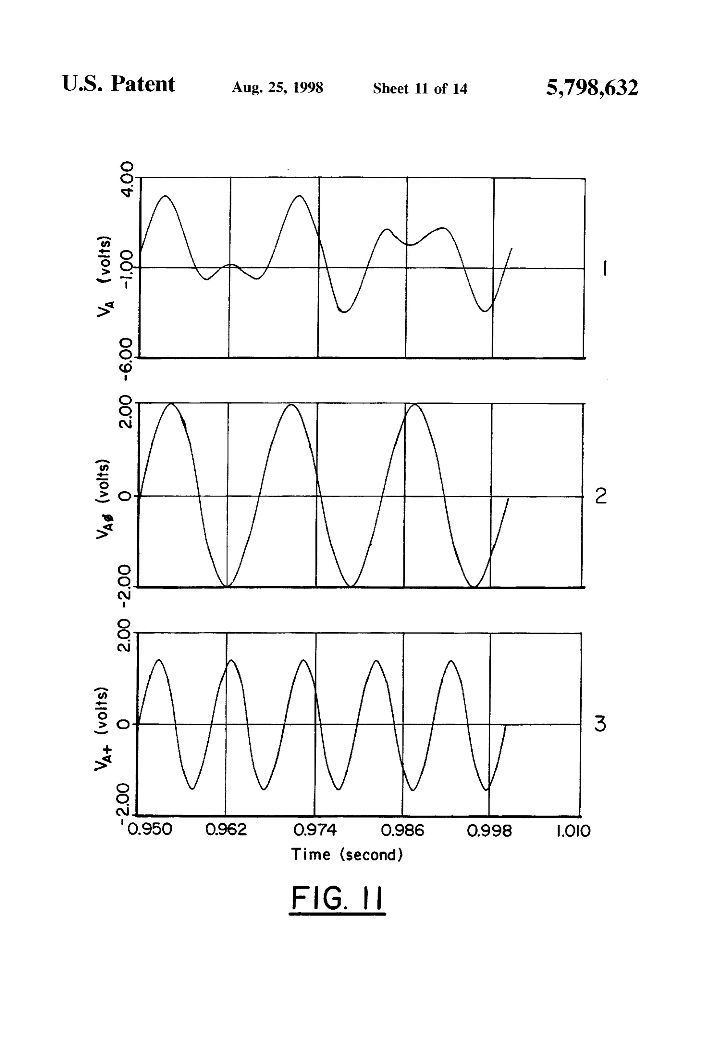
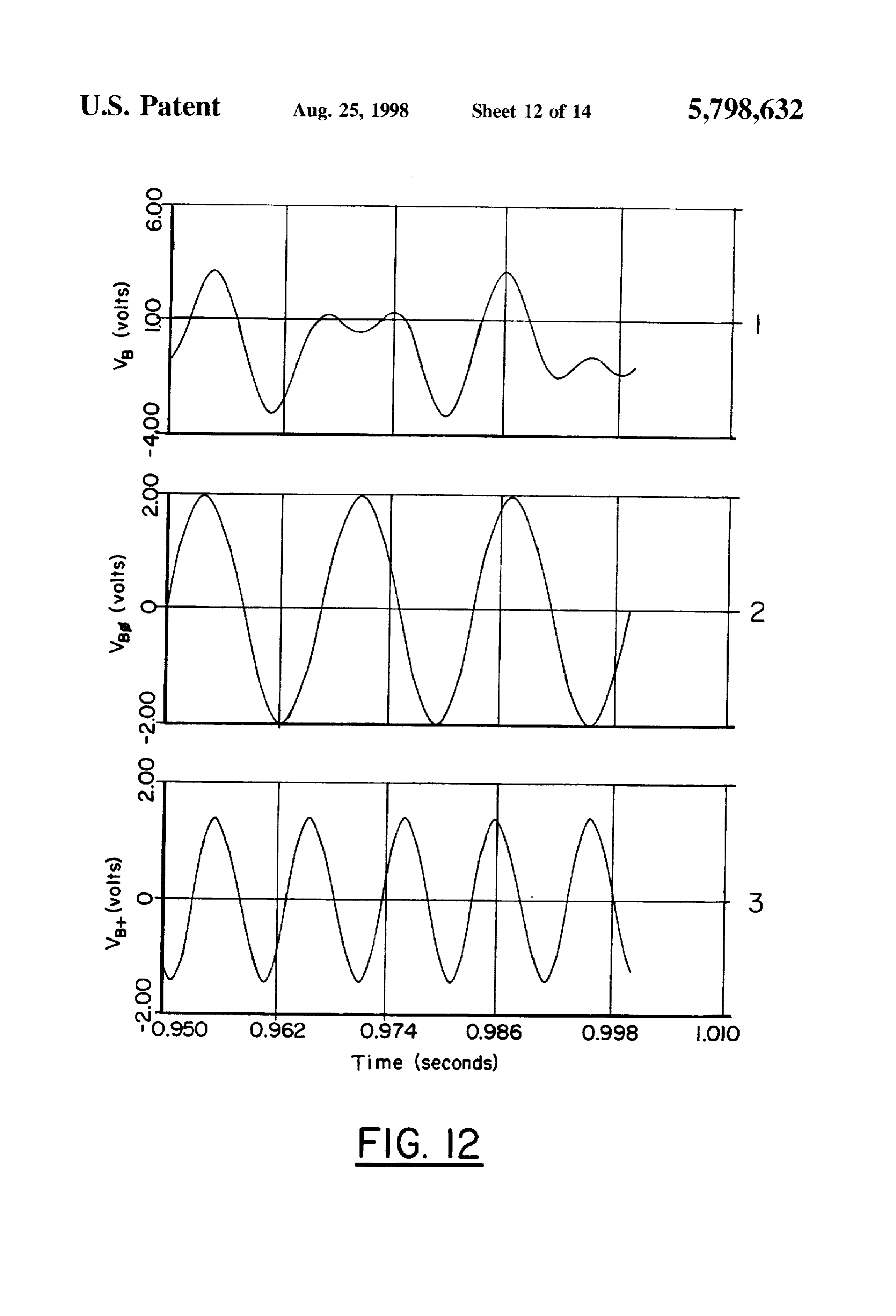
signals produced by the power switches continuously depletes the energy stored in the energy storage device. FIG. 9 shows a schematic diagram of the power converter However, the generated power continuously recharges the portion of the electronic circuitry of the generator system of energy in the energy storage system so that the average FIG. 1 constructed to use the voltage signals provided by the energy in the energy storage remains constant. A feedback lock out circuit to create the desired output current signals; loop is used to ensure that the first current component signals FIG. 10 shows a schematic diagram of the zero sequence are three-phase, balanced, and have the frequency required filter and transformer portions of the electronic circuitry of to maximize the generated power for the particular wind 45 the generator system of FIG. 1 constructed to provide single velocity. Feedback loops are also used to ensure that the phase electric power to the utility at sixty (60) hertz or other second current component signals have the magnitude nec standard frequency and at unity power factor; essary to deliver all of the generated power to the utility, to FIG. 11 shows an example voltage signal generated by the ensure that there is no excess build up of energy in the command current generator of the generator system of FIG. energy storage device, and to ensure that the frequency of 1;
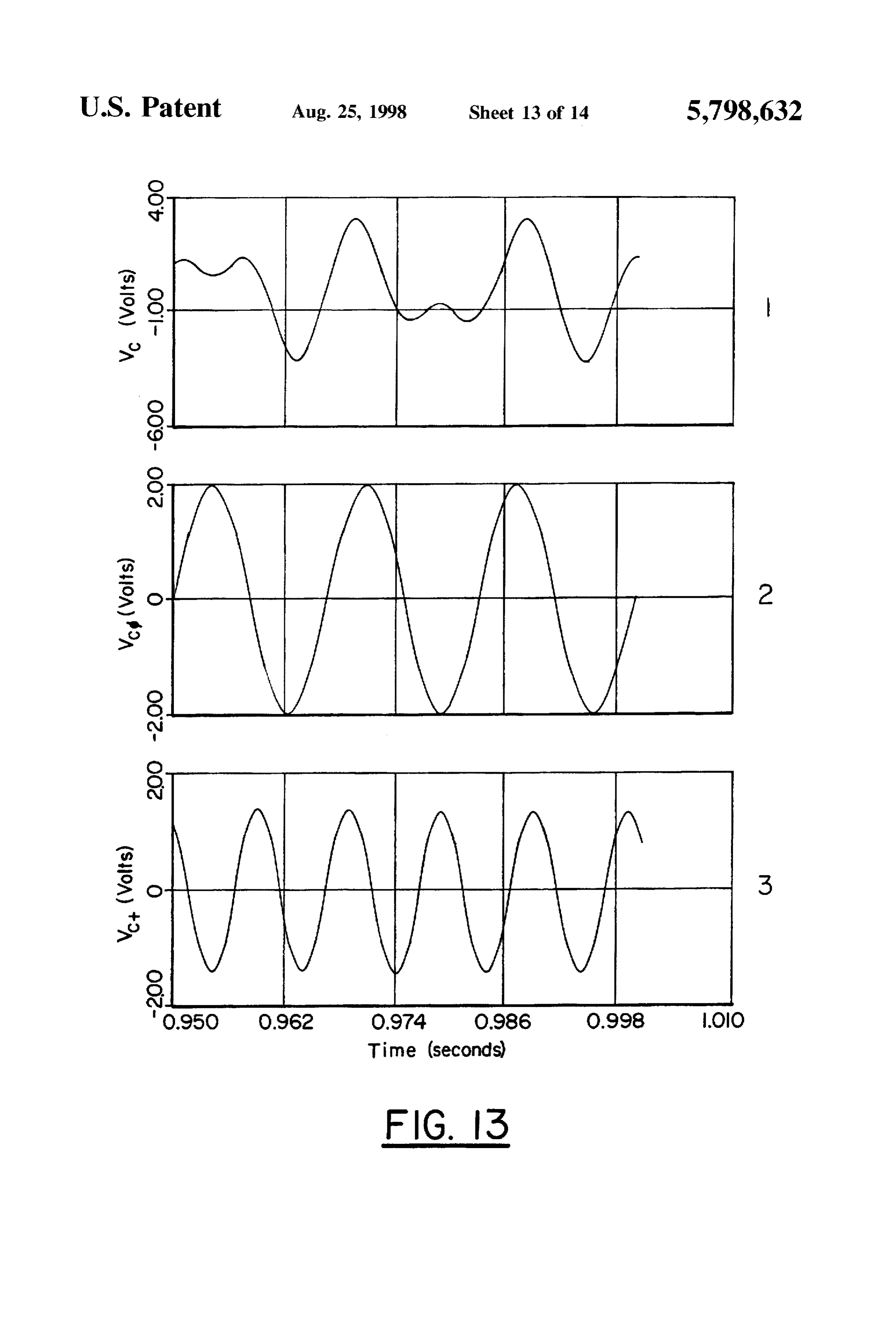
the second current component signals are all in phase with FIG. 12 shows another example voltage signal generated the signals in the utility by the command current generator of the generator system The excitation controller also includes a voltage signal of FIG. 1;
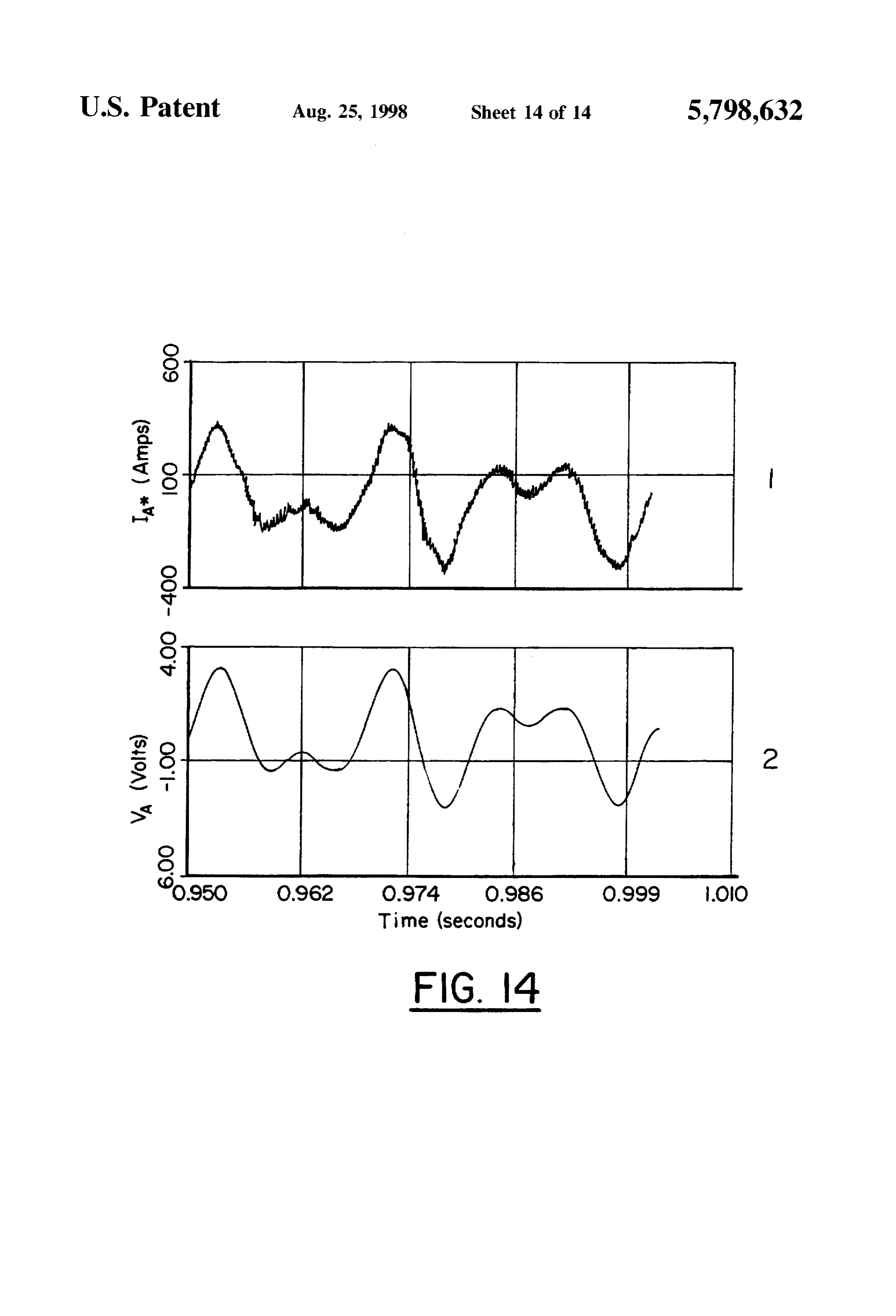
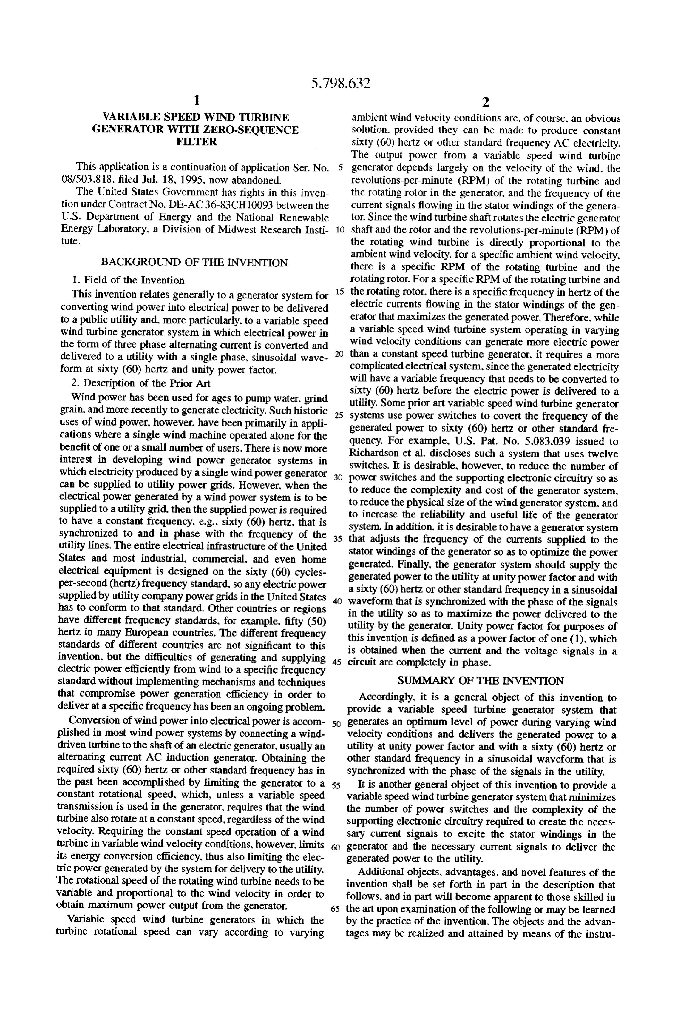
generator that creates specific voltage reference signals 55 FIG. 13 shows another example voltage signal generated based on the wind velocity, the phase of the signals in the by the command current generator of the generator system utility, and the amount of generated power that is delivered to the utility. The voltage reference signals created by the of FIG. FIG. 1; and 14 shows an example voltage signal generated by the voltage signal generator are compared to second voltage command current generator and the corresponding current signals that are representative of the current signals being signal generated by the power converter of the generator produced by the excitation controller. The resultant voltage system of FIG. 1.
signal is used as a template to create the pulsed voltage signals that control the activation and the deactivation of the DETALED DESCRIPTION OF THE power switches. PREFERRED EMBODIMENTS BRIEF DESCRIPTION OF THE DRAWINGS 65 The generator system 50 of this invention, as illustrated in The accompanying drawings, which are incorporated in the function block diagram of FIG. 1, includes a wind and form a part of the specifications, illustrate the preferred turbine AC generator 52 for converting wind power to
Page 18
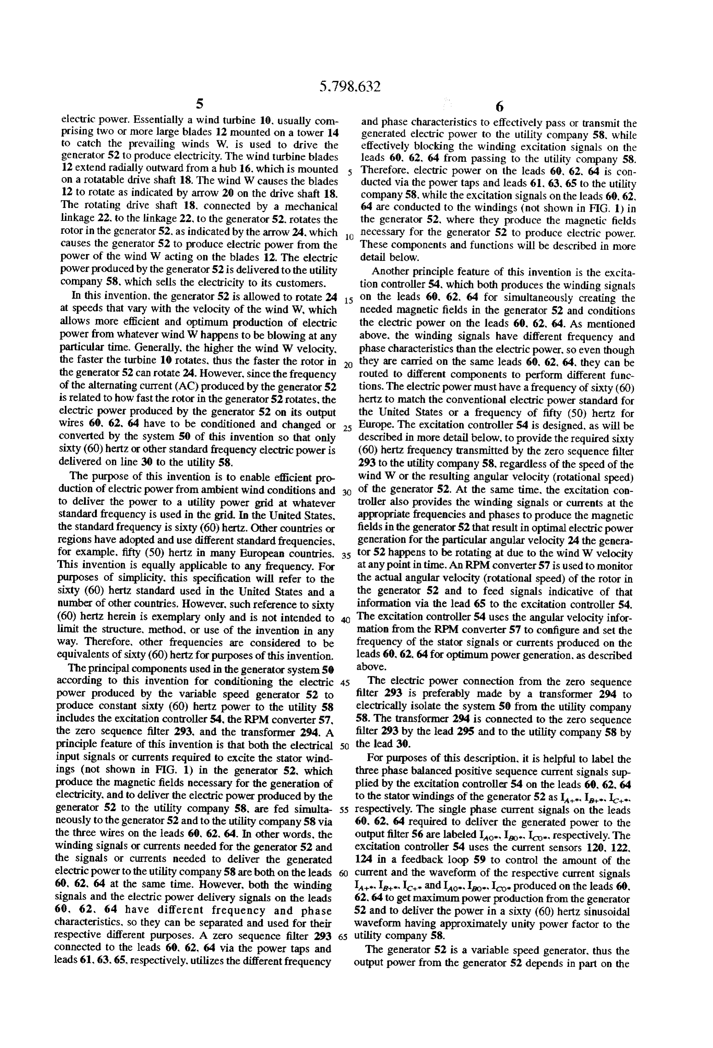
S 6 electric power. Essentially a wind turbine 10, usually com and phase characteristics to effectively pass or transmit the prising two or more large blades 12 mounted on a tower 14 generated electric power to the utility company 58, while to catch the prevailing winds W. is used to drive the effectively blocking the winding excitation signals on the generator 52 to produce electricity. The wind turbine blades leads 60, 62. 64 from passing to the utility company 58. 12 extend radially outward from a hub 16, which is mounted Therefore, electric power on the leads 60, 62. 64 is con on a rotatable drive shaft 18. The wind W causes the blades ducted via the power taps and leads 61, 63, 65 to the utility 12 to rotate as indicated by arrow 20 on the drive shaft 18. company 58, while the excitation signals on the leads 60.62. The rotating drive shaft 18, connected by a mechanical 64 are conducted to the windings (not shown in FIG. 1) in linkage 22, to the linkage 22, to the generator 52, rotates the the generator 52, where they produce the magnetic fields rotor in the generator 52, as indicated by the arrow 24, which 10 necessary for the generator 52 to produce electric power. causes the generator 52 to produce electric power from the These components and functions will be described in more power of the wind W acting on the blades 12. The electric detail below.
power produced by the generator 52 is delivered to the utility Another principle feature of this invention is the excita company 58, which sells the electricity to its customers. tion controller 54, which both produces the winding signals In this invention, the generator 52 is allowed to rotate 24 15 on the leads 60, 62. 64 for simultaneously creating the at speeds that vary with the velocity of the wind W, which needed magnetic fields in the generator 52 and conditions allows more efficient and optimum production of electric the electric power on the leads 60. 62, 64. As mentioned power from whatever wind Whappens to be blowing at any above, the winding signals have different frequency and particular time. Generally, the higher the wind Wvelocity. phase characteristics than the electric power, so even though the faster the turbine 10 rotates, thus the faster the rotor in 20 they are carried on the same leads 60, 62. 64, they can be the generator 52 can rotate 24. However, since the frequency routed to different components to perform different func of the alternating current (AC) produced by the generator 52 tions. The electric power must have a frequency of sixty (60) is related to how fast the rotor in the generator 52 rotates, the hertz to match the conventional electric power standard for electric power produced by the generator 52 on its output the United States or a frequency of fifty (50) hertz for wires 60. 62, 64 have to be conditioned and changed or 25 Europe. The excitation controller 54 is designed, as will be converted by the system 50 of this invention so that only described in more detail below, to provide the required sixty sixty (60) hertz or other standard frequency electric power is (60) hertz frequency transmitted by the zero sequence filter delivered on line 30 to the utility 58. 293 to the utility company 58, regardless of the speed of the The purpose of this invention is to enable efficient pro wind W or the resulting angular velocity (rotational speed) duction of electric power from ambient wind conditions and 30 of the generator 52. At the same time, the excitation con to deliver the power to a utility power grid at whatever troller also provides the winding signals or currents at the standard frequency is used in the grid. In the United States. appropriate frequencies and phases to produce the magnetic the standard frequency is sixty (60) hertz. Other countries or fields in the generator 52 that result in optimal electric power regions have adopted and use different standard frequencies, generation for the particular angular velocity 24 the genera for example, fifty (50) hertz in many European countries. 35 tor 52 happens to be rotating at due to the wind Wvelocity This invention is equally applicable to any frequency. For at any point in time. An RPM converter 57 is used to monitor purposes of simplicity, this specification will refer to the the actual angular velocity (rotational speed) of the rotor in sixty (60) hertz standard used in the United States and a the generator 52 and to feed signals indicative of that number of other countries. However, such reference to sixty information via the lead 65 to the excitation controller 54. (60) hertz herein is exemplary only and is not intended to The excitation controller 54 uses the angular velocity infor limit the structure, method, or use of the invention in any mation from the RPM converter 57 to configure and set the way. Therefore, other frequencies are considered to be frequency of the stator signals or currents produced on the equivalents of sixty (60) hertz for purposes of this invention. leads 60, 62. 64 for optimum power generation, as described The principal components used in the generator system 50 above.
according to this invention for conditioning the electric 45 The electric power connection from the zero sequence power produced by the variable speed generator 52 to filter 293 is preferably made by a transformer 294 to produce constant sixty (60) hertz power to the utility 58 electrically isolate the system 50 from the utility company includes the excitation controller 54, the RPM converter S7. 58. The transformer 294 is connected to the zero sequence the zero sequence filter 293, and the transformer 294. A filter 293 by the lead 295 and to the utility company 58 by principle feature of this invention is that both the electrical 50 the lead 30.
input signals or currents required to excite the stator wind For purposes of this description, it is helpful to label the ings (not shown in FIG. 1) in the generator 52, which three phase balanced positive sequence current signals sup produce the magnetic fields necessary for the generation of plied by the excitation controller 54 on the leads 60.62. 64 electricity, and to deliver the electric power produced by the to the stator windings of the generator 52 as Ia, I., I, generator 52 to the utility company 58, are fed simulta 55 respectively. The single phase current signals on the leads neously to the generator 52 and to the utility company 58 via 60. 62, 64 required to deliver the generated power to the the three wires on the leads 60, 62. 64. In other words, the output filter 56 are labeled Io., I, I., respectively. The winding signals or currents needed for the generator 52 and excitation controller 54 uses the current sensors 120, 122. the signals or currents needed to deliver the generated 124 in a feedback loop 59 to control the amount of the electric power to the utility company 58 are both on the leads current and the waveform of the respective current signals 60, 62. 64 at the same time. However, both the winding IA. I.e., lc and Iao, Ibo, Ico produced on the leads 60. signals and the electric power delivery signals on the leads 62, 64 to get maximum power production from the generator 60, 62. 64 have different frequency and phase 52 and to deliver the power in a sixty (60) hertz sinusoidal characteristics, so they can be separated and used for their waveform having approximately unity power factor to the respective different purposes. A zero sequence filter 293 65 utility company 58.
connected to the leads 60, 62. 64 via the power taps and The generator 52 is a variable speed generator, thus the leads 61, 63.65, respectively, utilizes the different frequency output power from the generator 52 depends in part on the
Page 19
velocity of the wind W, the rotational speed of the rotating Likewise, the actual current output signal I. from the rotor in the generator 52, and the frequency f. of the positive excitation controller 54 on the lead 64: Sequence current signals I. I. I.C. flowing in the stator ic-le-Hoo- (3) windings of the wind generator 52. The angular velocity or
RPM of the rotor in the generator 52 is related to the velocity The current output signals I. I. I. from the excitation of the wind W and the power load on the generator 52. controller 54 on the leads 60.62. 64. respectively, are also Generally, where there is a constant power load on the generator 52. thus fairly constant resistance to rotation of the used in a feedback loop 59 along with the current sensors rotor in the generator 52, the angular velocity of the wind controller 124
to create input voltage signals to the excitation on the leads 121, 123, 125. respectively. The turbine 10 and the generator 52 will vary in direct proportion voltage signals created
by the current sensors 120. 122, 124 to the velocity of the wind W. The frequency f, of the on the leads 121, 123, 125 are linearly related to the current positive Sequence current signals I.A., I, I.C. flowing in signals I. I. It flowing the stator windings of the generator 52 can be changed general terms, if the amplitude on of
the current signal I is too according to a specific relationship to the changing angular low, the feedback loop 59 causes the excitation velocity of the wind turbine 10 and the generator 52 so that 15 to increase the amplitude of the current signalcontroller I. If
the the output power of the generator 52 is maximized for a amplitude of the current signal I. is too high, the feedback particular wind W velocity. The leads 60, 62. 64 are con loop 59 causes the excitation controller 54 to decrease the nected to the stator windings in the generator 52, which is represented by the impedances 272.274. 276, respectively amplitude signals I of the current signal I. Likewise for the current and I. The excitation controller 54, the feed (see FIG. 9). The impedances 272, 274, 276 are primarily back loop 59, inductive and can be, for example, 2.706x10' henries, but output current the current sensors 120, 122, 124, and the signals I, I. I. from the excitation they may also include a small resistance of, for example, controller 54 on the leads 60, 62. 64, respectively, are 0.0085 ohms. The use of a variable speed generator to discussed in greater detail below.
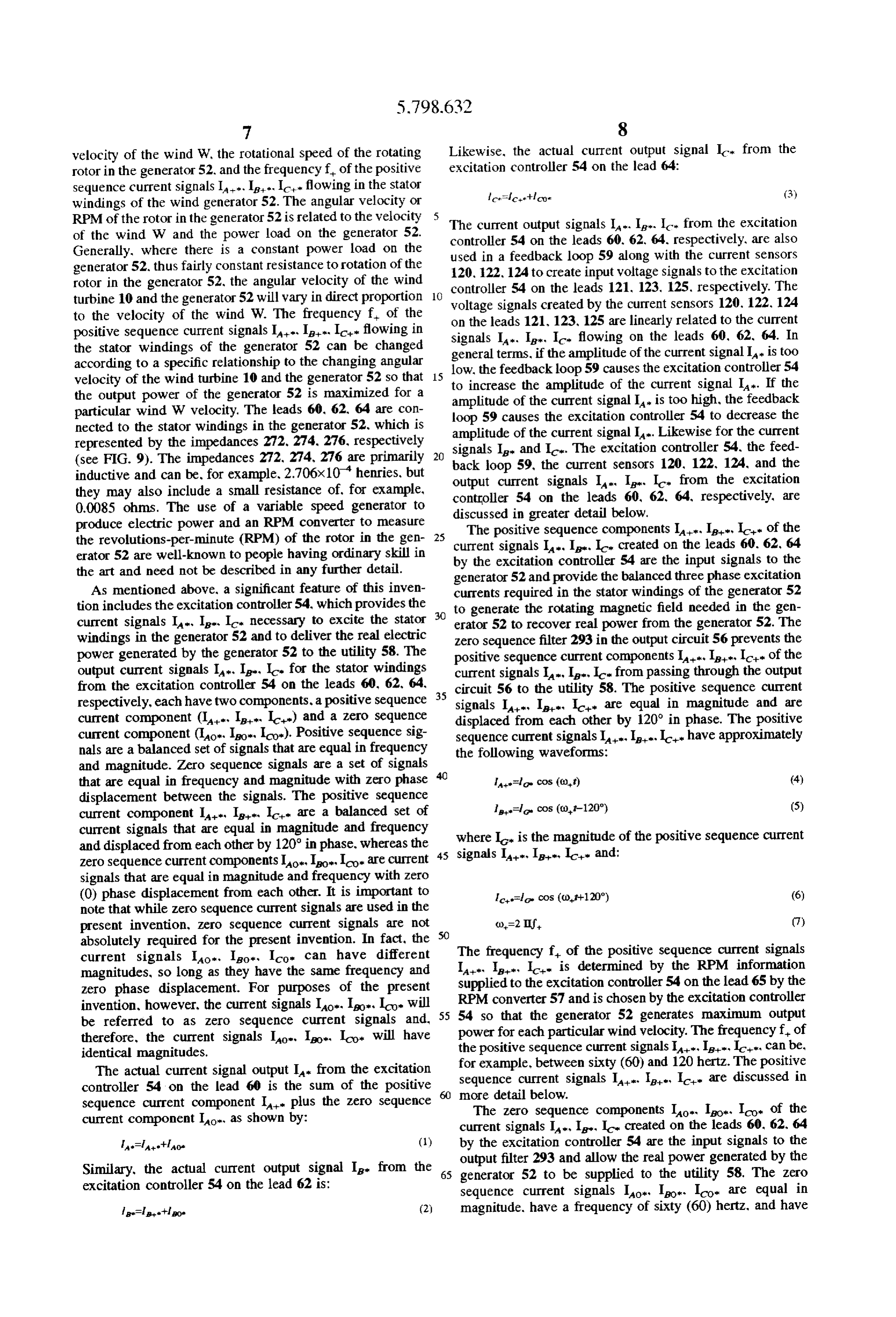
produce electric power and an RPM converter to measure The positive sequence components I, I., I of the the revolutions-per-minute (RPM) of the rotor in the gen 25 current signals I. I.. I created on the leads 60. 62, 64 erator 52 are well-known to people having ordinary skill in by the excitation controller 54 are the input signals to the the art and need not be described in any further detail. generator 52 and provide the balanced three phase excitation As mentioned above, a significant feature of this inven currents required in the stator windings of the generator 52 tion includes the excitation controller 54, which provides the 30 to generate the rotating magnetic field needed in the gen current signals I, I.. I necessary to excite the stator erator 52 to recover real power from the generator 52. The windings in the generator 52 and to deliver the real electric zero sequence filter 293 in the output circuit 56 prevents the power generated by the generator 52 to the utility 58. The positive sequence current components at I, Ic of the output current signals IA. I. I. for the stator windings current signals I, I., Ic. from passing through the output from the excitation controller 54 on the leads 60, 62. 64, circuit 56 to the utility 58. The positive sequence current respectively, each have two components, a positive sequence 35 signals Ia, Ie, Ic are equal in magnitude and are current component (IA. I. I.) and a zero sequence displaced from each other by 120° in phase. The positive current component (Io, Io, Ico). Positive sequence sig sequence current signals I.I.I. have approximately nals are a balanced set of signals that are equal in frequency the following waveforms:
and magnitude. Zero sequence signals are a set of signals that are equal in frequency and magnitude with zero phase larlo cos (a),t) (4) displacement between the signals. The positive sequence current component I., I, c. are a balanced set of le= cos (cof-120") (5) current signals that are equal in magnitude and frequency where I is the magnitude of the positive sequence current and displaced from each other by 120° in phase, whereas the 45 signals IA-, In, Ic- and:
Zero Sequence current components Io, Io. Ico are current signals that are equal in magnitude and frequency with zero (0) phase displacement from each other. It is important to c=l cos (cdf+120") (6) note that while zero sequence current signals are used in the present invention, Zero sequence current signals are not co=2 If (7) absolutely required for the present invention. In fact, the The frequency f, of the positive sequence current signals current signals Iao., Igo, Ico can have different magnitudes, so long as they have the same frequency and I., I, I. is determined by the RPM information Zero phase displacement. For purposes of the present supplied to the excitation controller 54 on the lead 65 by the invention, however, the current signals Io. Io. Ico will 55 RPM converter 57 and is chosen by the excitation controller 54 so that the generator 52 generates maximum output be referred to as zero sequence current signals and, powerfor therefore, the current signals Io, Io, Ico will have the positiveeach particular wind velocity. The frequency f. of sequence current signals I. I.e., I, can be, identical magnitudes.
The actual current signal output I from the excitation for example, between sixty (60) and 120 hertz. The positive controller 54 on the lead 60 is the sum of the positive Sequence current signals I. I. I.e. are discussed in sequence current component I. plus the Zero sequence more The detail below.
Zero Sequence components Io, Io. I of the current component Io, as shown by: current signals I. I. I. created on the leads 60, 62. 64 A-lastiao (1) by the excitation controller 54 are the input signals to the output filter 293 and allow the real power generated by the
Similary, the actual current output signal I. from the 65 generator 52 to be supplied to the utility 58. The zero excitation controller 54 on the lead 62 is: sequence current signals Io, Io. Ico are equal in le-leafleo (2) magnitude. have a frequency of sixty (60) hertz, and have
Page 20
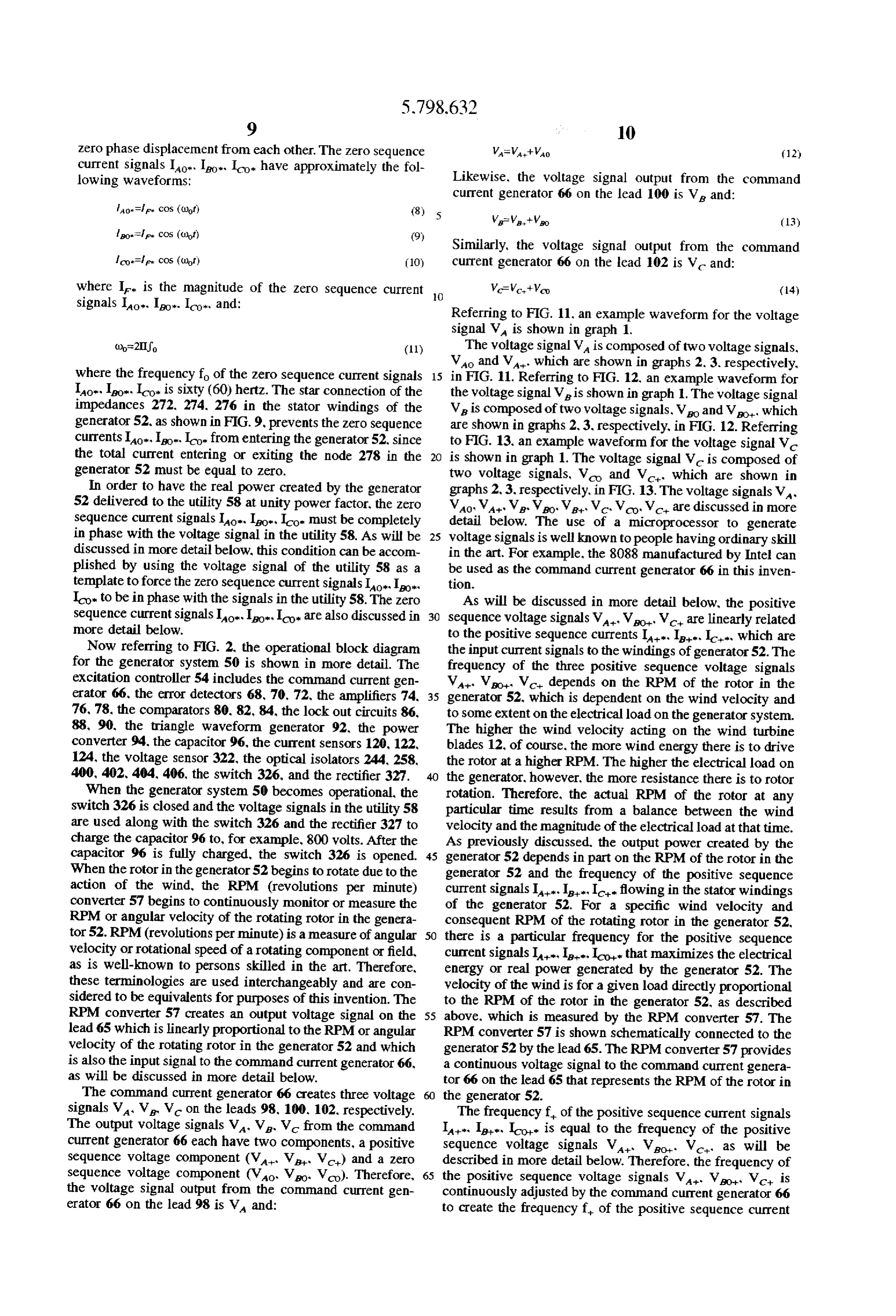
Zero phase displacement from each other. The zero sequence Was Watt-Vao (12) current Signals Io, Io, I have approximately the fol lowing waveforms: Likewise, the voltage signal output from the command current generator 66 on the lead 100 is V and:
lo. Fire cos (clof) (8) 5.
Similarly, the voltage signal output from the command
Ico-Fle cos (unor) (10) current generator 66 on the lead 102 is V and: where I is the magnitude of the Zero sequence current 10 signals Iao. Ito. Ico, and:
Referring to FIG. 11, an example waveform for the voltage signal Va is shown in graph 1.
(Dor-2IIJo (11) The voltage signal V is composed of two voltage signals, Vo and V. which are shown in graphs 2, 3, respectively, where the frequency fo of the zero sequence current signals 15 in FIG. 11. Referring to FIG. 12, an example waveform for Io., Io. Ico. is sixty (60) hertz. The star connection of the the voltage signal Vis shown in graph 1. The voltage signal impedances 272, 274. 276 in the stator windings of the V is composed of two voltage signals, Vo and Vol, which generator 52, as shown in FIG. 9, prevents the zero sequence are shown in graphs 2.3, respectively, in FIG. 12. Referring currents Io., Io, Ilo from entering the generator 52, since to FIG. 13, an example waveform for the voltage signal Vc the total current entering or exiting the node 278 in the is shown in graph 1. The voltage signal V is composed of generator 52 must be equal to zero. two voltage signals, V and V, which are shown in In order to have the real power created by the generator graphs 2, 3, respectively, in FIG. 13. The voltage signals VA. 52 delivered to the utility 58 at unity power factor, the zero Vao, VA.V. Vo V, Vc, Vco, Vc, are discussed in more Sequence current signals Io, Ito, Ico must be completely detail below. The use of a microprocessor to generate in phase with the voltage signal in the utility 58. As will be 25 voltage signals is well known to people having ordinary skill discussed in more detail below, this condition can be accom in the art. For example, the 8088 manufactured by Intel can plished by using the voltage signal of the utility 58 as a be used as the command current generator 66 in this inven template to force the Zero sequence current signals Io., I, tion.
Ico. to be in phase with the signals in the utility 58. The zero As will be discussed in more detail below, the positive Sequence current signals Io, Io, Ico are also discussed in 30 sequence voltage signals V. Vo V are linearly related more detail below. to the positive sequence currents I. I., I, which are Now referring to FIG. 2, the operational block diagram the input current signals to the windings of generator 52. The for the generator system 50 is shown in more detail. The frequency of the three positive sequence voltage signals excitation controller 54 includes the command current gen V. V. V. depends on the RPM of the rotor in the erator 66, the error detectors 68, 70, 72, the amplifiers 74, 35 generator 52, which is dependent on the wind velocity and 76, 78, the comparators 80. 82, 84, the lock out circuits 86, to some extent on the electrical load on the generator system. 88, 90, the triangle waveform generator 92, the power The higher the wind velocity acting on the wind turbine converter 94, the capacitor 96, the current sensors 120, 122, blades 12, of course, the more wind energy there is to drive 124, the voltage sensor 322, the optical isolators 244, 258, the rotor at a higher RPM. The higher the electrical load on 400, 402,404, 406, the switch 326, and the rectifier 327. the generator, however, the more resistance there is to rotor When the generator system 50 becomes operational, the rotation. Therefore, the actual RPM of the rotor at any switch 326 is closed and the voltage signals in the utility 58 particular time results from a balance between the wind are used along with the switch 326 and the rectifier 327 to velocity and the magnitude of the electrical load at that time. charge the capacitor 96 to, for example, 800 volts. After the As previously discussed, the output power created by the capacitor 96 is fully charged, the switch 326 is opened. 45 generator 52 depends in part on the RPM of the rotor in the When the rotor in the generator 52 begins to rotate due to the generator 52 and the frequency of the positive sequence action of the wind, the RPM (revolutions per minute) current signals I. I. It flowing in the stator windings converter 57 begins to continuously monitor or measure the of the generator 52. For a specific wind velocity and RPM or angular velocity of the rotating rotor in the genera consequent RPM of the rotating rotor in the generator 52, tor 52. RPM (revolutions perminute) is a measure of angular 50 there is a particular frequency for the positive sequence velocity or rotational speed of a rotating component or field, current signals I, I. Ico that maximizes the electrical as is well-known to persons skilled in the art. Therefore, energy or real power generated by the generator 52. The these terminologies are used interchangeably and are con velocity of the wind is for a given load directly proportional sidered to be equivalents for purposes of this invention. The to the RPM of the rotor in the generator 52, as described RPM converter 57 creates an output voltage signal on the 55 above, which is measured by the RPM converter 57. The lead 65 which is linearly proportional to the RPM or angular RPM converter 57 is shown schematically connected to the velocity of the rotating rotor in the generator 52 and which generator 52 by the lead 65. The RPM converter 57 provides is also the input signal to the command current generator 66, a continuous voltage signal to the command current genera as will be discussed in more detail below. tor 66 on the lead 65 that represents the RPM of the rotor in The command current generator 66 creates three voltage the generator 52.
signals V, V V on the leads 98, 100. 102, respectively. The frequency f. of the positive sequence current signals The output voltage signals V, V, V from the command I. I.e., Ico is equal to the frequency of the positive current generator 66 each have two components, a positive sequence voltage signals V, Vol. V, as will be Sequence voltage component (Val V, V) and a Zero described in more detail below. Therefore, the frequency of sequence voltage component (Vo Vo Vo). Therefore, 65 the positive sequence voltage signals Val Vo Vc is the voltage signal output from the command current gen continuously adjusted by the command current generator 66 erator 66 on the lead 98 is V and: to create the frequency f, of the positive sequence current
Page 21
signals I. I. I. that maximizes the real power creates a corresponding voltage signal V. on the lead 121. generated by the generator 52 at the varying wind velocities, Likewise, the current sensor 122 senses the current signal The information relating the RPM of the rotor in the I. produced on the lead 62 by the power converter 94 and generator 52 to optimal frequency F, is stored in the creates a corresponding voltage signal V. on the lead 123. command current generator 66 in, for example, a look-up and the current sensor 124 senses the current signal I, table. The optimal frequency F can also be computed from produced on the lead 64 by the power converter 94 and an equation or a set of equations that are stored in the creates a corresponding voltage signal V. on the lead 125. command current generator 52 where the optimal frequency The current sensors 120. 122, 124 do not disturb or change is a function of the RPM of the rotor in the generator 52. The the current signals I. I. I. on the leads 60, 62, 64. relationship between the RPM of the rotor in the generator Current sensors and the use of current sensors are well 52 and the optimal frequency F can be computed by known to people having ordinary skill in the art and need not equations or determined empirically and can also be differ be described in any further detail. ent for different types of generators. The positive sequence The output voltage signal VA. from the current sensor 120 voltage signals V. Vo V generated by the command on the lead 121 is an input signal to the error detector 68. current generator 66 are equal in magnitude. are displaced 5 Likewise, the output voltage signal V. from the current from each other by 120° in phase. and have the following sensor 122 on the lead 123 is an input signal to the error waveforms: detector 70 and the output voltage signal V from the current sensor 124 on the lead 125 is an input signal to the
W=V cos (c.), t) (15) error detector 72.
The signal processing of the voltage signals V.V. in the error detector 68, the amplifier 74, the comparator 80, the
V-W cos (cott-120) (17) lockout circuit 86, and the optical isolators 244, 258 is identical to the signal processing of the voltage signals V where V is the magnitude of the positive sequence voltage V. in the error detector 70, the amplifier 76, the comparator signals V. V. V. The (), in the equations 15-17 is the 25 82, the lockout circuit 88, and the optical isolators 400, 402. same as the (), in the equations 4-6. which are both identical to the signal processing of the As will be discussed in more detail below, the zero voltage signals V. V. in the error detector 72, the sequence voltages Vo Vo Vo are linearly related to the amplifier 78, the comparator 84, the lockout circuit 90, and Zero sequence current signals Io, I., I, which are the the optical isolators 404, 406. Therefore, only the signal input current signals to the output filter 56 that allow the 30 processing for the voltage signals V and V. is discussed generated power to be delivered to the utility 58. The zero in further detail.
sequence voltage signals Vo Vo Vo are equal in The error detector 68 determines the difference between magnitude, have a frequency of sixty (60) hertz, have Zero the voltage signal V created by the command current phase displacement from each other, and have the following generator 66 on the lead 98 and the voltage signal V. waveforms: 35 created by the current sensor 120 on the lead 121. The Vo-V cos (alot) (18) difference between the two voltage signals V. V. is the error voltage signal V which is also the output signal
WotWr cos (c)of) (19) from the error detector 68 on the lead 104 and the input
signal to the amplifier 74. The amplifier 74 amplifies the voltage signal V to strengthen it and provide a stronger where V is the magnitude of the zero sequence voltage input signal to the comparator 80. The output voltage signal signals Vo Vo Vo. The () in the equations 18-20 is also VA. from the amplifier 74 on the lead 106 is an input the same as the () in the equations 8-10. As previously voltage signal to the comparator 80. The error detector 68 discussed, the Zero Sequence current signals Lao. Io. Ico and the amplifier 74 are discussed in more detail below. must be completely in phase with the voltage signal in the 45 The comparator 80 continuously compares the input volt utility 58 so that the power supplied to the utility has a unity age signal VA on the lead 106 with the input voltage power factor. This objective can be accomplished by using signal V on the lead 108. The voltage signal W on the the voltage signal of the utility 58 as a template to force the lead 108 is the output signal from the triangle waveform Zero Sequence current signals Io, Io. Ico to be in phase generator 92. The voltage signal V has a triangular with the voltage signal in the utility 58. More specifically, 50 waveform and a frequency of, for example, 5,000 hertz. If the transformer 294 creates a voltage signal on the lead 320 the instantaneous amplitude of the voltage signal Va is that is in phase with the voltage signal in the utility 58. The greater than the instantaneous amplitude of the voltage command current generator 66 creates the zero sequence signal Vaa, the output voltage signal Van from the voltage signals Vo Vo Vo on the leads 98, 100, 102. comparator 80 on the lead 110 is approximately a five (5) respectively, with the needed phase so that the Zero sequence 55 volt voltage signal. If the instantaneous amplitude of the current signals Io, Io. Ico from the power converter 94 on voltage signal V is less than the instantaneous amplitude the leads 60. 62, 64, respectively, are completely in phase of the voltage signal VA, the output voltage signal Van with the voltage signal in the utility 58. from the comparator 80 on the lead 110 is approximately a The output voltage signal VA from the command current Zero (0) voltage signal. Therefore, the output voltage signal generator 66 on the lead 98 is an input signal to the error V from the comparator 80 on the lead 110 is a nonperi detector 68. Likewise, the output voltage signal V from the odic pulsed signal where the duration of each pulse is command current generator 66 on the lead 100 is an input linearly related to the amount of time that the amplitude of signal to the error detector 70, and the output voltage signal the voltage signal V is greater than the amplitude of the V from the command current generator 66 on the lead 102 voltage signal VA and the duration between pulses is is an input signal to the error detector 72. 65 linearly related to the amount of time that the amplitude of The current sensor 120 senses the current signal I. the voltage signal V is less than the amplitude of the produced on the lead 60 by the power converter 94 and voltage signal Va. An example waveform for the voltage
Page 22
signal VA is shown in FIG. 3. The comparator 80 is 116, 118 every time the power switches 116, 118 are turned discussed in more detail below. on or off. Therefore, in the preferred embodiment of the The output voltage signal VA from the comparator 80 generator system 50, the frequency of the switching of the on the lead 110 is the input signal to the lock out circuit 86. power switches 116, 118 is limited to extend the useful life The lock out circuit 86 converts the pulsed voltage signal of the power switches 116. 118 by the action of the com V into two distinct pulsed voltage signals V. V. The parator 80 and the triangular waveform generator 92 to the pulses of the voltage signals V. V. VA are shown in frequency of the triangular waveform signal created by the FIG. 3. The pulsed voltage signals VA, VA have a mini triangular waveform generator 92.
mum value of approximately zero volts and a maximum As discussed above. a feedback loop is created with the value of, for example, five volts. As shown in FIG. 3, the command current generator 66, the error detector 68, the voltage signals V, VA never have their maximum value amplifier 74, the comparator 80, the lock out circuit 86, the simultaneously due to the delay created by the lock out optical isolators 244, 258, the power converter 94, the circuit 86. That is, while the voltage signal V is at its capacitor 96, the current sensor 120. and the voltage sensor maximum value, the voltage signal V is at its minimum 322. If the amplitude of the current signal I. from the power value, and vice versa. The voltage signals V, VA can, 15 converter 94 on the lead 60 is too low, the current sensor however, have their minimum values simultaneously, as 120. the voltage sensor 322, the command current generator shown in FIG. 3. The lockout circuit 86 is discussed in more 66, the error detector 68, the amplifier 74, the comparator 80. detail below. the lock out circuit 86, and the optical isolators 244, 258 The output voltage signals V, VA from the lock out cause the power converter 94 and the capacitor 96 to circuit 86 on the leads 242. 256 are the input signals the increase the amplitude of the current signal I. If the optical isolators 244, 258. The output voltage signal V amplitude of the current signal L. from the power converter from the optical isolator 244 on the lead 112 is the same as 94 on the lead 60 is too high, the voltage sensor 322, the the input voltage signal to the optical isolator 244 on the lead current sensor 120, the command current generator 66, the 242. Similarly, the output voltage signal V from the error detector 68, the amplifier 74, the comparator 80. the optical isolator 258 on the lead 114 is the same as the input 25 lock out circuit 86, and the optical isolators 244, 258 cause voltage signal to the optical isolator 258 on the lead 256. The the power converter 94 and the capacitor 96 to decrease the optical isolator 244 electrically isolates the leads 242. 112 so amplitude of the current signal I. The power circuit 94, the that there is no direct electrical connection between the leads capacitor 96, the power switches 116, 118, and the operation 242. 112. Similarly, the optical isolator 258 electrically of the feedback loop are discussed in more detail below. isolates the leads 256, 114 so that there is no direct electrical 30 As previously discussed, the output current signals I. connection between the leads 256,114. The optical isolators I. I. from the power converter 94 on the leads 60.62, 64. 244, 258 provide electrical isolation and protection for the respectively, each have two components, a positive sequence circuit from the power generated by the generator 52. current component (I, I., IC) and a Zero Sequence The output voltage signals from the optical isolators 244, current component (Io, Io, Ico). The current output 258 are the input signals to the power converter 94 on the 35 signal from the power converter 94 on the lead 60 is I. and: leads 112, 114, respectively. The voltage signals V and
V activate power switches 116, 118 (shown in FIG. 9), A-la-Hao. (21) respectively. Selectively turning the power switches 116 and 118 “on” and "off" enables the power converter 94 to The current output signal from the power converter 94 on the increase or decrease the current signal I. flowing on the lead 62 is I. and:
lead 60. For example, if the current L. is positive, turning les-le-too- (22) the power switch 116 “on” and the power switch 118 "off" allows current to flow positively through the power switch The current output signal from the power converter 94 on the 116 to increase the current I...Turning the power switch 116 lead 64 is I and:
"off" and the power switch 118 "on" allows current to flow 45 negatively through the power switch 118 to decrease the Ice-chloe (23) current IA. If the current I. is negative, turning the power Therefore, from equations 4-6, 8-10, and 21-23, switch 116 "on" and the power switch 118 “off” allows current to flow negatively through the power switch 116 to increase the current I...Turning the power switch 116 "off" la-I. cos (of)-He cos (clotho) (24) and the power switch 118 "on" allows current to flow positively through the power switch 118 to decrease the =l cos (of-120)+ cos (clotho) (25) current IA. Because the voltage signals V,V will never Ic-l. cos ((), H-120)+ir cos (c)of+0) (26) have their maximum values at the same time, the power switches 116, 118 will never be on at the same time. By 55 As previously discussed and as will be discussed in more controlling the voltage signals V, V, the power switches detail below, the current signals I. I. I. Supply the 116 and 118 can be selectively and individually switched on current necessary to excite the stator windings in the gen and off in such a way that any desired output current signal erator 52 and to deliver the generated power to the utility 58. I can be produced on the lead 60, including a current More importantly, the frequency f, of the positive sequence signal I that maximizes the generated power and maxi current components Ia, Ie, Ici of the current signals I.A., mizes the power transfer to the utility 58. I. I. is continuously adjusted by the command current Ideally, the current signal I. produced on the lead 60 by generator 66 in response to the varying wind velocity to the the power converter 94 is a smooth current signal. Creating frequency that maximizes the real power generated by the a smooth current signal I, however, requires that the power generator 52. In addition, the magnitude I of the zero switches 116 and 118 be able to turn on an off at an 65 sequence current components Io. Io, Co. of the current extremely high frequency, which may be practically impos signals I.I.I. is continuously adjusted by the command sible. In addition, there is a power loss in the power switches current generator 66 to ensure that all of the real power
Page 23
generated by the generator 52 is transferred to the utility 58. wave voltage signal on the lead 184 which is the input signal The real power transferred to the utility 58 is single phase. to the inverting amplifier composed of the resistors 170. 172 sinusoidal, and has a unity power factor at sixty (60) hertz. and the operational amplifier 182. The output triangular More detailed exemplary schematic diagrams for the wave voltage signal VA from the operational amplifier 182 significant parts of the electronic circuitry in the generator on the lead 108 is an amplified version of the triangle wave system 50 are shown in FIGS. 5-10. Referring now to FIG. voltage signal on the lead 184. The triangular wave voltage 5. the output voltage signal VA from the command current signal V, on the lead 108 is an input signal to the generator 66 on the lead 98 is an input signal to the error comparator 80.
detector 68. In addition, the output voltage signal VA. from Referring back to FIG. 6, the comparator 80 includes the the current sensor 120 on the lead 121 is also an input signal resistors 127. 134, the voltage comparator 128, the transistor to the error detector 68. The input voltage signal VA on the 132. and the DC voltage signal provided by a power supply lead 98 passes through the inverter 138 formed by the (not shown) on the lead 136. The resistor 127 is used to resistor 140, the resistor 142, and the operational amplifier prevent saturation of the voltage comparator 128. As previ ously discussed, the comparator compares the two voltage 144. If the resistor 140 and the resistor 142 are equal in signals Val VA. If the voltage signal Va is higher that value, for example, if they are both equal to 10,000 ohms, 15 the voltage signal VA the output of the voltage com the output voltage signal from the inverter 138 on the lead parator 128 on the lead 130 is a low logic signal and a large 146 is equal to -V. negative voltage signal. Conversely, if the voltage signal The voltage signal-VA from the inverter 138 on the lead 146 and the voltage signal V on the lead 121 are the input VA is less than the voltage signal VA, the output of the voltage comparator 128 on the lead 130 is a high logic signal signals to the summing circuit 147 formed by the resistor and a large positive voltage signal. The output voltage signal 148 (Rs), the resistor 150 (Riso), the resistor 152 (Rs). from the voltage comparator 128 on the lead 130 is the input and the operational amplifier 154. The resistor 148, the signal to the transistor 132.
resistor 150, and the resistor 152 can have equal values, for If the output signal from the voltage comparator 128 on example, all three can be 10,000 ohms. The output voltage the lead 130 has a high voltage level, the transistor 132 will signal from the summing circuit 147 and the error detector 25 be activated and the voltage output signal VA from the 68 on the lead 68 is V, the difference between the two comparator 80 on the lead 110 will have a value of approxi voltage signals V and V. The voltage signal V is equal mately zero volts. If the output signal from the voltage to: comparator 128 on the lead 130 has a low voltage level, the transistor 132 will not be activated and the output voltage
R52 WA R152WA from the comparator 80 on the lead 110 will War = - R --- Riso R - have be approximately the same voltage that is on the lead Therefore, if the resistors 148, 150, 152 have equal values, 136. The resistor 127 can have a value of, for example, 1,000 then: ohms. The resistor 134 can have a value of, for example, VAW-WA. 10,000 ohms. The DC voltage level on the lead 136 can be, (28) 35 for example, five volts. The LM311 Voltage Comparator
The output voltage signal V from the error detector 68 manufactured by the National Semiconductor Corporation on the lead 104 is the input signal to the non-inverting can be used as the voltage comparator 128 in this invention. amplifier 74 which amplifies the voltage signal V to Now referring to FIG. 8, the output voltage signal V strengthen the voltage signal. The amplifier 74 includes the from the comparator 80 on the lead 110 is the input signal resistor 156 (R), the resistor 158 (Rs), and the opera to the lock out circuit 86. The voltage signal V is the tional amplifier 160. The resistor 156 can have a value of, for input signal to the logic inverter 186 and an input signal to example, 10,000 ohms. The resistor 158 can have a value of, the operational amplifier 188. The logic inverter 186, the for example, 10,000 ohms. The amplified output voltage operational amplifiers 188, 194, the resistors 195, 197, and signal VA from the amplifier 74 on the lead 106 is equal the DC voltage level on the lead 197 are used to create two to: 45 pulsed voltage signals V.V on the leads 198,200 having
sharp defined and non-skewed edges. The two pulsed volt
Vamp Russ Aerr age signals V. V have opposite logical values. That is, when the voltage signal V has a high logic value, the
The output voltage signal V from the amplifier 74 on the voltage signal Ve will have a low logic value, and vice lead 106 is an input signal to the comparator 80. versa. The voltage signals V, V, V are shown in Now referring to FIG. 6, the comparator 80 has an input FIG. 4. While the voltage signal V shown in FIGS. 3 voltage signal VA on the lead 106 from the amplifier 74 and 4 has a sharp pulse waveform with no skewed or slanted and an input voltage signal VA on the lead 108 from the edges, the voltage signal Va can, in actuality, have triangle waveform generator 92. The triangle waveform skewed edges or a minimum value greater than or less than generator 92, as shown in FIG. 7, includes the resistors 162, 55 zero volts. Therefore, it is preferred to create the sharper 164. 166, 168, 170, 172, the capacitor 174, and the opera edged voltage signals VP1. VP2.
tional amplifiers 176, 178, 180, 182. The resistor 162 can The logic inverter 186 converts a high logic voltage signal have a value of, for example, 10,000 ohms. The resistor 164 on the lead 110 to a low logic voltage signal on the lead 189 can have a value of, for example. 10.000 ohms. The resistor and converts a low logic voltage signal on the lead 110 to a 166 can have a value of, for example, 10,000 ohms. The high logic voltage signal on the lead 189. The output voltage resistor 168 can have a value of, for example. 30.000 ohms. signal from the inverter 186 on the lead 189 is an input signal The resistor 170 can have a value of, for example. 10,000 to the operational amplifier 194. By using the inverter 186. ohms. The resistor 172 can have a value of, for example. the logic voltage signal on the lead 110 will be opposite from 20,000 ohms. The capacitor 174 can have a value of, for the logic voltage signal on the lead 189. That is, when the example, 0.01 microfarads. 65 voltage signal on the lead 110 has a high logic value, the The resistors 162. 164. 166, 168, the capacitor 174, and voltage signal on the lead 189 will have a low voltage value, the operational amplifiers 176, 178, 180 create a triangle and vice versa. The resistors 196, 195 and the DC voltage
Page 24
level on the lead 197 provided by a power supply (not leads 226, 236 can both be, for example, five volts. The shown) are used as a voltage divider to supply the positive resistors 220, 224, 230, 234 can all have a value of, for terminals of the operational amplifiers 188, 194, both of example. 10,000 ohms. The resistors 222,232 can both have which are connected to the lead 191, with a constant voltage a value of, for example, 1.000,000 ohms. reference signal. The resistors 195, 196 can both have a The output voltage signal from the operational amplifier value of, for example, 10,000 ohms. The DC voltage level 216 on the lead 228 is the input signal to the buffer amplifier provided on the lead 197 can be. for example, five volts. 240 which lowers the impedance of the voltage signal on the Therefore, the positive terminals of the operational ampli lead 228 and provides an input voltage signal on the lead 242 fiers 188, 194 connected to the lead 191 will have a constant to the optical isolator 244. The resistor 245 and the DC voltage of approximately 2.5 volts. 10 voltage level on the lead 246 provided by a power supply The output voltage signal V from the operational ampli (not shown) are used as a pull-up resistor circuit. The buffer fier 188 on the lead 198 will have a high logic signal if the amplifier 250, the resistor 252, and the DC voltage level on input signal to the operational amplifier on the lead 110 is the lead 254 work in a similar fashion and provide an output greater than 2.5 volts. The output voltage signal Ve from voltage signal on the lead 256 which is an input signal to the the operational amplifier 188 on the lead 198 will have a low 15 optical isolator 258. The resistors 245. 252 can both have a logic signal if the input signal to the operational amplifier value of, for example, 10,000 ohms. The DC voltage level 188 on the lead 110 is lower than 2.5 volts. Similarly, the provided on the leads 246,254 can both be. for example, five output voltage signal V from the operational amplifier 194 volts. The use of a buffer amplifier is well known to people on the lead 200 will have a high logic signal if the input having ordinary skill in the art. For example, the DM5417 signal to the operational amplifier 194 on the lead 189 is Hex Buffers with High voltage Open-Collector Outputs greater than 2.5 volts. The output voltage signal V from manufactured by the National Semiconductor Corporation the operational amplifier 194 on the lead 200 will have a low can be used as the buffer amplifiers 240, 250 in this logic signal if the input signal to the operational amplifier invention.
194 on the lead 189 is lower than 2.5 volts. The output voltage signal VA from the optical isolator The resistor 202, the capacitor 204, and the DC voltage 25 244 on the lead 112 is the same as the input voltage signal level provided by a power supply (not shown) on the lead to the optical isolator 244 on the lead 242. Similarly, the 205 act to delay and skew the leading edges of the pulses in output voltage signal V from the optical isolator 258 on the voltage signal V on the lead 198 to create the voltage the lead 114 is the same as the input voltage signal to the signal Vs. Likewise, the resistor 206, the capacitor 208, and optical isolator 258 on the lead 256. The optical isolator 244 the DC voltage level provided by a power supply (not 30 electrically isolates the leads 242, 112 so that there is no shown) on the lead 209 act to delay and skew the leading direct electrical connection between the leads 242, 12. edges of the pulses in the voltage signal V on the lead 200 Similarly, the optical isolator 258 electrically isolates the to create the voltage signal V. The voltage signals V and leads 256, 114 so that there is no direct electrical connection Vs are shown in FIG. 4. The resistors 202, 206 can both between the leads 256, 114. The optical isolators 244, 258 have a value of, for example, 5,600 ohms. The capacitors 35 provide electrical isolation and protection for the circuit 204, 208 can both have a value of, for example, 0.01 from the power generated by the generator 52. Optical microfarads. The DC voltage level provided on the leads isolators and the use of optical isolators are well known to 205. 209 can both be, for example, five volts. people having ordinary skill in the art. For example, the The resistor 210, the variable resistor 212 and the DC EXB356 Base Drive Module manufactured by Fuji can be voltage level on the lead 214 provided by a power supply used as the optical isolators 244, 258 in this invention. (not shown) are used as a voltage divider to supply the Now referring to FIG. 9, The output voltage signals V positive terminals of the operational amplifiers 216, 218 and V from the optical isolators 244.258 on the leads 112, with a constant voltage level reference signal. The voltage 114, respectively, are the input signals to the power con reference level can be, for example, 2.5 volts, and can be verter 94. As previously discussed, the purpose of the power changed by adjusting the variable resistor 212. The resistor 45 converter 94 is to generate the current signals I, II on 210 can have a value of, for example, 10.000 ohms. The the leads 60.62. 64, respectively, that are necessary to excite variable resistor 212 can have a range varying between, for the stator windings in the generator 52 and to deliver real example, Zero ohms and 20,000 ohms. The DC voltage level electric power to the utility 58. The current signals I., I, provided on the lead 214 can be, for example, five volts. I. are linearly related to the voltage signals V. V. V. The operational amplifier 216, the resistors 220, 222.224. produced by the command current generator 66 on the leads and the DC voltage level on the lead 214 provided by a 98, 100, 102, respectively. Referring to FIG. 14, an example power supply (not shown) on the lead 226 act as a high gain waveform for the current signal I is shown in graph 1 and comparator. If the voltage level of the signal Vs is greater example waveform for the voltage signal V is shown in than the voltage level of the reference voltage supplied by graph 2.
the resistors 210, 212, and the DC voltage level on the lead 55 As previously discussed and shown in FIGS. 2 and 10. 214, the output signal on the lead 228 will have a high logic when the generator system 50 becomes operational, the voltage value. If the voltage level of the signal V is less voltage signals in the utility 58 are used to charge the than the voltage level of the reference voltage supplied by capacitor 96. After the switch 326 is closed, the transformer the resistors 210, 212, and the voltage on the lead 214. the 294 and the rectifier 327 transform the voltage signals from output signal on the lead 228 will have a low logic voltage the utility 58 into a DC voltage signal to charge the capacitor value. A high gain comparator is used so that small differ 96. After the capacitor 96 is fully charged to, for example, ences in the voltage levels being compared can be detected. 800 volts, the switch 326 is opened and the transformer 294 The operational amplifier 218, the resistors 230, 232,234. is disconnected from the capacitor 96. and the DC voltage level on the lead 236 provided by a Now referring to FIGS. 8 and 9. after the capacitor 96 is power supply (not shown) on the lead 226 also function as 65 charged and the rotor in the generator begins to rotate. the a high gain comparator in a similar manner to the one voltage signals VA and VA created by the lock out circuit described above. The DC voltage levels provided on the 86 activate and deactivate the transistors 260, 262,
Page 25
respectively, to create the desired current signal I flowing utility 58. While at any instantaneous point in time, current from the power converter 94 on the lead 60. The transistors may be flowing into or out of the capacitor 96, the average 260. 262, along with the diodes 264, 266, comprise the current flowing into or out of the capacitor 96 will be zero if all of the generated power is delivered to the utility 58.
power switches 116, 118 previously discussed. When the Therefore voltage signal WA is at its maximum value. the transistor 5 will remaintheconstant average voltage level across the capacitor 96 if all of the generated power is deliv 260 is activated and the transistor 262 is not activated.
Likewise, when the voltage signal VA is at its maximum ered to the utility 58.
It is desirable to have the magnitude I of the zero value, the transistor 260 is not activated and the transistor Sequence current signals Iao, Io. Ico be correctly adjusted 262 is activated. Due to the action of the lock out circuit 86. so that all of the real power generated by the generator 52 is the transistors 260, 262 will never be activated at the same O delivered to the utility 58. This can be done by sensing the time because the two voltage signals V. V will never be voltage across the capacitor 96 with the voltage sensor 322 at their maximum values simultaneously. which provides a voltage input signal that is directly pro In general, when the transistor 260 is activated and the portional to the voltage across the capacitor 96 to the transistor 262 is not activated, the current flowing out of the command current generator 66 on the lead 324. Due to the power converter 94 on the lead 60 and through the imped 15 law of the conservation of energy, if all of the real power ance increases. When the transistor 260 is not activated and generated by the generator 52 is not delivered to the utility the transistor 262 is activated, the current flowing out of the 58, the power must be transferred to the power converter 94. power converter 94 on the lead 60 and through the imped which will increase of the voltage across the capacitor 96. If ance 272 decreases. As previously discussed, the impedance the voltage across the capacitor 96 increases, the command 272 of the stator winding is primarily inductive but may also 20 current generator 66 will increase the magnitude V of the include a Small resistance, Zero sequence voltage signals Vo Vo Vo which will More specifically, when the current I. is flowing out of increase the magnitude I of the Zero sequence current the power converter 94 on the lead 60, the transistor 260 is signals I, I. I. produced by the power converter 94 activated, the transistor 262 is not activated, current flows so that the real power stored in the capacitor 96 will be through the transistor 260, and the current flowing out of the 25 delivered to the utility 58. Once the real power stored in the power converter 94 on the lead 60 increases. Current does capacitor 96 is delivered to the utility 58, the voltage level not flow though the transistor 262 because the transistor 262 across the capacitor 96 will decrease, the command current is not activated. Furthermore, current does not flow through generator 66 will decrease the magnitude V of the zero the diodes 264, 266 because the diodes 264. 266 are reverse sequence voltage signals Vo Vo Vo which will then biased. 30 decrease the magnitude I of the zero sequence current When the current I. is flowing out of the power converter signals Io., Io. Ico. produced by the power converter 94. 94 on the lead 60, the transistor 260 is not activated, the Now referring to FIGS. 2 and 10, the output circuit 56 transistor 262 is activated, the diode 264 becomes forward includes a zero sequence filter 293 and a transformer 294. biased, current flows through the diode 266, and the current The zero sequence filter 293 comprises three identical flowing out of the power converter 94 on the lead 60 35 inductors 280, 282. 284 connected to the generator system decreases. Current does not flow through the transistor 260 by the power taps and leads 61. 63, 65, respectively. The because the transistor 260 is not activated. Current does not inductors 280, 282, 284 are connected in a common node flow through the diode 264 because the diode 264 is reverse connection with the output lead 295 from the common node biased. connected to the transformer 294. Since the impedances 272. When the current I. is flowing into the power converter 274,276 (see FIG. 9) of the stator windings in the generator 94 on the lead 60, the transistor 260 is activated, the 52 are connected in a star configuration with no output lead, transistor 262 is not activated, the diode 266 becomes the Zero sequence current signals Io, Io, Io. will flow forward biased, current flows through the diode 264, and the only through the zero sequence filter 293 to the transformer current flowing into the power converter 94 on the lead 60 2.94. As previously discussed, the positive sequence current decreases. Current does not flow though the transistor 262 45 signals A.I., Ice have a much higher frequency f. than because the transistor 262 is not activated. Current does not the frequency fo of Zero Sequence current signals Io., I, flow through the diode 266 because the diode 266 is reverse Ico. The frequency fo is sixty (60) hertz and the frequency biased. f, can be, for example, between sixty (60) and 120 hertz. When the current I. is flowing into the power converter The inductors 280,282,284 in the zero sequence filter 293 94 on the lead 60, the transistor 260 is not activated, the 50 choke the higher frequency positive sequence current signals transistor 262 is activated, current flows through the tran I, I., I from passing through the Zero sequence filter sistor 262, and the current flowing into the power converter 293 to the transformer 294, thereby acting as a bandpass or 94 on the lead 60 increases. Current does not flow through frequency filter for the Zero sequence current signals Io. the transistor 260 because the transistor 260 is not activated. Io., Io. and as a high impedance block for the positive Current does not flow through the diodes 264. 266 because 55 Sequence current signals I, I., Ico so that the positive the diodes 264, 266 are reverse biased. sequence current signals I, I., I, flow into the stator By the selective activation and deactivation of the tran windings 272.274,276.
sistors 260, 262. 296. 298,300, and 302, the current signals If the frequency f, of the positive sequence current signals I. I. I.e. are created on the leads 60, 62. 64, respectively. I., I, I.C. is expected to be less than the frequency fo So long as the voltage in the capacitor 96 is higher than the of the Zero sequence current signals Iao. Io, Ico, capaci voltages in the utility 58 and in the generator 52, current can tors can be used instead of the inductors 280, 282, 284 to be pushed out of the capacitor 96 in the desired phase and choke the lower frequency positive sequence current signals with the desired waveform. The real power generated by the I. I. I. from passing through the Zero sequence filter generator 52 will be transferred to the capacitor 96 which 293 to the transformer 294. The common node configuration will in turn transfer the real power to the utility 58 via the 65 of the inductors 280. 282. 284 also prevents the positive Zero sequence currents Io, Io., Ico. Therefore, the real Sequence current signals I, Ia, I.C. from being trans power generated by the generator 52 will be passed to the mitted to the transformer 294.
Page 26
The output from the zero sequence filter on the lead 295 disconnecting said energy storage device to and from is the input to the transformer 294. The transformer 294 said stator windings; and electrically isolates the generator system 50 from the utility load connection means for making an electrical connec 58 and provides the means for delivering the power gener tion of a load through said filter means to at least one ated by the generator system 50 to the utility 58. As of said stator windings, said electrical connection of the previously discussed, the power transferred to the utility 58 load to at least one of said stator windings being is single phase, sinusoidal with a frequency of sixty (60) positioned between said stator winding and said Switch hertz, and has a unity power factor. In addition, the power ea S.
delivered to the utility 58 is synchronized to and in phase 2. The apparatus of claim 1, wherein said filter is a zero with the signals in the utility 58. The use of a transformer to O sequence filter.
supply power to a utility is well known to people having 3. The apparatus of claim 2, including a transformer ordinary skill in the art. For example, the 6H10000H Uni connected between said zero sequence filter and said load. versal Isolation Transformer manufactured by Abbott 4. The apparatus of claim 2, wherein said Zero sequence Technologies. Inc. of Sun Valley, Calif. can be used as the filter includes a plurality of inductive elements. transformer 294 in this invention. 15 5. The apparatus of claim 4. wherein each of said plurality It is apparent that numerous modifications and changes of inductive elements is connected to one of said stator can be made to the invention described above. For example, windings and each of said stator windings is connected to at either an induction generator or a synchronous generator can least one of said plurality of inductive elements. be used. Furthermore, a wound rotor or a squirrel cage rotor consists 6. The apparatus of claim 5, wherein said stator windings can be used to create and deliver the energy that charges the 20 7. Theofapparatus three stator windings. of claim 6, wherein said plurality of capacitor 96 without significantly changing the structure of the generator system 50 to allow the generate system 50 inductive elements consists of three inductive elements. 8. The apparatus of claim 2, wherein said Zero sequence generate both positive sequence currents and Zero sequence currents on the leads 60, 62.64 to excite the stator windings filter 9.
includes a plurality of capacitive elements.
The apparatus of claim8, wherein each of said plurality 272, 276, 278 and to deliver the generated power to the of capacitive elements is connected to one of stator windings utility 58 via the zero sequence filter 293. More specifically, and each of said stator windings is connected to at least one using a wound rotor requires that the wound rotor coils be of said plurality of capacitive elements.
connected to the capacitor 96 in such a way that the 10. The apparatus of claim9, wherein said stator windings generated power charges the capacitor 96. Regardless of the consists of three stator windings.
type of rotor used, the generator system disclosed above is 3. 11. The apparatus of claim 10, wherein said plurality of usable with many different power sources for driving the capacitive elements consists of three capacitive elements. rotor, including wind power, water or hydro power, geother 12. The apparatus of claim 1, wherein said energy storage mal power, etc. device includes a capacitor.
It should also be apparent that instead of using a set of 13. The apparatus of claim 1, including an electric energy zero sequence currents to transfer the generated power to the 35 source connectable to said energy storage device, said utility 58, only a single sixty (60) hertz signal generated by electric energy source being capable of charging said energy the excitation controller 54 on only one of the leads 60, 62. storage device when said electric energy source is connected 64 is necessary to transfer the generated power to the utility to said energy storage device.
58. The excitation controller 54 can adjust the frequency and 14. The apparatus of claim 1, including actuator control phase of the single sixty (60) hertz signal to match the 40 means for actuating said switch means to connect and frequency and phase of the utility 58 and can increase or disconnect said energy storage device and said stator wind decrease the amplitude of the single sixty (60) hertz signal ings in a manner that creates electric excitation signals to correspondingly increase or decrease the amount of having a first characteristic that is not passable through said generated power that is delivered to the utility 58. filter and electric power signals having a second character The foregoing description is considered as illustrative 45 istic that is passable through said filter. only of the principles of the invention. Furthermore, since 15. The apparatus of claim 14, wherein said actuator numerous modifications and changes will readily occur to control means includes energy sensing means connected to those skilled in the art, it is not desired to limit the invention said energy storage device for sensing energy level stored in to the exact construction and process shown as described said energy storage device and actuating said switch means above. Accordingly, all suitable modifications and equiva 50 to produce said electric power signals when the energy level lents may be resorted to falling within the scope of the of said energy storage device is above a target energy level. invention as defined by the claims which follow. 16. The apparatus of claim 14, wherein said actuator The embodiments of the invention in which an exclusive control means includes angular velocity sensing means for property or privilege is claimed are defined as follows: measuring angular velocity of said rotor and actuating said 1. Generator apparatus, comprising: 55 switch means that produces electric excitation signals hav a variable speed rotor that is magnetically coupled to a ing a frequency that maximizes the production of electric plurality of electrically excited stator windings that are energy.
connected together at a common node; 17. A method of producing and delivering electrical filter means connected electrically to at least one of said energy to a load, comprising the steps of: stator windings for passing current that has a first generating electrical energy with a variable angular veloc characteristic and for blocking current that has a second ity rotating rotor that is magnetically coupled to a characteristic; plurality of stator windings;
a chargeable energy storage device connectable storing said electrical energy; electrically, but not through said filter, to said stator tapping the electrical energy stored to create electric windings; 65 excitation signals having a first characteristic on a switch means positioned between said energy storage plurality of conductors that are connected respectively device and said stator windings for connecting and to said stator windings;
Page 27
tapping the electrical energy stored to create electric electric power signals to deliver excess electrical energy power signals having a second characteristic distinct over the target level to the load. from said first characteristic on at least one of said 25. The method of claim 24, including the steps of conductors; and creating said electric excitation signals to have the first connecting the load electrically to the conductor or con characteristics of being in positive sequence and with a ductors that has or have said electric power signals via frequency that is adjustable within an excitation frequency a filter that passes said electric power signals and range, and creating said electric power signals to have the blocks said electric excitation signals. second characteristic include a frequency that is not in said 18. The method of claim 17, including the step of creating excitation frequency range.
said electric excitation signals to have the first characteristic 26. The method of claim 25. including the step of creating of being in positive sequence. said electric power signals on more than one of said con 19. The method of claim 18, including the step of creating ductors to have the second characteristic also include said said electrical excitation signals with a frequency that is electric power signals being in phase with each other. adjustable within an excitation frequency range. 27. The method of claim 26, including the step of creating 20. The method of claim 19, including the step of adjust 15 said electric power signals to have the second characteristic ing the frequency of the excitation signals within the exci also include said electric power signals having the same tation range to maximize the electrical energy generated for magnitude on each of the conductors that has electric power an angular velocity at which the rotor is rotating. signals.
21. The method of claim 20, including the steps of 28. The method of claim 27, including the steps of measuring angular velocity of the rotating rotor, determining connecting said stator windings in a star configuration and an optimum frequency for the excitation signals that will providing said filter to have a higher impedance in said cause the rotating rotor interacting with the stator windings excitation frequency range than at the frequency of the to generate maximum electrical energy at the angular veloc electric power signal.
ity measured, and adjusting the frequency of the excitation 25 29. The method of claim 27, including the step of pro signals to that optimum frequency. viding said filter to have a higher impedance in said exci 22. The method of claim 21, including the steps of tation frequency range than impedances in the stator wind determining empirically a gamut of optimum frequencies in 1ngs.
said excitation frequency range that will cause the rotating 30. The method of claim 28, including the steps of rotor interacting with the stator windings to generate maxi 30 connecting the load to the conductors that have electric mum electrical energy at a variety of angular velocities, and power signals at a node that is common to the conductors selecting the optimum frequency from the gamut that cor and positioning an impedance producing device between responds to the angular velocity measured. each of the conductors and the node. 23. The method of claim 17, including the steps of 31. The method of claim 30, including the step of using establishing a target level for the stored energy that is 35 an inductor for the impedance producing device between sufficient to provide the electric excitation signals necessary each of the conductors and the node. to interact with the rotating rotor to generate the electrical 32. The method of claim 30, including the step of using energy and maintaining the electrical energy stored at the a capacitor for the impedance producing device between target level. each of the conductors and the node. 24. The method of claim 23, including the steps of measuring the electrical energy stored and adjusting the :: *k sk. : :
Provenance
- Collection
- Cited prior art
- Original PDF
- patentimages.storage.googleapis.com →
- Filed
- 1997-06-06
- Pages
- 27
- Method
- pdftotext (the PDF's own text layer) + pdftoppm 300dpi page scans
- Source
- Google Patents bibliographic record
- Granted
- 1998-08-25
- Inventors
- Eduard Muljadi; Midwest Research Institute
- Transcribed from
- patentimages.storage.googleapis.com →