patent · US5311092
Lightweight high power electromagnetic transducer
10 May 1994
Page 1 — bibliographic record
United States Patent (19) 11 Patent Number: 5,311,092 Fisher 45 Date of Patent: May 10, 1994 (54) LIGHTWEIGHT HIGH POWER 4,517,484 5/1985 Dacier ................................. 310/266 ELECTROMAGNETIC TRANSDUCER 4,719,377 1/1988 Horie et al. ..... ... 310/44 4,948,999 8/1990 Bertram et al........................ 310/44 (75) Inventor: Gene A. Fisher, Highlands Ranch, 5,004,944 4/1991 Fisher .................................. 310/266 Colo.
(73) Assignee: Unique Mobility, Inc., Englewood, FOREIGN PATENT DOCUMENTS Colo. 1029788 4/978 Canada .
21 Appl. No.: 596,371 843866 7/1952 Fed. Rep. of Germany.
22 Filed: Oct. 12, 1990 MX
Related U.S. Application Data O009,557 3/1894 United Kingdom . (63 Continuation of Ser. No. 125,781, Nov. 27, 1987, Pat. Primary Examiner-R. Skudy No. 5,004,944, which is a continuation of Ser. No.
812,306, Dec. 23, 1985, abandoned. Attorney, Agent, or Firm-Stevens, Davis, Miller & Mosher 51 int. Cli............................................... HO2K 1/22 (52) U.S. Cl. ...................................... 310/266; 310/44; 57 ABSTRACT 310/179; 310/198 An electromagnetic transducer is disclosed that is light 58 Field of Search ..................... 30/266, 44, 43, 45, weight and has a high power to weight ratio, with the 310/156, 198, 207, 180, 181, 216, 184, 218, 67 transducer being capable of operation as an efficient
233, 248, 52, 62, 63, 179 motor, alternator or generator, and being particularly useful, for example, in connection with self-propelled (56) References Cited vehicle applications such as passenger cars. The electro
295,368 3/1884 Dennis . which enhances heat removal, and includes a magnetic 497,001 5/1893 Crompton . flux producing assembly, having a plurality of spaced 1,227,185 5/1917 Neuland . magnetic elements, and an armature assembly formed 3,014, 139 12/1961 Shilneck . by a winding arrangement of dispersed conductive ele 3,102,964 9/1963 Bennett et al. . ments which are separated by flux carrying elements 3,128,402 4/1964 Amick, Jr. . which, to the extent that such flux carrying elements are 3,134,037 5/1964 Upton . electrically conductive, are dispersed in one, two or 3,275,863 9/1966 Fodor . three dimensions to thus be dispersed-phase flux carry 3,312,846 4/1967 Henry-Baudot. ing elements. The armature conductors and flux carry
3,602,749 8/1971 Esters . ing elements are dispersed to minimize creation of op 3,663,850 5/1972 Phelon . posing induced current, or eddy currents, depending on 3,729,642 4/1973 Esters . the effect produced on transducer operation. This dis 3,845,338 10/1974 Fawzy . persal enables operation of the transducer at high effi 3,858,071 12/1974 Griffing et al. . ciency with high torque being maintained even during 4,015,154 3/1977 Tanaka .................................. 310/42 high speed relative motion between the magnetic flux 4,114,057 9/1978 Esters . producing assembly and the armature with the combi 4,128,364 12/1978 Papst et al. . nation of high torque and high speed producing higher 4,255,494 3/1981 Reen .................................... 30/244 4,321,496 3/1982 Hickey . power per unit weight than can now known devices. 4,447,947 5/1984 McCarty ............................... 30/64 4,451,749 5/1984 Kanayama et al. . 5 Claims, 6 Drawing Sheets current sen 73 controller was s YNNNaNNYaYaNYSNY
LOADA
Actuator
s SSN
SSSSNNN Nr. A
Page 2
Drawing sheet — no readable text.
Page 3
Drawing sheet — no readable text.
Page 4
Drawing sheet — no readable text.
Page 5
Drawing sheet — no readable text.
Page 6
Drawing sheet — no readable text.
Page 7
Drawing sheet — no readable text.
Page 8
LIGHTWEIGHT HIGH POWER ish Patent No. 9,557).
ELECTROMAGNETIC TRANSDUCER It has also been heretofore suggested than an electro magnetic transducer could have a power to weight ratio
This is a continuation of application Ser. No. 125,781 of up to about one horsepower to one pound (see, for filed Nov. 27, 1987 U.S. Pat. No. 5,004,944 which in example, U.S. Pat. No. 3,275,683). In addition, cooling turn is a continuation of Ser. No. 812,306, filed Dec. 23, of a motor, to increase power handling capability, using 1985 now abandoned. a gas, liquid, or a mixture of a gas and liquid, is well
FIELD OF THE INVENTION
known (see, for example, U.S. Pat. No. 4,128,364).
10 While various arrangements for electromagnetic
This invention relates to an electromagnetic trans transducers have therefore been heretofore suggested ducer, and, more particularly relates to a lightweight and/or utilized, such transducers have not been found high power electromagnetic transducer capable of use to be completely successful for at least some uses, in as a motor, alternator or generator. cluding providing a lightweight transducer that is capa 5 ble of providing high power.
BACKGROUND OF THE INVENTION In particular, the prior art does not teach the neces Electromagnetic transducers are known for use both sity to disperse the conductors to enable high speed in transforming electrical power into mechanical power operation, due, at least in part, to a widely taught theory and transforming mechanical power into electrical that the magnetic field is very low in the conductors. power. In both cases, power producing capability re With conductors built according to conventional teach sults due to relative movement between magnetic ele ings, however, it has been found that torque, at constant ments and electrically conductive elements, as is well current, decreases with increasing speed, which result is known, for example, in the application of this phenome contrary to the conventional expectation that torque non to motors, alternators and generators. would remain high as speed increases (which is the While it is well known that motor, alternator and 25 result achieved by this invention). generator devices can be made that are quite light in SUMMARY OF THE INVENTION weight, and while at least some known lightweight This invention provides an improved electromag devices have been capable of operation at high speeds, netic transducer that is lightweight and yet provides such devices have not been capable of operation at high 30 high power conversion due to the high power density speeds to produce high power. For example, high capability of the transducer, with the transducer being power density devices of 0.6 horsepower per pound of weight are known for intermittent operation, but such capable of operation as a highly efficient motor, alterna devices are incapable of continuous operation at high being capable or with tor or generator, the transducer of this invention continuous operation at high power power densities in excess of 1.0 horsepower per pound. 35 densities in excess of 1.0 horsepower per pound. Known electromagnetic transducer devices have also High power density per unit weight is effected by not been capable of simultaneous high speed and high utilization of an armature assembly having dispersed torque operation and/or have not provided adequate conductors which are separated by dispersed-phase flux efficiency in operation. In addition, prior shell construc carrying elements in a manner such that low opposing tion devices have not used both dispersed conductors induced currents are created, as well as low eddy cur and dispersed phase flux carrying means in the armature rents, to enable operation of the transducer at high and have, therefore, also been limited to low speed, efficiency with high torque being maintainable during which, even at high torque, leads to low power density. high speed operation.
It is also well known that an electromagnetic trans As the armature moves relative to a magnetic flux ducer can include a stator and rotor arrangement, and 45 producing assembly, currents (which are often referred that such an arrangement can include positioning mag to as eddy currents) are established in the electrically netic elements on the rotor (see, for example, U.S. Pat. conductive portions of the armature and these currents Nos. 3,663,850, 3,858,071, and 4,451,749), as well as on lead to heating and skin effects (which are collectively the stator (see, for example, U.S. Pat. Nos. 3,102,964, known as eddy current losses). However, these currents 3,312,846, 3,602,749, 3,729,642 and 4,114,057). It has 50 also produce another effect not heretofore realized, also been heretofore suggested that a double set of polar which currents are herein referred to as opposing in pieces could be utilized (see, for example, U.S. Pat. No. duced currents since these currents alter the magnetic 4,517,484). flux pattern and act to reduce the torque with speed In addition, a shell type rotor has been heretofore increase. This power conversion capability reduction suggested (see, for example, U.S. Pat. Nos. 295,368, 55 with speed increase can occur even when the losses due 3,845,338 and 4,398,167), and a double shell rotor ar to these currents are acceptable, and conventional prac rangement has also been suggested (see, for example, tice would not suggest dispersing the conductors as has U.S. Pat. No. 3,134,037). been done in the electromagnetic transducer of this It has also been heretofore suggested that a bundle of invention.
wires can be utilized in place of a single conductor in 60 It is therefore an object of this invention to provide the armature assembly of a motor (see, for example, an improved electromagnetic transducer. U.S. Pat. Nos. 497,001, 1,227,185, 3,04,139, 3,128,402, It is another object of this invention to provide an 3,538,364 and 4,321,494, as well as British Patent No. improved electromagnetic transducer that is light 9,557) with such wires being stated to be for high volt weight and yet provides high power so that the trans age and high current usage and/or to reduce current 65 ducer has high power density.
flow loss, the so-called skin effect, and heating due to It is still another object of this invention to provide an eddy currents, and with such wires being utilized in improved electromagnetic transducer that operates at conjunction with solid and/or laminated cores (see, for high efficiency.
Page 9
It is still another object of this invention to provide an FIG. 8 is a partially cut-away view similar to that of improved electromagnetic transducer having high FIG. 6 but illustrating another alternate embodiment of power density per unit weight capability. the electromagnetic transducer of this invention; It is still another object of this invention to provide an FIG. 9 is a partial cut-away view similar to that of improved electromagnetic transducer having a high FIG. 6 but illustrating still another alternate embodi power to weight ratio. ment of the electromagnetic transducer of this inven It is still another object of this invention to provide an tion;
improved electromagnetic transducer capable of use as FIG. 10 is a partial cut-away view similar to that of a highly efficient motor, alternator or generator. FIG. 6 but illustrating yet another alternate embodi It is still another object of this invention to provide an 10 ment of the electromagnetic transducer of this inven improved electromagnetic transducer that is capable of tion;
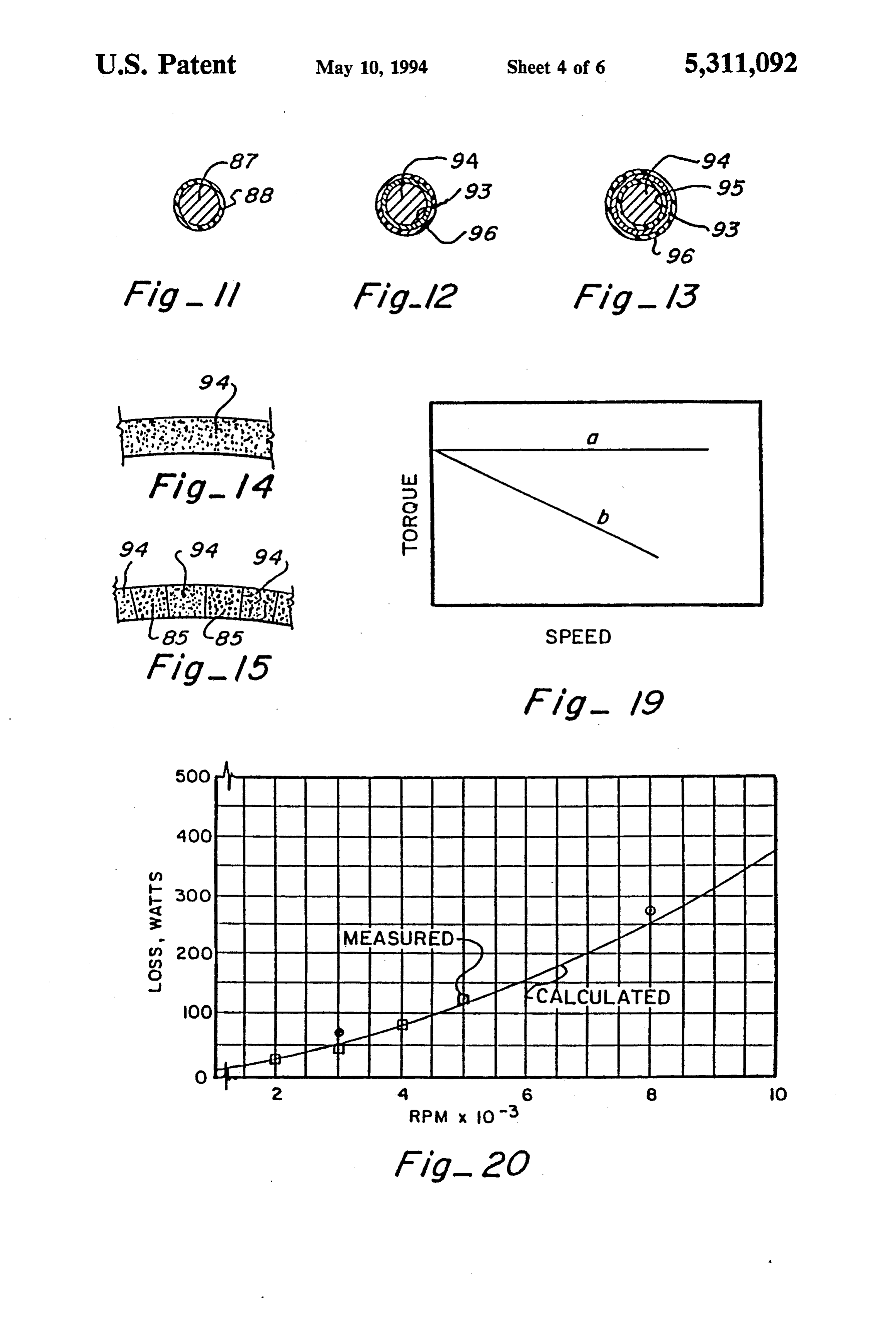
continuous operation at high power densities in excess FIG. 11 is a partial end view illustrating a dispersed of one horsepower per pound. conductor, as best shown in FIG. 4, and illustrating the It is still another object of this invention to provide an 15 insulation layer around the conductor; FIG, 12 is an end view similar to that of FIG. 11 but improved electromagnetic transducer having an arma ture assembly with dispersed conductors different sec illustrating an alternate embodiment of the armature tions of which have flux carrying elements positioned structure flux wherein the conductors have a coating of a carrying means (iron) thereon utilizable in lieu of therebetween with the conductors and flux carrying the flux carrying elements as illustrated in FIGS. 4 elements being formed and positioned in a manner so as 20 through 10;
to create low opposing induced currents.
It is still another object of this invention to provide an 12 FIG. 13 is an end view similar to that of FIGS. 11 and but illustrating another alternate embodiment of the improved electromagnetic transducer having an opti armature mum thickness armature assembly which represents a coating ofstructure a flux wherein insulated conductors have a carrying means (iron) thereon utiliz balance among the effects of heat transfer to the cooling 25 able in lieu of the flux carrying elements as illustrated in medium, heat production from resistance heating and FIGS. 4 through 10;
other sources, and torque production. FIG. 14 is a partial view illustrating the use of the With these and other objects in view, which will embodiment become apparent to one skilled in the art as the descrip ture without of use either FIG, 12 or FIG. 13 as the arma of separate flux carrying elements;
tion proceeds, this invention resides in the novel con 30
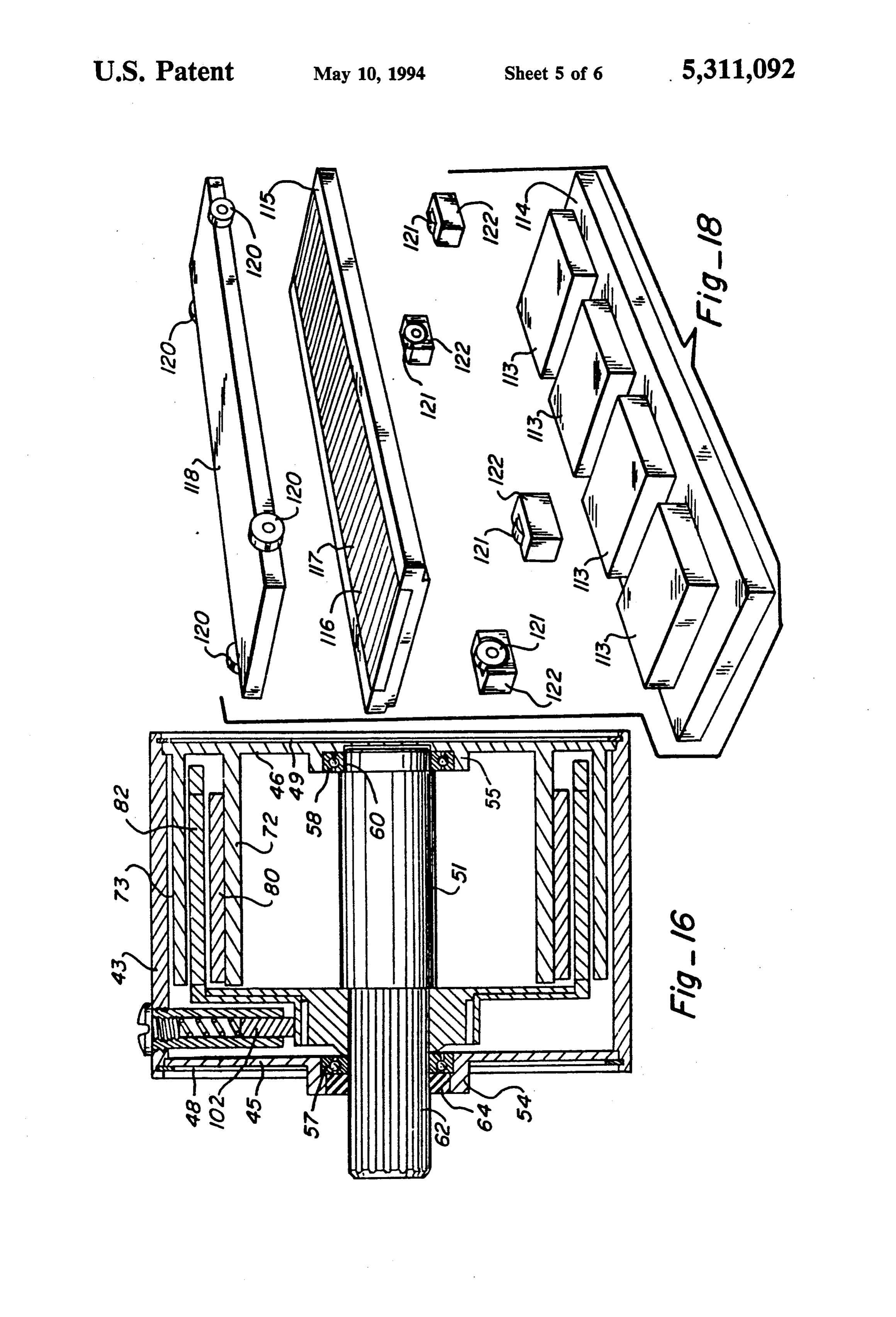
FIG. 15 is a partial view similar to that of FIG. 14 but struction, combination, and arrangement of parts sub illustrating use of alternating sections of dispersed con stantially as hereinafter described, and more particu ductors and dispersed conductors larly defined by the appended claims, it being under the embodiment of FIG. 12 or FIG.coated 13; as shown in stood that changes in the precise embodiments of the herein disclosed invention are meant to be included as 35 FIG. 16 is a side sectional view of an alternate em come within the scope of the claims. bodiment of the electromagnetic transducer as shown in FIG. 2, and illustrates the armature fixed to the shaft as
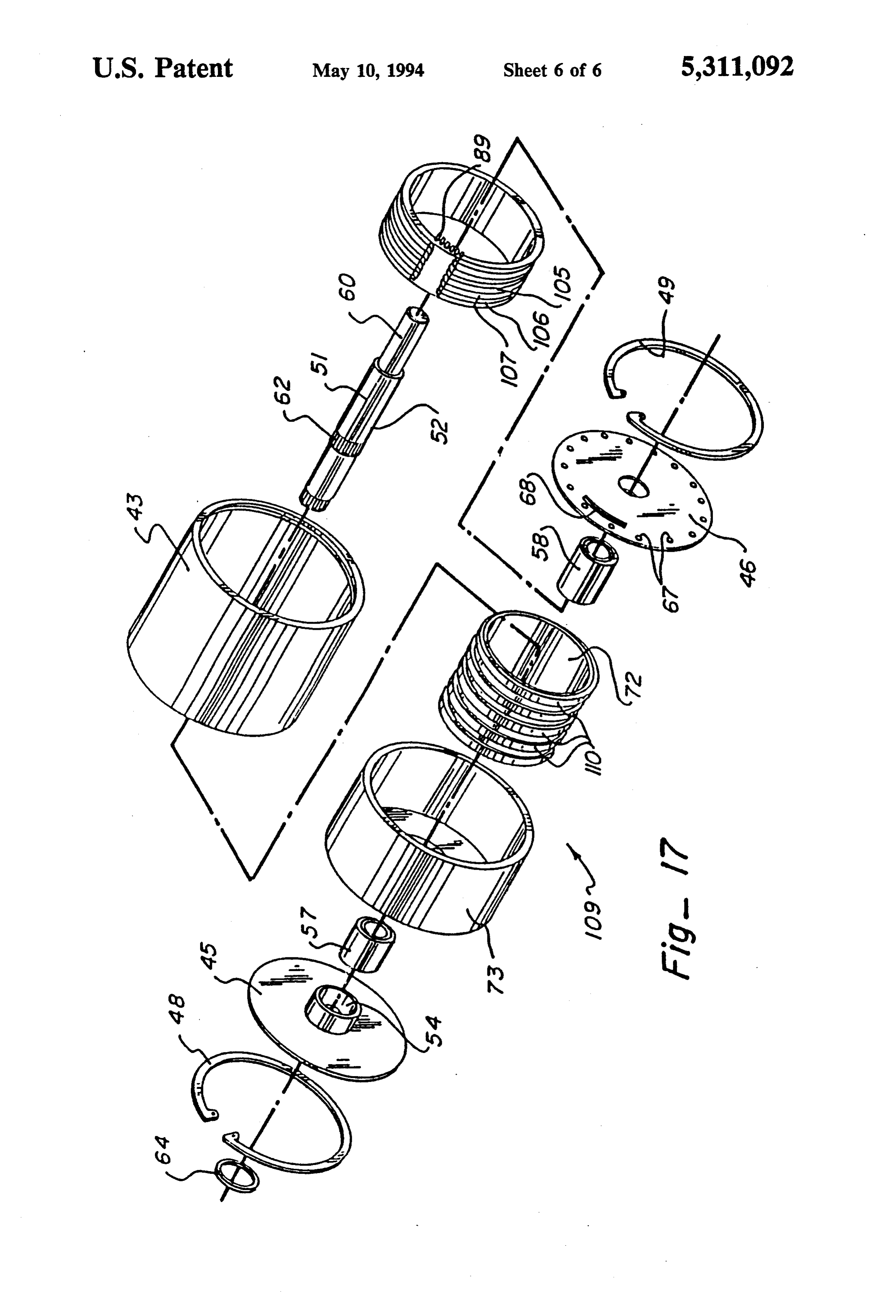
BRIEF DESCRIPTION OF THE DRAWINGS may be convenient to a brush commutated transducer; The accompanying drawings illustrate complete em FIG. 17 is an exploded isometric view of another bodiments of the invention according to the best mode alternate embodiment of the electromagnetic trans so far devised for the practical application of the princi ducer of this invention, and illustrates a cylindrically symmetric linear implementation thereof;
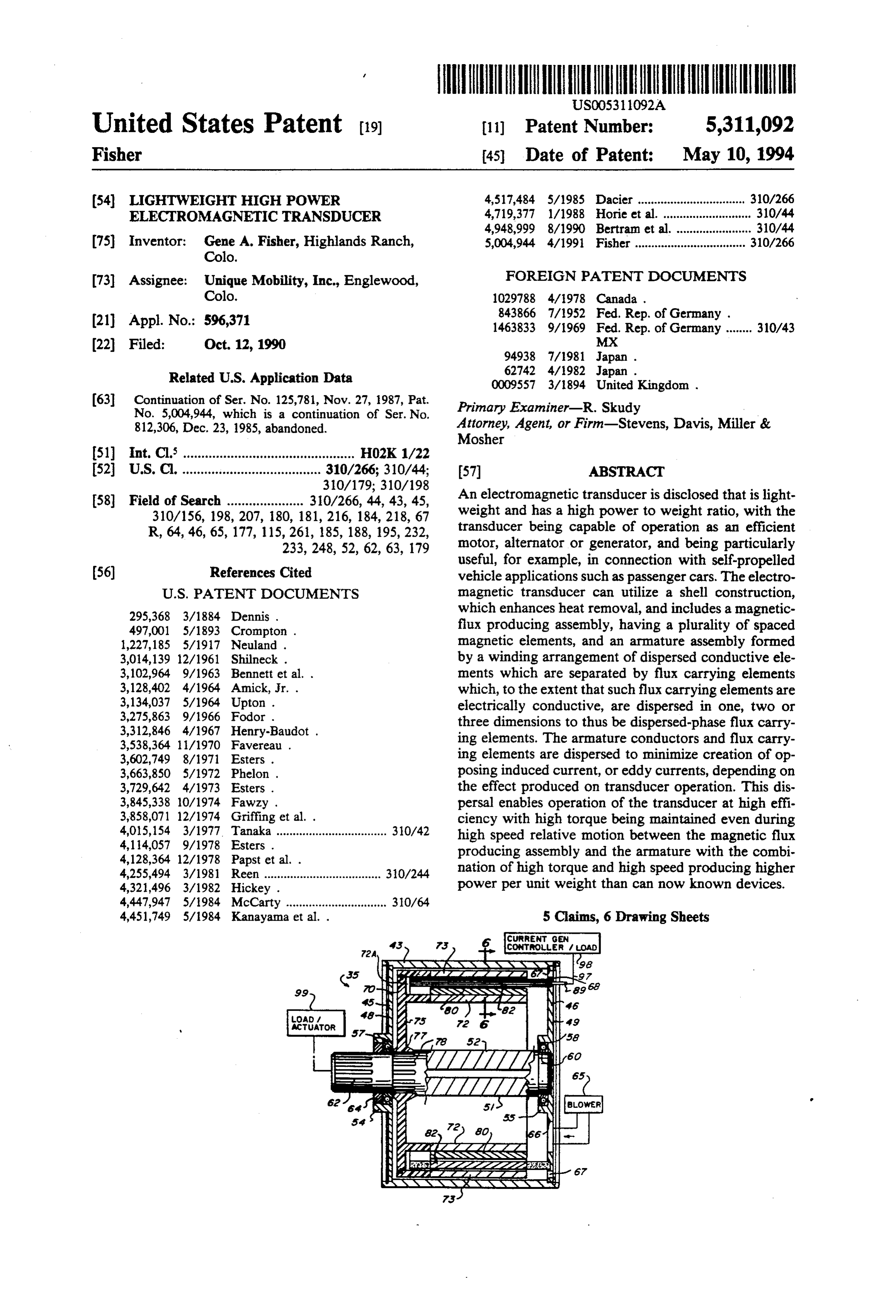
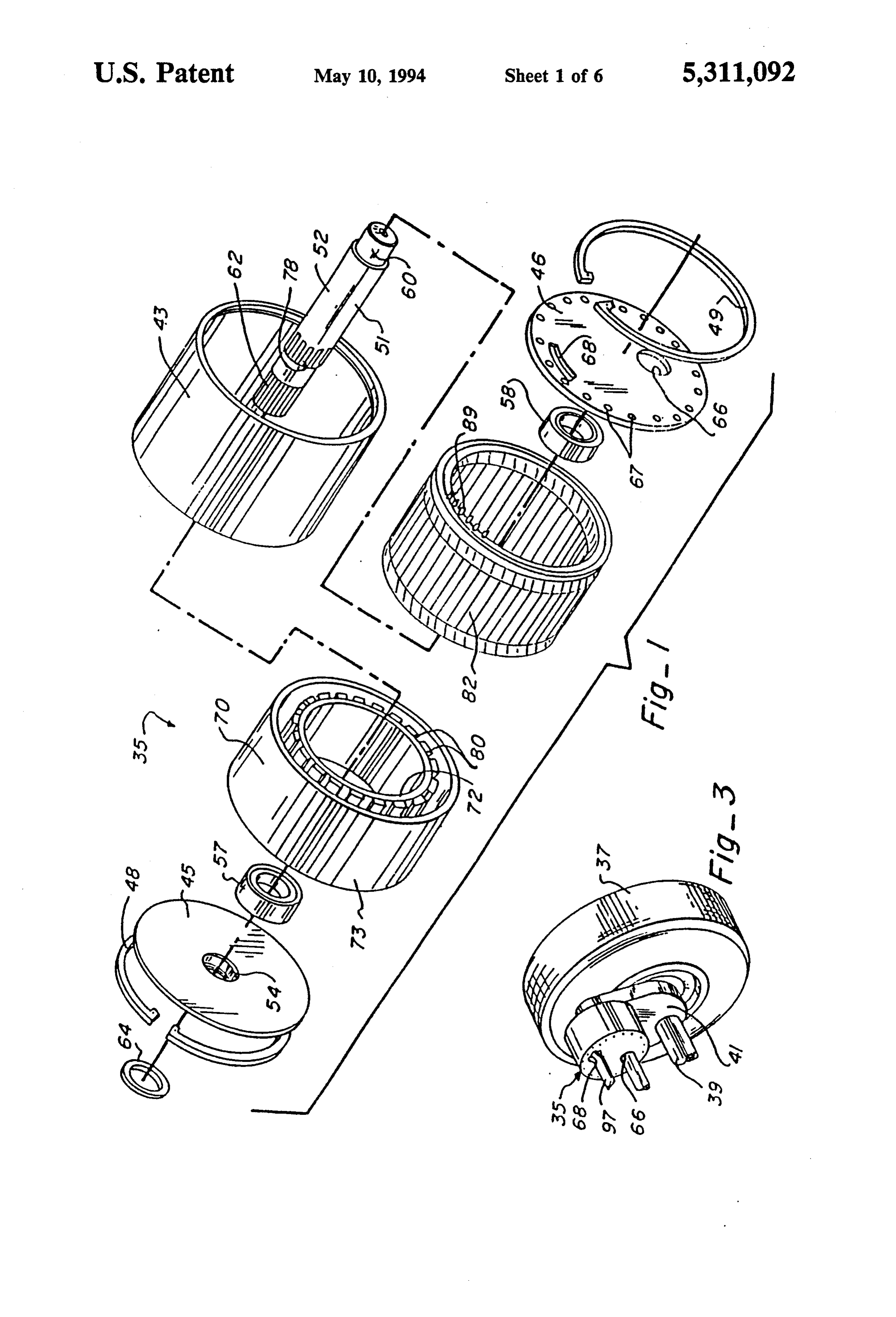
ples thereof, and in which: FIG. 18 is an exploded isometric view of still another FIG. 1 is an exploded isometric view of a rotary alternate embodiment of the electromagnetic trans implementation of the electromagnetic transducer of 45 ducer of this invention, and illustrates a flat linear imple this invention; mentation thereof;
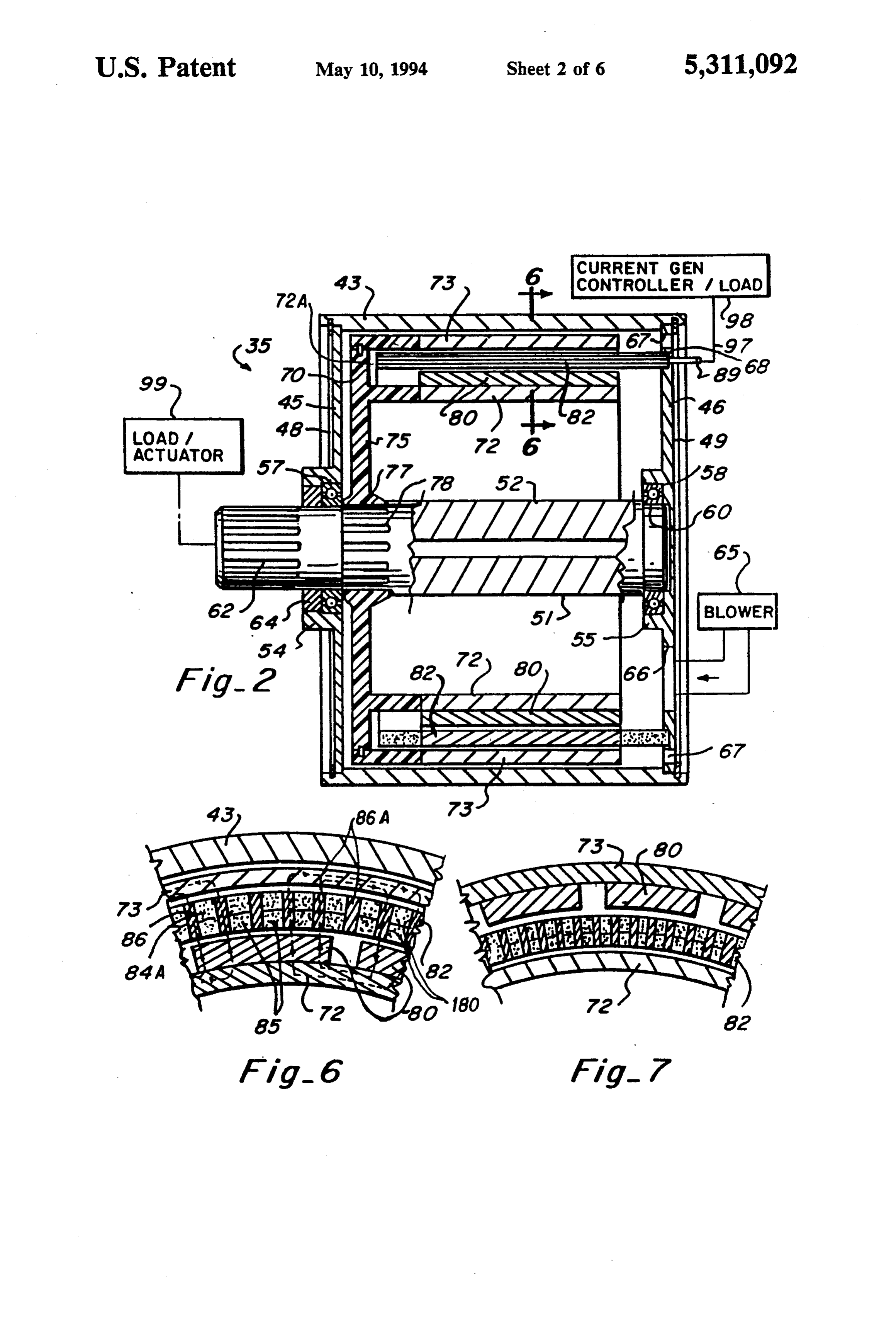
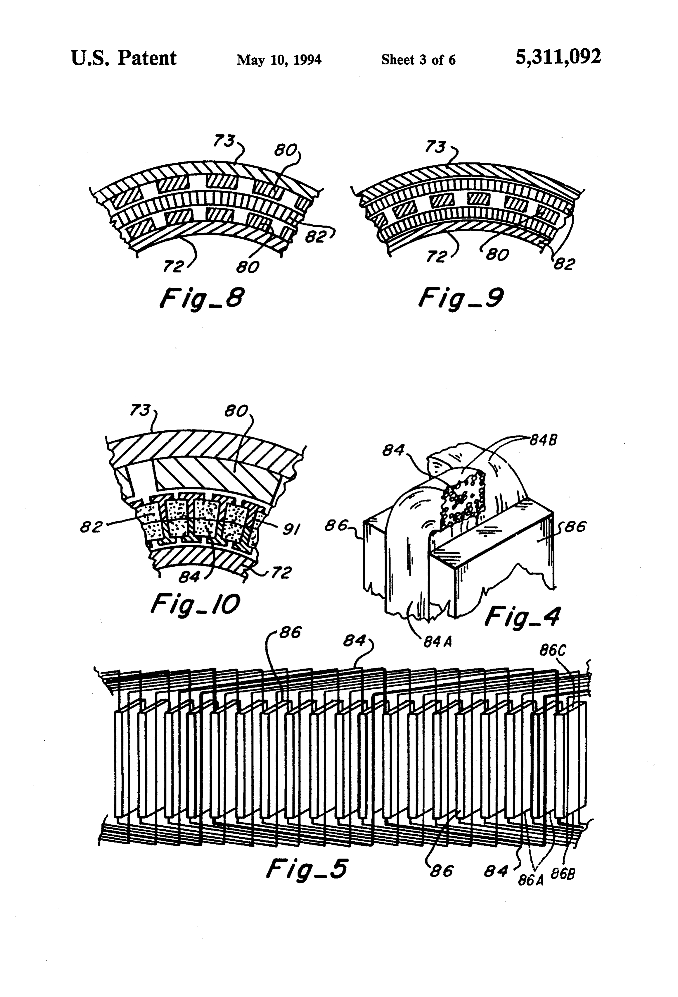
FIG. 2 is a side sectional view of the assembled elec FIG. 19 is a graph illustrating the relationship be tromagnetic transducer as shown in FIG. 1, along with tween torque and speed for a conventional transducer b additional elements illustrated in block form to better and for the transducer of this invention a; and illustrate the invention; 50 FIG. 20 is a graph illustrating tested eddy current, FIG. 3 is a partial isometric view illustrating use of hysteresis and windage losses at different speeds of one the electromagnetic transducer of this device config example of the transducer of this invention. ured as a traction motor to drive a wheel of an associ ated vehicle; DESCRIPTION OF THE INVENTON FIG. 4 is a partial isometric view showing the ar 55 A novel electromagnetic transducer is particularly rangement of the dispersed conductors and flux carry described herein, including alternate embodiments ing elements of the electromagnetic transducer shown thereof. It is meant to be realized that the electromag in FIGS. 1 and 2; netic transducer of this invention may be utilized as a FIG. 5 is a diagram illustrating a typical arrangement motor (ac or dc), alternator or generator, depending on of a two layer winding formed by the dispersed conduc whether an electrical signal is conveyed to the armature tors and illustrating the flux carrying elements posi (commonly through a commutator or equivalent struc tioned between turns of the windings; ture), to create a force causing movement of the mag FIG. 6 is a sectional view taken through lines 6-6 of netic flux producing structure relative to the armature FIG. 2, with the magnetic flux path in the transducer thus driving the shaft, or whether the shaft is rotated to also being illustrated; 65 thereby cause movement of the magnetic flux produc FIG. 7 is a partially cut-away view similar to that of ing structure relative to the armature to create an elec FIG. 6 but illustrating an alternate embodiment of the tromotive force which, in turn, can cause movement of electromagnetic transducer of this invention; current along the conductors of the armature to be
Page 10
coupled from the conductors as an electrical signal, as is tive to armature 82 (as well as to housing 43). Armature well known. 82 is thus a stationary cylindrical shell element that Electromagnetic transducer 35, as best shown in extends through the length of cylindrical housing 43 FIGS. 1 and 2, is lightweight and yet is capable of deliv between the inner and outer cylindrical walls 72 and 73 ering high power, with the transducer being a high of the rotor.
power density device that is particularly well suited, for It is important to this invention that armature 82 example, for use in conjunction with self-propelled include dispersed conductors 84, as best shown in FIG. vehicle applications, such as passenger cars, although 4, different sections 85 of which are positioned between the invention is not meant to be restricted thereto. flux carrying elements 80 as best shown in FIG. 6. The When used for vehicle propulsion, a permanent mag 10 conductors 84 have discrete, spaced apart active re net, hollow cylinder electromagnetic transducer 35 may gions 84A, as shown in FIGS. 4 and 5. As shown in be utilized as an efficient wheel mounted traction mo FIG. 6, active regions 84A have a substantially rectan tor, and may, as indicated in FIG. 3, be mounted di gular cross-section. Between active regions 84A are a rectly at each wheel 37, adjacent to axle 39, with drive plurality of discrete elongated open space areas 86A being preferably achieved through gear reduction 15 (see FIGS. 5 and 6). A flux carrying means formed of a mechanism 41. plurality of flux carrying members 86 of compressed As shown in FIGS. 1 and 2, electromagnetic trans iron powder are interposed in open space areas 86A ducer 35 includes an outer cylindrical housing 43, between active regions 84A. Dispersed conductors 84 which housing has front and rear end plates 45 and 46 are preferably formed from a bundle of small diameter positioned at the opposite ends of the cylindrical hous 20 copper wires 87 surrounded by insulating material 88 ing by means of snap rings 48 and 49. (as best shown in FIG. 11), with conductors 84 being A shaft 51 has a central portion 52 extending through wound into a linking pattern, as indicated by way of the cylindrical housing with the shaft being mounted in example in FIG. 5, with the opposite ends of the wire central hubs 54 and 55 of end plates 45 and 46, respec bundles being connected to connectors 89 extending tively, by means of bearings 57 and 58 so that the central 25 through aperture 68 in end plate 46, as indicated in FIG. portion of the shaft is coaxially positioned with respect 2.
to the cylindrical housing, the reduced diameter rear conductors 84, as best shown in FIG. 4, are formed portion 60 of the shaft is mounted in bearing 58, and the into a bundle throughout the armature (as by being front portion 62 of the shaft extends forwardly of front wound in a ring, for example), and each turn of the wire end plate 45, with seal 64 being positioned in hub 54 30 windings has a flux carrying element 86 therebetween, adjacent to bearing 57. as shown in FIGS. 5 and 6, with a typical winding As also shown in FIG. 2, blower 65 is positioned which constitutes a structurally integral annular wind adjacent to back, or rear, end plate 46, which plate ing structure, being conceptually illustrated in FIG. 5. includes offset air intake aperture 66 and a plurality of Flux carrying elements 86 are preferably iron (at least exhaust apertures 67 spaced about and near the periph 35 in part), and extend between the active region or length ery of the end plate. When so used, the transducer thus 84A of conductors 84. Elements 86 have radially inner operates in a gas (air) medium (as opposed to a fluid 86B and radially outer 86C elongated edges (see FIG. medium which could include oil or the like, for exam - 5). Conductors 84 also have flat end turns 84B at which ple, as do some known transducers). In addition, an the winding conductors 84 are reversed in direction (see arcuate aperture 68 is positioned to allow armature FIGS. 4 and 5) that extend beyond the active lengths conductor connections through end plate 46. 84A to connect the active lengths to each other in an As best shown in FIG. 2, rotor 70 has a double shell appropriate pattern, such as a wave winding as shown, configuration provided by inner and outer spaced cylin by way of example, in FIG. 5. The flux carrying ele drical portions 72 and 73 which extend normally from ments 86 are preferably dispersed-phase flux carrying mounting disk 75 so that cylindrical portions 72 and 73 45 members to handle the high frequency magnetic field are coaxial with, and inside, cylindrical housing 43 and reversals with low opposing induced currents and low define an annular gap 72A therebetween. Mounting disk eddy current losses. Because iron is electrically conduc 75 has an annular mounting portion 77 which is re tive, it must be dispersed to avoid (or at least minimize) ceived on splined portion 78 of shaft 51 inwardly of the creation of opposing induced currents. It has been bearing 57. 50 found that a suitable flux carrying element 86 can be Inner cylindrical portion 72 of rotor 70 has magnetic pressed from fine (10-100 m. kron) iron powder previ elements 80 mounted thereon, which magnetic elements ously reactively coated with phosphate insulation and are shown to be permanent magnets (but electromag using 'B' stage epoxy and wax as binders. nets could be utilized, if desired). Inner and outer walls By providing conductors comprising a plurality of 72 and 73, respectively, are formed of highly magneti 55 small diameter wires with dispersed-phase flux carrying cally permeable with low hysteresis loss magnetic mate elements between turns of the wires, opposing induced rial (such as iron or steel, for example), and mounting currents are minimized sufficiently so as to allow opera disk 75 is formed of non-magnetic material (such as tion of the electromagnetic transducer at high speeds plastic or aluminum, for example), while magnetic ele and at high torque with such operation being conducta ments 80 are high strength permanent magnets, which ble at high efficiency. In a working embodiment, a sta magnets are preferably formed of neodymium boron tionary armature shell incorporating windings of cop ferrite (NdFeB), but may also be formed of barium per with powdered iron bars to carry the magnetic flux, ferrite ceramic (BaFe Ceramic), samarium cobalt and permeated with glass re-enforced novolac epoxy (SmCo), or the like. insulation material cast as a bonding agent 180 between Armature 82 comprises an annular member at least 65 the windings and bars, has been successfully utilized. partially disposed within gap 72A and is fixed with In this invention when used as a motor, at constant respect to housing 43, and is mounted on rear end plate current, it has been found that the torque output can be 46, as indicated in FIG. 2, so that rotor 70 rotates rela maintained nearly constant even with increases in rotor
Page 11
speed, as illustrated in FIG. 19 by linea. This is quite The electromagnetic transducer of this invention thus unlike prior art devices wherein torque was found to includes a magnetic flux producing assembly (having at drop off rapidly with increased speed when solid bars least one pair of poles which can be embodied by using were utilized as conductors and as flux carrying ele permanent magnets or electromagnets), and an arma ments, as illustrated in FIG. 19 by line b. The combina ture assembly (which intercepts the magnetic flux pro tion of high torque and high speed, made possible in the duced by the magnetic flux producing assembly and has electromagnetic transducer of this invention, produces an alternating structure of conductive windings and flux high power density. carrying elements, which flux carrying elements can be As shown in FIG. 6, armature 82 (formed by the referred to as armature iron). A winding can be used as dispersed conductors 84 and flux carrying members 86) 10 the principal component of the armature with the wind are closely spaced with respect to magnets 80 posi ing consisting of bundles of separate conductors (which tioned about the inner cylindrical wall 72, and also are referred to herein as dispersed conductors), with the closely spaced with respect to cylindrical wall 73, with use of dispersed conductors of fine wire permitting high walls 72 and 73 providing inner and outer return paths, speed rotation of the rotor when used in conjunction respectively, for the magnetic flux. Some typical flux 15 with dispersed-phase flux carrying elements. paths have been illustrated in FIG. 6. As shown, these The use of multiple, parallel extending, insulated flux paths are loops each of which penetrates the arma conductors to reduce heating losses at high currents has ture twice passing principally through the flux carrying been heretofore suggested (see, for example, U.S. Pat. members 86. The flux carrying members thus allow a No. 497,001), and it is well known in the motor art as a thick armature to maintain a high flux density which is 20 method to reduce skin effect losses in motors. Skin essential to high torque. effect, however, causes losses at load only, whereas As indicated in FIG. 7, the electromagnetic trans eddy current losses, which would be experienced when ducer may also be configured by placing magnets 80 on known devices are rotated at high speed, occur at no outer wall 73 (rather than on inner wall 72). As indi load. This distinction is as to the mechanism of the cated in FIG. 8, the electromagnetic transducer may 25 effect.
also be configured by placing magnets 80 on both inner In the case of conductors of large cross section of and outer walls 72 and 73. conductive flux carrying elements of large cross sec As indicated in FIG. 9, an armature 82 can also be tion, as used at least in some prior known devices, as the provided at both sides of magnets 80. In addition, while frequency of the magnetic field reversal increases, the not specifically shown, it is also to be realized that the 30 magnitude of the induced currents in the bars increases, electromagnetic transducer could be configured by and the induced currents react with the magnetic field placing additional layers of armature-rotor elements to create a resisting torque which opposes the increase radially inwardly and/or outwardly of that shown in of rotational speed. Thus, known shell type devices are the drawings. While flux carrying members 86 in the inherently limited to low speed by the reaction torque, above embodiment are rectangular in cross-section, the 35 and cannot be rotated at high speed and are therefore flux carrying members may also be configured by utiliz unlike the device of the present invention, not suitable, ing a non-rectangularly shaped member such as, for for example, for use as traction motors in most practical example, an 1-shaped member 91 (as indicated in FIG. applications.
10) having dispersed conductors 84 extending therebe When used as a motor, a means to displace (i.e., ro tween. tate) the magnetic field relative to the armature at high The armature can also be configured as shown in speed must, of course, also be provided so that electric FIG. 12 such that flux carrying elements 93 are formed power can be converted into mechanical power in a as a coating of highly permeable magnetic material manner similar to that used by known motors. As indi (such as iron) on some or all of the dispersed conductors cated in FIG. 2, this can be accomplished by connecting 94. As indicated in FIG. 13, conductors 94 can also 45 leads 97 between connectors 89 of armature 82 and have an insulation layer 95 thereon so that insulation current generator and controller unit 98 so that unit 98 layer 95 is between the conductor and the flux carrying which provides current to conductors (see FIG. 10) to element. In either case, an insulating layer 96 covers the cause rotation of rotor 70, with rotation of rotor 70 flux carrying element (unless it is, of itself, electrically causing rotation of shaft 51 to drive a load/actuator 99. non-conductive). When used as an alternator or generator, load/actua When the flux carrying elements are formed as coat tor 99 causes rotation of shaft 51 which rotates rotor 70 ings on the dispersed conductors (as indicated in FIGS. to induce a voltage on conductors 84 and thereby gen 12 and 13), the flux carrying bars (shown in FIGS. 4 erates electrical current flow from conductors 84 to a through 10) need not be utilized. The dispersed conduc load 98. While not specifically shown in FIGS. 1 tors 94 with the flux carrying elements coated thereon 55 through 15, it is to be realized that the current generator can be utilized as the only elements of the armature (as and controller unit (or alternately the armature; in indicated in FIG, 14) or can be alternated with dis cludes necessary electric commutation devices, includ persed conductor sections 85, i.e., dispersed conductors ing those devices wherein commutation is performed having no flux carrying element coating thereon (as electronically (as in a brushless DC motor, for exam indicated in FIG. 15). 60 ple), as well as those devices which employ rectifiers Powdered iron utilized as flux carrying elements 86 instead of commutation (as is often used in power gener (as indicated in FIG. 6) provide three-dimensional ating applications).
phase dispersion, while flux carrying elements 93 FIG. 16 illustrates an embodiment of the electromag coated on the dispersed conductors (as indicated in netic transducer of this invention in which armature 82 FIGS. 12 and 13) provide two-dimensional phase dis 65 is connected with shaft 51, and inner and outer cylindri persion (iron lamination bars, on the other hand, when cal walls 72 and 73 are fixed to housing 43. In this en used as flux carrying elements provide only one bodiment, the armature thus becomes the rotor with dimensional phase dispersion). electric power being communicated with the armature
Page 12
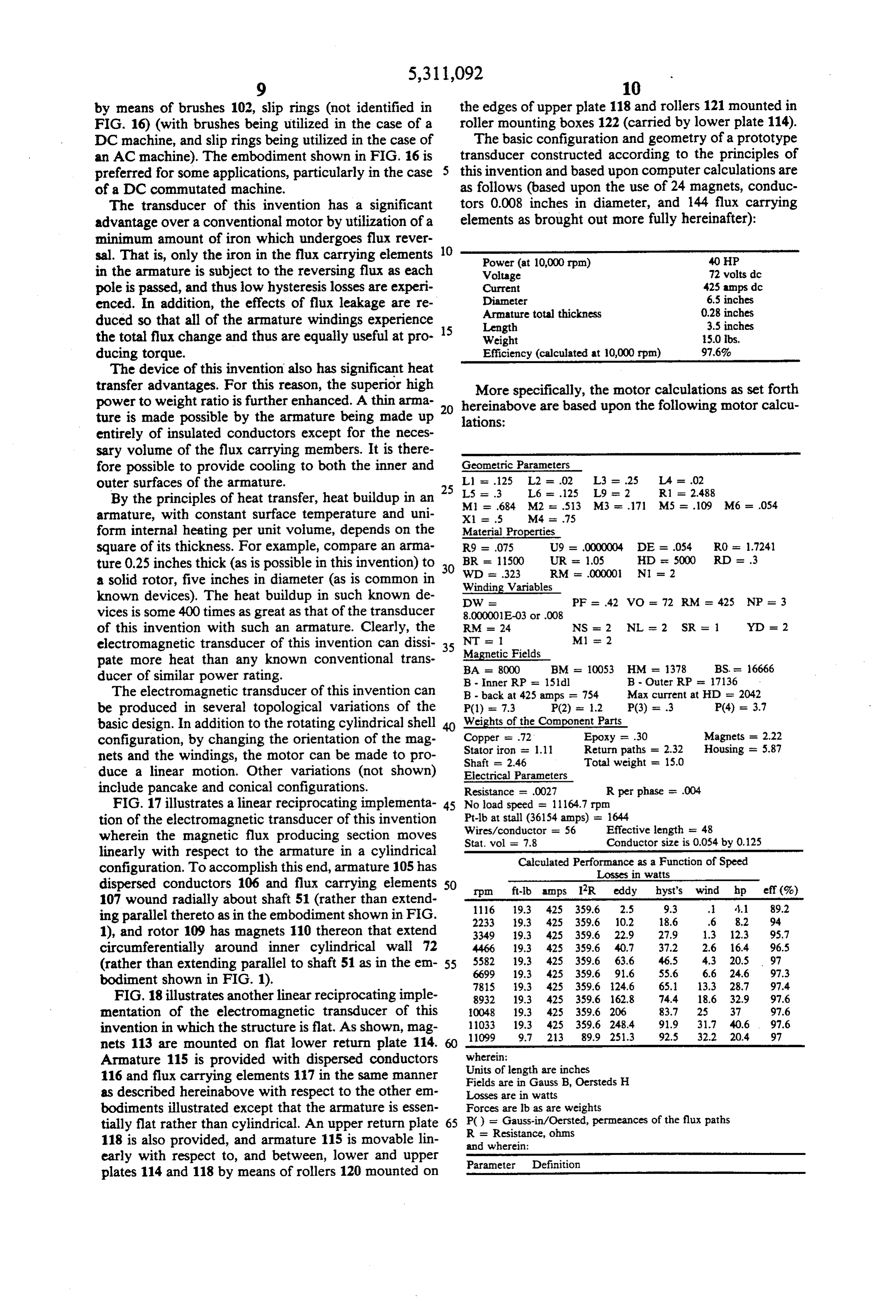
by means of brushes 102, slip rings (not identified in the edges of upper plate 118 and rollers 121 mounted in FIG. 16) (with brushes being utilized in the case of a roller mounting boxes 122 (carried by lower plate 114). DC machine, and slip rings being utilized in the case of The basic configuration and geometry of a prototype an AC machine). The embodiment shown in FIG. 16 is transducer constructed according to the principles of preferred for some applications, particularly in the case this invention and based upon computer calculations are of a DC commutated machine. as follows (based upon the use of 24 magnets, conduc The transducer of this invention has a significant tors 0.008 inches in diameter, and 144 flux carrying advantage over a conventional motor by utilization of a elements as brought out more fully hereinafter): minimum amount of iron which undergoes flux rever sal. That is, only the iron in the flux carrying elements Power (at 10,000 rpm) 40 HP in the armature is subject to the reversing flux as each Voltage 72 volts dc pole is passed, and thus low hysteresis losses are experi Current 425 amps dc enced. In addition, the effects of flux leakage are re diameter 6.5 inches Armature total thickness 0.28 inches duced so that all of the armature windings experience 15 Length 3.5 inches the total flux change and thus are equally useful at pro Weight 5.0 lbs. ducing torque. Efficiency (calculated at 10,000 rpm) 97.6% The device of this invention also has significant heat transfer advantages. For this reason, the superior high More specifically, the motor calculations as set forth power to weight ratio is further enhanced. A thin arma hereinabove are based upon the following motor calcu ture is made possible by the armature being made up lations:
entirely of insulated conductors except for the neces sary volume of the flux carrying members. It is there fore possible to provide cooling to both the inner and Geometric Parameters outer surfaces of the armature. L1 = .125 L2 = .02 L3 a .25 La = .02
By the principles of heat transfer, heat buildup in an MLS == 3.684 M2 L6 = .125 L9 se 2 R1 - 2.488
armature, with constant surface temperature and uni X1 = .5 M4 = .75 form internal heating per unit volume, depends on the Material Properties square of its thickness. For example, compare an arma R9 = .075 U9 = .0000004 DE = .054 RO = 1.7241
ture 0.25 inches thick (as is possible in this invention) to 30 WD UR = 1.05 HD is 5000 RD = 3
a solid rotor, five inches in diameter (as is common in Winding Variables known devices). The heat buildup in such known de OW - PF - 42 VO - 72 RM 425 NP = 3 vices is some 400 times as great as that of the transducer 8.000001E-03 or .008 of this invention with such an armature. Clearly, the RM = 24 NS = 2 NL = 2 SR = YD = 2 electromagnetic transducer of this invention can dissi 35 NT is 1 M1 se 2 pate more heat than any known conventional trans Magnetic BA = 8000
Fields
ducer of similar power rating. B - Inner RP = 15dl B - Outer RP = 17136 The electromagnetic transducer of this invention can B - back at 425 amps = 754 Max current at HD = 2042 be produced in several topological variations of the P(1) = 7.3 P(2) = 1.2 P(3) = .3 P(4) = 3.7 basic design. In addition to the rotating cylindrical shell Weights of the Component Parts configuration, by changing the orientation of the mag Copper = .72 Epoxy = .30 Magnets = 2.22 nets and the windings, the motor can be made to pro Stator iron = 1.1
Return paths = 2.32 Housing = 5.87
Total weight = 15.0 duce a linear motion. Other variations (not shown) Electrical Parameters include pancake and conical configurations. Resistance = .0027 R per phase = .004 FIG. 17 illustrates a linear reciprocating implementa 45 No load speed = 11164.7 rpm
tion of the electromagnetic transducer of this invention Wires/conductor wherein the magnetic flux producing section moves Stat. vol = 7.8 = 56 Conductor Effective length = 48
linearly with respect to the armature in a cylindrical configuration. To accomplish this end, armature 105 has Calculated Performance as a Function of Speed Losses in watts dispersed conductors 106 and flux carrying elements SO rpm ft-lb amps IR eddy hyst's wind hp eff(%) 107 wound radially about shaft 51 (rather than extend 1116. 19.3 425 359.6 2.5 9.3 . 4.1 89.2 ing parallel thereto as in the embodiment shown in FIG. 2233 9.3 425 3.59.6 10.2 18.6 .6 8.2 94. 1), and rotor 109 has magnets 110 thereon that extend 3349. 9.3 425 3.59.6 22.9 27.9 1.3 12.3 95.7 circumferentially around inner cylindrical wall 72 4466 19.3 425 3.59.6 40.7 37.2 2.6 16.4 96.5 (rather than extending parallel to shaft 51 as in the em 55 6699 5582. 19.3 425 3.59.6 63.6
bodiment shown in FIG. 1). 7815 9.3 425 359.6 24.6 65.1 3.3 28.7 97.4 FIG. 18 illustrates another linear reciprocating imple 8932, 19.3 425 3.59.6 62.8 74.4 18.6 32.9 97.6 mentation of the electromagnetic transducer of this 0.048 19.3 425 3.59.6 206 83.7 25 37 97.6 invention in which the structure is flat. As shown, mag 1033 19.3 425 3.59.6 248.4 91.9 31.7 40.6 97.6
nets 113 are mounted on flat lower return plate 114.
wherein:
Armature 115 is provided with dispersed conductors Units of length are inches 116 and flux carrying elements 117 in the same manner Fields are in Gauss B, Oersteds H as described hereinabove with respect to the other em Losses are in watts bodiments illustrated except that the armature is essen Forces are lb as are weights tially flat rather than cylindrical. An upper return plate 65 RP()= =Resistance,
Gauss-in/Oersted, permeances of the flux paths 118 is also provided, and armature 115 is movable lin and wherein: ohms early with respect to, and between, lower and upper plates 114 and 118 by means of rollers 120 mounted on Parameter Definition
Page 13
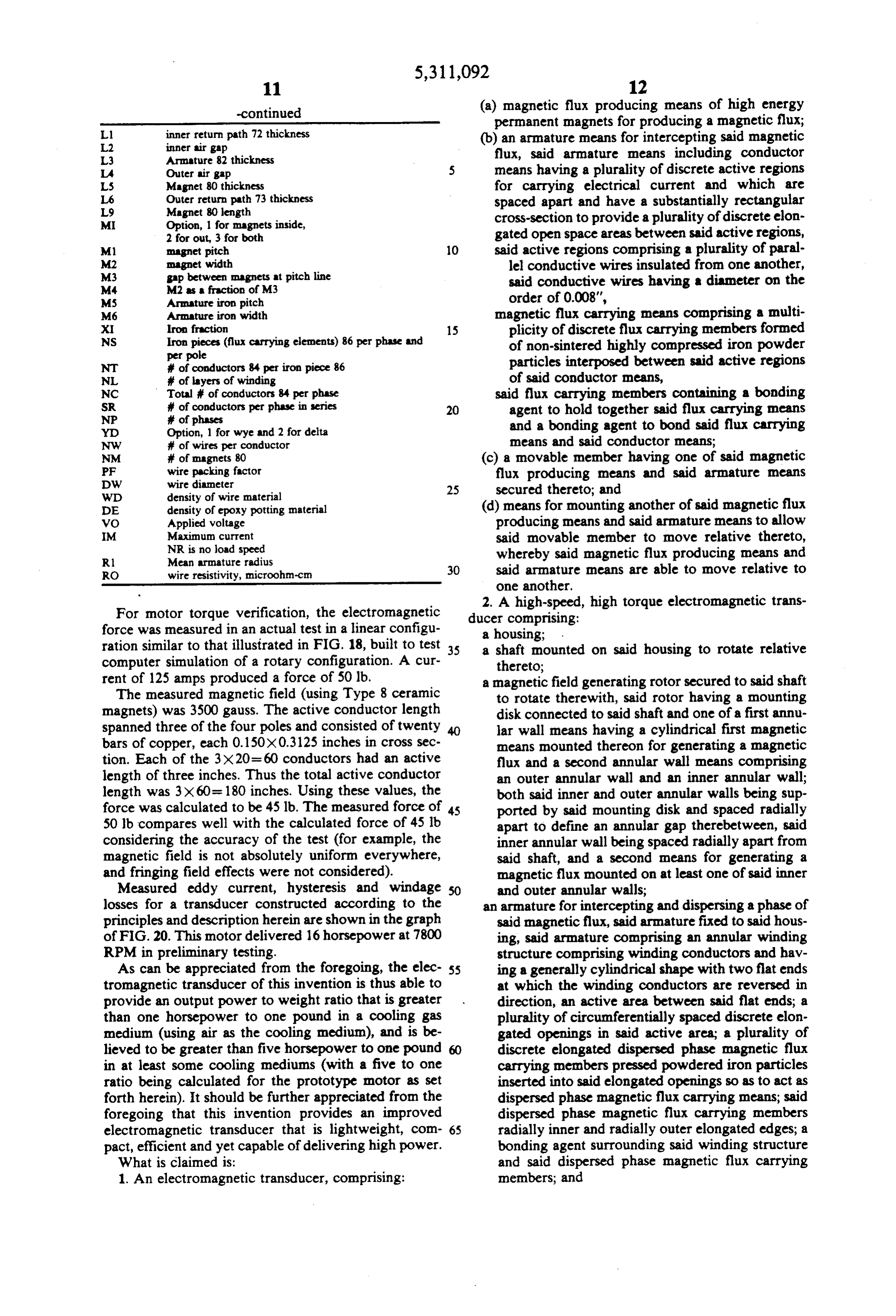
-continued (a) magnetic flux producing means of high energy permanent magnets for producing a magnetic flux;
Ll inner return path 72 thickness (b) an armature means for intercepting said magnetic L2 inner air gap
L3 Arnature 82 thickness flux, said armature means including conductor La Outer air gap means having a plurality of discrete active regions LS Magnet 80 thickness for carrying electrical current and which are
Outer return path 73 thickness
Magnet 80 length spaced apart and have a substantially rectangular
MI Option, 1 for magnets inside, cross-section to provide a plurality of discrete elon 2 for out, 3 for both gated open space areas between said active regions, M1 magnet pitch 10 said active regions comprising a plurality of paral M2 magnet width lel conductive wires insulated from one another, M3 gap between magnets at pitch line said conductive wires having a diameter on the
MS Arnature iron pitch order of 0.008',
M6 Arnature iron width magnetic flux carrying means comprising a multi
Iron fraction
Iron pieces (flux carrying elements) 86 per phase and 15 plicity of discrete flux carrying members formed per pole of non-sintered highly compressed iron powder NT # of conductors 84 per iron piece 86 particles interposed between said active regions NL # of layers of winding of said conductor means, NC Total of conductors 84 per phase said flux carrying members containing a bonding SR # of conductors per phase in series 20 agent to hold together said flux carrying means NP # of phases and a bonding agent to bond said flux carrying Yd Option, 1 for wye and 2 for delta
NW # of wires per conductor means and said conductor means; NM # of magnets 80 (c) a movable member having one of said magnetic PF wire packing factor flux producing means and said armature means DW wire diameter
WD density of wire material 25 secured thereto; and
DE density of epoxy potting material (d) means for mounting another of said magnetic flux VO Applied voltage producing means and said armature means to allow M Maximum current said movable member to move relative thereto, NR is no load speed whereby said magnetic flux producing means and R Mean armature radius
RO wire resistivity, microohm-cn 30 said armature means are able to move relative to one another.
2. A high-speed, high torque electromagnetic trans
For motor torque verification, the electromagnetic ducer comprising:
force was measured in an actual test in a linear configu a housing;
ration similar to that illustrated in FIG. 18, built to test 35 a shaft mounted on said housing to rotate relative computer simulation of a rotary configuration. A cur thereto;
rent of 125 amps produced a force of 50 lb. a magnetic field generating rotor secured to said shaft The measured magnetic field (using Type 8 ceramic to rotate therewith, said rotor having a mounting magnets) was 3500 gauss. The active conductor length disk connected to said shaft and one of a first annu spanned three of the four poles and consisted of twenty 40 lar wall means having a cylindrical first magnetic bars of copper, each 0.150X0.3125 inches in cross sec means mounted thereon for generating a magnetic tion. Each of the 3X20= 60 conductors had an active flux and a second annular wall means comprising length of three inches. Thus the total active conductor an outer annular wall and an inner annular wall; length was 3X60=180 inches. Using these values, the both said inner and outer annular walls being sup force was calculated to be 45 lb. The measured force of 45 ported by said mounting disk and spaced radially 50 lb compares well with the calculated force of 45 lb apart to define an annular gap therebetween, said considering the accuracy of the test (for example, the inner annular wall being spaced radially apart from magnetic field is not absolutely uniform everywhere, said shaft, and a second means for generating a and fringing field effects were not considered). magnetic flux mounted on at least one of said inner Measured eddy current, hysteresis and windage 50 and outer annular walls;
losses for a transducer constructed according to the an armature for intercepting and dispersing a phase of principles and description herein are shown in the graph said magnetic flux, said armature fixed to said hous of FIG. 20. This motor delivered 16 horsepower at 7800 ing, said armature comprising an annular winding RPM in preliminary testing. structure comprising winding conductors and hav As can be appreciated from the foregoing, the elec 55 ing a generally cylindrical shape with two flat ends tromagnetic transducer of this invention is thus able to at which the winding conductors are reversed in provide an output power to weight ratio that is greater direction, an active area between said flat ends; a than one horsepower to one pound in a cooling gas plurality of circumferentially spaced discrete elon medium (using air as the cooling medium), and is be gated openings in said active area; a plurality of lieved to be greater than five horsepower to one pound discrete elongated dispersed phase magnetic flux in at least some cooling mediums (with a five to one carrying members pressed powdered iron particles ratio being calculated for the prototype motor as set inserted into said elongated openings so as to act as forth herein). It should be further appreciated from the dispersed phase magnetic flux carrying means; said foregoing that this invention provides an improved dispersed phase magnetic flux carrying members electromagnetic transducer that is lightweight, com 65 radially inner and radially outer elongated edges; a pact, efficient and yet capable of delivering high power. bonding agent surrounding said winding structure What is claimed is: and said dispersed phase magnetic flux carrying 1. An electromagnetic transducer, comprising: members; and
Page 14
means for mounting said armature to allow said rotor particles interposed between said active regions to move relative thereto, whereby said rotor and of said conductor means, said armature are rotated relative to each other and said flux carrying members containing a bonding to said housing to provide high power output. agent to hold together said fluxing carrying 3. An electromagnetic transducer, comprising: means and a bonding agent to bond said flux (a) magnetic flux producing said means for producing carrying means, said compressed iron powder said magnetic flux; particles being 10-100 microns in diameter, and (b) an armature means for intercepting said magnetic said bonding agent comprising epoxy; flux, said armature means including conductor (c) a movable member having one of said magnetic means having a plurality of discrete active regions 10 flux producing means and said armature means for carrying electrical current which are spaced secured thereto; and apart and have a substantially rectangular cross (d) means for mounting another of said magnetic flux section to provide a plurality of discrete elongated producing means and said armature means to allow open space areas between said active regions, said movable member to move relative thereto, said active regions comprising a plurality of paral 15 whereby said magnetic flux producing means and lel conductive wires insulated from one another, said armature means are able to move relative to magnetic flux carrying means comprising a multi one another.
plicity of discrete flux carrying members formed 5. A high-speed, high torque electromagnetic trans of compressed fine iron powder particles of di ducer comprising:
ameter generally from 10-100 microns, said par a housing;
ticles being reactively coated with phosphate a shaft mounted on said housing to rotate relative insulation, thereto;
said flux carrying members being interposed be a magnetic field generating rotor secured to said shaft tween said active regions of said conductor to rotate therewith, said rotor having a mounting means, and a bonding agent comprising wax to 25 disk connected to said shaft and one of a first annu hold together said flux carrying means and said lar wall means having a cylindrical first magnetic conductor means; means mounted thereon for generating a magnetic (c) a movable member having one of said magnetic flux and a second annular wall means comprising flux producing means and said armature means an outer annular wall and an inner annular wall; secured thereto; and 30 both said inner and outer annular walls being sup (d) means for mounting the other of said magnetic ported by said mounting disk and spaced radially flux producing means and said armature means to apart to define an annular gap therebetween, said allow said movable member to move relative inner annular wall being spaced radially apart from thereto, whereby said magnetic flux producing said shaft, and a second magnetic means for gener means and said armature means are able to move 35 ating a magnetic flux mounted on at least one of relative to one another. said inner and outer annular walls; 4. An electromagnetic transducer, comprising: an armature for intercepting and dispersing a phase of (a) magnetic flux producing means of high energy said magnetic flux, said armature fixed to said hous permanent magnets for producing a magnetic flux; ing, said armature comprising an annular winding (b) an armature means for intercepting said magnetic structure comprising winding conductors and hav flux, said armature means including conductor ing a generally cylindrical shape with two flat ends means having a plurality of discrete active regions at which the winding conductors are reversed in for carrying electrical current and which are direction, an active area between said flat ends; a spaced apart and have a substantially rectangular plurality of circumferentially spaced discrete elon cross-section to provide a plurality of discrete elon 45 gated openings in said active area; a bonding agent gated open space areas between said active regions, surrounding said winding structure; and said active regions comprising a plurality of paral means for mounting said armature to allow said rotor lel conductive wires insulated from one another, to move relative thereto, whereby said rotor and magnetic flux carrying means comprising a multi said armature are rotated relative to each other and plicity of discrete flux carrying members formed 50 to said housing to provide high power output. of non-sintered highly compressed iron powder t k B six
Provenance
- Collection
- Cited prior art
- Original PDF
- patentimages.storage.googleapis.com →
- Filed
- 1990-10-12
- Pages
- 14
- Method
- pdftotext (the PDF's own text layer) + pdftoppm 300dpi page scans
- Source
- Google Patents bibliographic record
- Granted
- 1994-05-10
- Inventors
- Gene A. Fisher; Unique Mobility Inc
- Transcribed from
- patentimages.storage.googleapis.com →