patent · US5961124
Sealing system for a vertically disposed shaft
5 October 1999
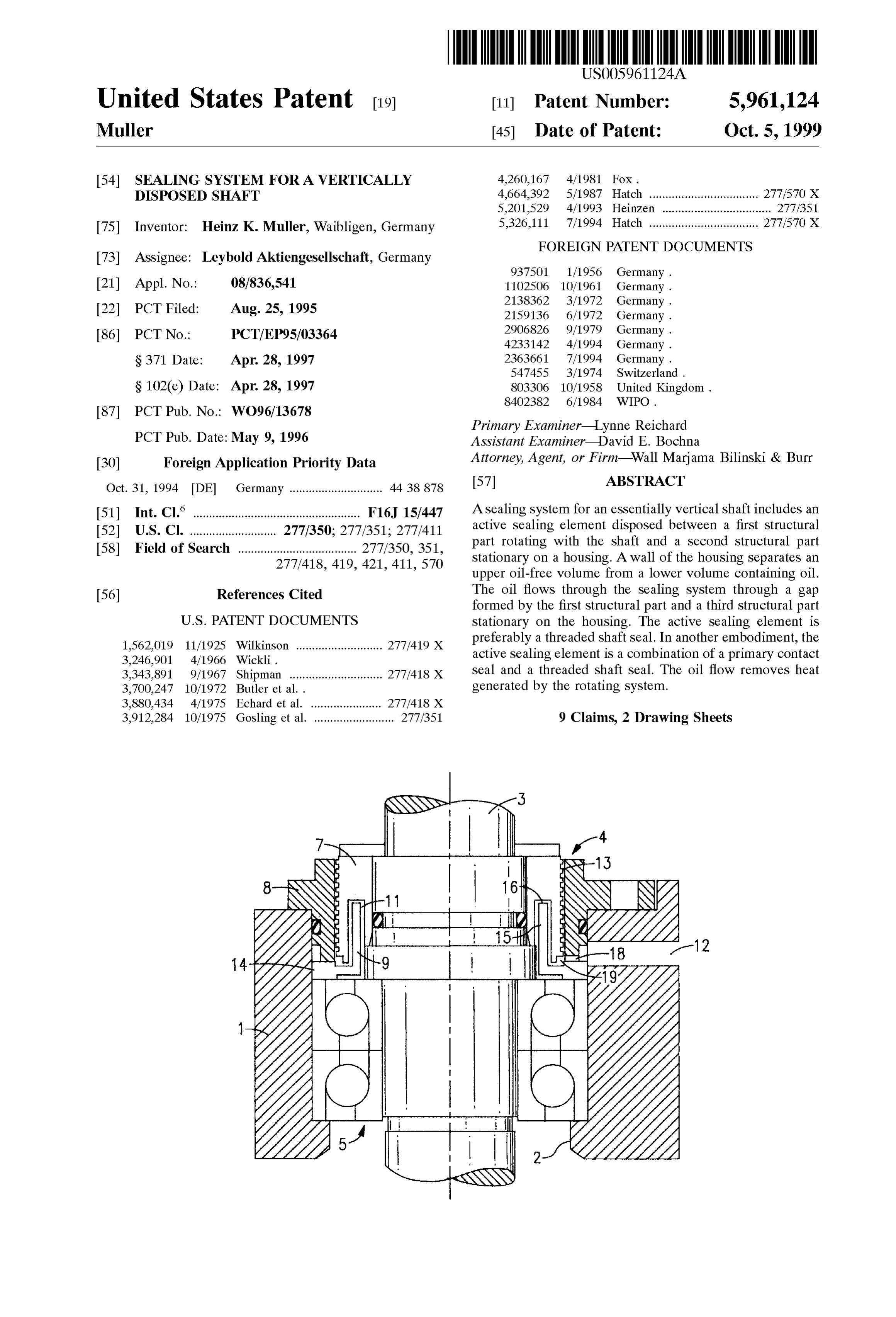
Page 1 — bibliographic record
United States Patent (19) 11 Patent Number: 5,961,124 Muller (45) Date of Patent: Oct. 5, 1999 54). SEALING SYSTEM FOR A VERTICALLY 4,260,167 4/1981 Fox.
DISPOSED SHAFT 4,664,392 5/1987 Hatch .................................. 277/570 X 5,201,529 4/1993 Heinzen .................................. 277/351 75 Inventor: Heinz K. Muller, Waibligen, Germany 5,326,111 7/1994 Hatch .................................. 277/570 X
FOREIGN PATENT DOCUMENTS
73 Assignee: Leybold Aktiengesellschaft, Germany
21 Appl. No.: 08/836,541 1102506 10/1961 Germany. 1.-1. 2138362 3/1972 Germany. 22 PCT Filed: Aug. 25, 1995 2159136 6/1972 Germany. 86 PCT No.: PCT/EP95/03364 2906826 9/1979 Germany.
S371 Date: Apr. 28, 1997 2363661 7/1994 Germany.
S 102(e) Date: Apr. 28, 1997 803306 10/1958 United Kingdom.
Primary Examiner-Lynne Reichard
PCT Pub. Date: May 9, 1996 ASSistant Examiner David E. Bochna 30 Foreign Application Priority Data Attorney, Agent, or Firm Wall Marjama Bilinski & Burr Oct. 31, 1994 DE Germany ............................. 44 38878 57 ABSTRACT (51) Int. Cl." .................................................... F16J 15/447 A Sealing System for an essentially vertical shaft includes an 52 U.S. Cl. ........................... 277/350; 277/351; 277/411 active Sealing element disposed between a first structural 58 Field of Search ..................................... 277/350,351, part rotating with the Shaft and a Second Structural part 277/418, 419, 421, 411, 570 Stationary on a housing. A wall of the housing Separates an upper oil-free Volume from a lower Volume containing oil.
56) References Cited The oil flows through the Sealing System through a gap formed by the first Structural part and a third structural part
1,562,019 11/1925 Wilkinson ........................... 277/419 X preferably a threaded shaft seal. In another embodiment, the 3.246,901 4/1966 Wickli. active Sealing element is a combination of a primary contact 3,343,891 9/1967 Shipman ............................. 277/418 X Seal and a threaded shaft seal. The oil flow removes heat 3,700,247 10/1972. Butler et al.. generated by the rotating System.
3,880,434 4/1975 Echard et al. ...................... 277/418 X 3,912.284 10/1975 Gosling et al. ......................... 277/351 9 Claims, 2 Drawing Sheets
Page 2
Drawing sheet — no readable text.
Page 3
Drawing sheet — no readable text.
Page 4
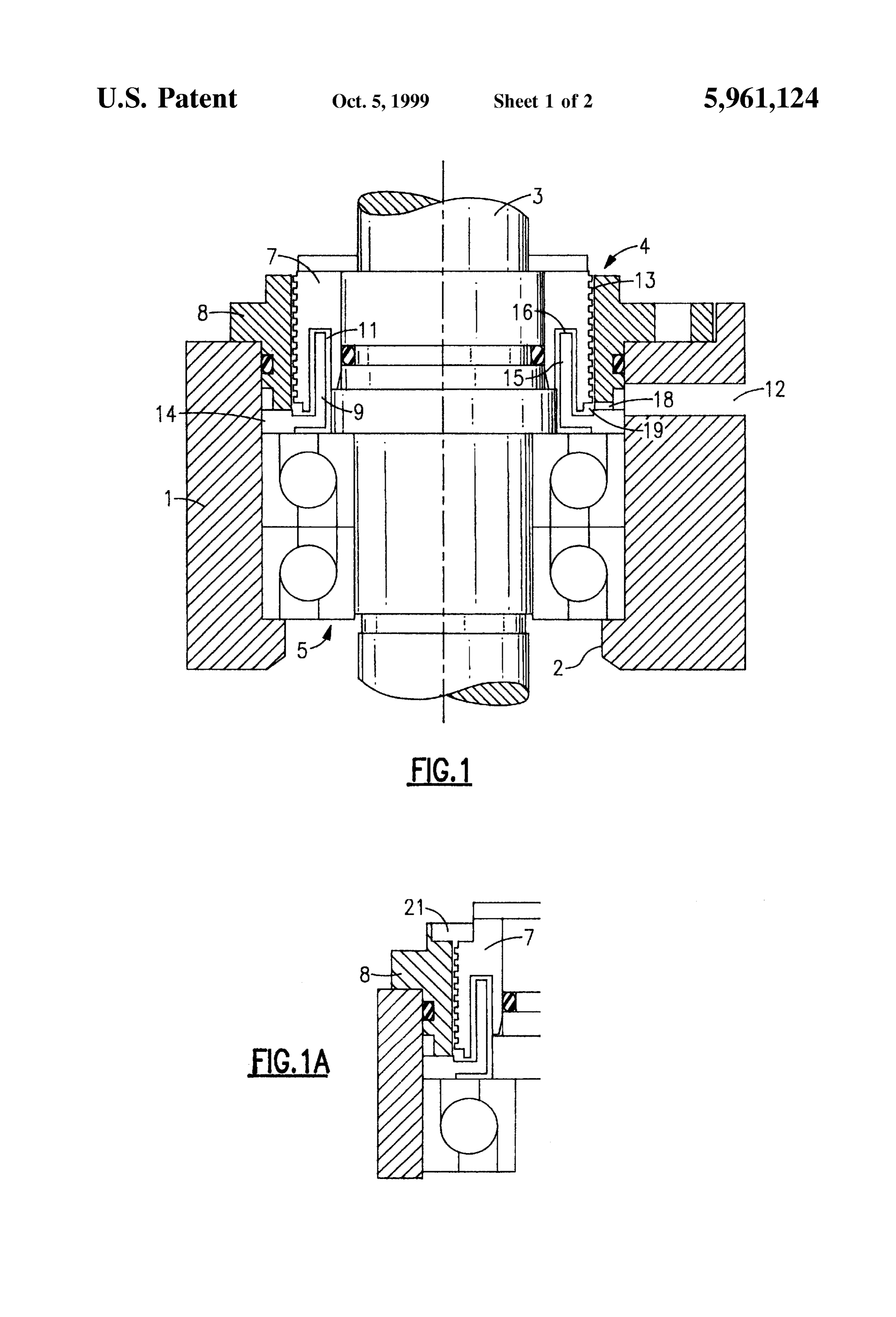
SEALING SYSTEM FOR A VERTICALLY penetrating the aperture 2 by 3, and a Sealing System Sealing DISPOSED SHAFT the Shaft 3 against the aperture 2 in general by 4. The BACKGROUND OF THE INVENTION housing wall 1 Separates for example in vacuum pumpS an upper oil-free volume (Suction chamber with low pressures,
The invention relates to a Sealing System disposed in the vacuum) from a lower oil-containing volume (gearing aperture through a housing wall, for an essentially vertical chamber, in which pressures exceeding the atmospheric shaft with an active Sealing element which is disposed pressure can occur). In the embodiment examples depicted between a Structural part rotating with the shaft and a the shaft 3 is Supported in the aperture 2. Bearings disposed Structural part Stationary on a housing, with the housing wall underneath the Sealing System 4 are denoted by 5. Separating an upper, oil-free Volume from a lower oil The Sealing System 4 comprises a structural part 7 rotating containing Volume.
Sealing Systems of this type are used for example in a with the shaft. Furthermore, two structural parts 8 and 9 vacuum pump such as is described in DE-A-42 33 142. In 8 (sealing on
Stationary the housing are present. The first Structural part the case of vacuum pumps of this type the elimination of the tural part 7.structural part 8) encompasses the rotating struc The second structural part 9 stationary on the heat generated in the rotating System presents problems. It develops, for one, due to the compression work of the rotors 15 housing forms together with the rotating Structural part 7 a in their Suction chambers and, for another, through the heat gap 11 through which flows oil. The Supply of the oil, due to friction of the contact Seals (radial shaft sealing) used. preferably PFPE oil, which is under slight excess pressure, SUMMARY OF THE INVENTION takes place via a bore 12 in the housing wall 1. Subsequently, as will be explained later in further detail, it
The present invention addresses the problem of creating a flows through the gap 11 and arrives through the bearing 5 Sealing System of the above cited type in which the elimi in the oil-containing Volume disposed underneath the bear nation of heat is significantly improved. ing 5.
This problem is solved according to the invention thereby In the embodiment example according to FIG. 1 the that through the Sealing System flows oil and that the rotating Structural part 7 and the Sealing structural part 8 Structural part rotating with the shaft as well as a further Stationary on the housing form a threaded shaft Sealing 13. Structural part Stationary on the housing form a gap through 25 The threads disposed on the rotating Structural part 7 are which the oil flows. The oil flowing through this gap implemented Such that with the shaft rotating oil penetrating absorbs, for one, heat from the Structural part rotating with from below into threaded shaft seal 13 is again transported the shaft and eliminates it. For another, the oil establishes a downwardly (recirculating threads). The oil rises at a given heat contact between the rotating Structural part and the preSSure difference in the recirculating threads until an Structural part Stationary on the housing So that via the equilibrium is reached between the pressure difference to be Structural part Stationary on the housing, and thus via the Sealed off and the recirculating pressure of the threads. The housing, the heat is eliminated. variable level of fill must remain less than the geometrically The Structural part and the further structural part Station available axial length of the recirculating threads. ary on the housing are usefully realized in the form of a The Second Structural part 9 Stationary on the housing labyrinth in their regions facing one another for the purpose 35 (gap-forming structural part 9) comprises a flange-form edge of extending the gap through which the oil flows. The 14 extending below the structural part 8 and a cylindrical cooling effect is thereby enhanced. In addition, a long gap of Segment 15 extending upwardly at the level of the rotating this type has the effect of a choke. This maintains exceSS structural part 7. This segment 15 extends free of contact pressure and thus continuous flooding without bubble for into an annular groove 16, open in the downward direction, mation at the oil inlet. in the rotating Structural part 7, and Specifically Such that the The active Sealing element can be a contact Sealing (shaft 40 gap 11 is formed.
Seal, collar sealing or the like) or a threaded shaft Seal. During operation of a machine with a Sealing System 4 Especially useful is a combination comprising a primary according to FIG. 1 the oil flows from the bore 12 through contact Seal and a Second threaded shaft Seal as auxiliary radial slots 18 into an annular volume 19 in which the Sealing. recirculating threaded gap 13 as well as also gap 11 termi The above, and other objects, features and advantages of 45 nate from above. Oil reaching the threaded gap 13 is the present invention will become apparent from the fol continuously carried back in order to ensure the desired lowing description read in conjunction with the accompa Sealing. The oil can therefore only flow out of the annular nying drawings, in which like reference numerals designate Volume 9 through gap 11, thus moving between the rotating the same elements. structural part 7 and the cylinder segment 15 initially BRIEF DESCRIPTION OF THE DRAWINGS 50 upwardly and Subsequently again downwardly. In this way it fulfills the task of absorbing heat from the rotating
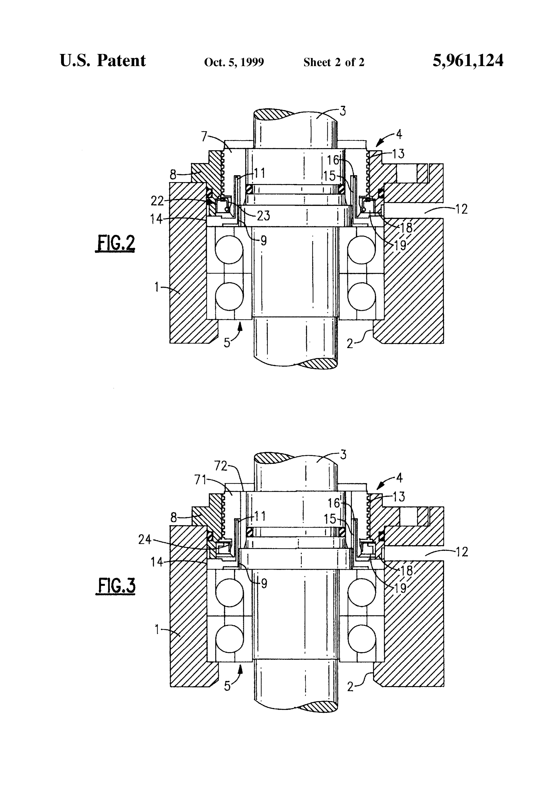
FIG. 1 shows a Sectional view of a Sealing System with a Structural part in order to eliminate the heat itself or to threaded shaft Seal according to an embodiment of the transfer it to the Structural part Stationary on the housing. invention. The width of the gap is usefully smaller than 1 mm, FIG. 1a shows a sectional view of a sealing system with 55 preferably 0.3 mm.
a threaded shaft Seal according to a variation of the embodi In the case of using the Solution according to FIG. 1 in a ment of FIG. 1. Vacuum pump, the following must be considered: if the FIG. 2 shows a Sectional view of a Sealing System with a pump is stored while it is still warm from operation (for threaded shaft Seal according to an embodiment of the example at 80 C. and thus at a gearing volume pressure, invention. generated by thermal expansion, of approximately 1.3 bars), FIG. 3 shows a sectional view of a sealing system with a 60 the recirculating pressure of the threaded shaft Seal 13 threaded shaft Seal according to an embodiment of the diminishes instantaneously. Consequently the persisting invention. gearing Volume preSSure will force the oil contained in the DETAILED DESCRIPTION OF THE threaded gap upwardly into the delivery volume of the
PREFERRED EMBODIMENT
pump. In order to Solve this problem, it is Suggested to 65 provide an expanded annular volume 21 above the reciru
In all Figures the housing wall is denoted by 1, an aperture lating thread 13 (depicted in FIG. 1a) in which in the provided in the housing wall 1 by 2, a vertical shaft described case the oil can be collected without penetrating in
Page 5
fact into the pump Volume. When the pump is started again, be an integral component of the Shaft 3 or the housing wall the threads immediately return the oil in the expanded 1. In the last case, however, their fabrication is difficult. This annular volume 21 unless the oil has returned by itself after applies in particular to the rotating Structural part 7. In the a relatively long Standstill in connection with the cooling of embodiment according to FIG. 3, due to annular groove 16 the gearing Volume. which could otherwise only be produced with difficulty, In the embodiment example according to FIG. 2, in rotational Structual parts comprises two eSSentially cylindri addition to the threaded Shaft Seal 13, a contact Seal is cal parts 71, 72 which are connected by means of shrink provided and Specifically a radial Shaft Sealing ring 22 fitting or hard-Soldering and which form the annular groove (RSSR 22). It is disposed in the annular volume 19, and 16 between them.
specifically underneath the threaded shaft seal 13. Its dis Having described preferred embodiments of the invention position is Selected Such that its Sealing lip 23 together with with reference to the accompanying drawings, it is to be the rotating Structural part 7 forms an-internally located understood that the invention is not limited to those precise Sealing site. The open Side of the Sealing ring 22 faces the embodiments, and that various changes and modifications oil-containing Volume. The Spacing of the Sealing Site from may be effected therein by one skilled in the art without the gap 11 through which oil flows is as Small as possible So 15 departing from the Scope or Spirit of the invention as defined that an effective cooling of the Sealing site is achieved. In in the appended claims.
this embodiment example, RSSR 22 initially seals off the oil What is claimed is:
in conventional manner. In order to attain optimum Service 1. A Sealing System for use in a vacuum pump equipped life of the RSSR 22, a low specific radial force, preferably with a vertical shaft, Said Sealing System comprising: less than 0.15 N/mm, should be ensured. For this purpose the a Stationary housing;
RSSR 22 can be installed without a spring. In contrast to a vertically disposed shaft mounted for rotation within conventional configurations, the RSSR 22 runs on a thin Said housing, walled tubular extension of the rotating Structural part 7. a Seal means connected to Said shaft for rotation with the This allows for the contacting Sealing Site to be cooled especially Strongly from the inside and from the outside. shaft within Said housing, Said Seal means having a top Due to the low radial force, on the one hand, and the cooling 25 and a bottom Surface, Said Seal means includes a of the Sealing Site, on the other hand, a considerable increase rotating threaded Shaft Seal having an outer Surface, of the service life of the RSSR 22 can be expected in contrast Said outer Surface adjacent an inner Surface of Said to conventional dispositions of RSSR. housing and forming a first Space; As soon as a leak occurs on RSSR 22 which goes beyond a cylindrical groove within Said Seal means extending the holding capacity of the annular volume 19 above the upward from the bottom Surface; and RSSR 22, the recirculating threads 13 become active. The a cylindrical Segment disposed within Said groove to higher the oil rises with further leakage in the recirculating provide a gap between adjacent Surfaces of the groove threads 13, the higher becomes the liquid pressure generated and the Segment which creates a flow path, whereby by the threads on the topside of the RSSR 22. Thereby the cooling oil can be conducted through said flow path, RSSR 22 becomes increasingly free of loading and finally 35 Said cylindrical Segment being connected to Said hous runs nearly free of friction. Nevertheless, when the pump is Ing.
taken out of operation, if the pressure of the threads 2. The Sealing System of claim 1, including an expanded diminishes, the RSSR 22 Seals the gap again completely So annular Volume disposed adjacently above Said first Space. that no oil can be pushed through in the upward direction though the exceSS pressure in the gearing Volume. An oil 40 is 3.inThe Sealing System of claim 1, wherein Said first Space communication with Said gap through an annular collection volume 21, as was described in connection with Volume, Said oil being able to flow into Said gap, into Said the Solution according to FIG. 1, can thus be omitted. During annular Volume, and into Said first Space. the next start, the threads immediately transport the oil in the 4. The Sealing System of claim 1, including a Second Seal, downward direction. In the process, the RSSR 22 is lubri Said Second Seal being a radial shaft Sealing ring disposed cated from above and Simultaneously the load is removed. below Said rotating Shaft Seal.
If, in the pump which in the meantime has cooled, the 45 5. The sealing system of claim 1, wherein said oil is preSSure in the gearing Volume is still relatively low, the introduced into a lower portion of Said first Space for an RSSR, impressed from above, can allow oil to penetrate upward directional downwardly whereby the recirculating threads can poten shaft Seal provides flow, a and wherein Said rotating threaded recirculating pressure that transports tially become partially or completely pumped empty. In Said oil back into a downward directional flow as Said oil addition, during the start, the RSSR 22 prevents that oil 50 rises through Said Seal.
adhering on the Sealing gap walls from being Suctioned 6. The Sealing System of claim 1, including a Second Seal, upwardly into the delivery Volume of the pump. Said Second Seal being a collar Seal disposed below Said In the embodiment example according to FIG. 3 a PTFE rotating Shaft Seal.
collar seal (PTFE collar 24) is provided as a primary contact 7. The Sealing System of claim 1, including a Second Seal, Seal. An advantage of this primary Seal, compared to the 55 Said Second Seal being a contact Seal.
RSSR22 according to FIG. 2, is the greater pressure bearing 8. The Sealing System of claim 7, wherein Said contact Seal capability and thermal stability of the PTFE shaft sealing is disposed in an annular volume below Said rotating ring. For the remainder the configuration and the functions threaded Seal, and wherein Said contact Seal Separates the of this Solution correspond to the Solution according to FIG. lower entrance of the first Space with the entrance of the gap. 2. 60 9. The sealing system of claim 7, wherein said contact seal AS described, the Sealing System 4 comprises a rotating has a low specific radial force.
structural part 7 and two structural parts 8 and 9 stationary on the housing. These could each comprise Several parts or k k k k k
Provenance
- Collection
- Cited prior art
- Original PDF
- patentimages.storage.googleapis.com →
- Filed
- 1995-08-25
- Pages
- 5
- Method
- pdftotext (the PDF's own text layer) + pdftoppm 300dpi page scans
- Source
- Google Patents bibliographic record
- Granted
- 1999-10-05
- Inventors
- Heinz K. Muller; Leybold AG
- Transcribed from
- patentimages.storage.googleapis.com →