patent · US3072813
Rotor having a plurality of permanent magnets arranged on their periphery
8 January 1963
Page 1
Drawing sheet — no readable text.
Page 2
United States Patent Office 1.
Patented Jan. 8, 1963
3,072,813 In the structure according to the invention, the ring ROTOR HAVING A PLURALITY OF PERMAN ENT of non-magnetic material is the structure which absorbs MAGNETS ARRANGED ON THER PERPHERY the centrifugal forces. In connection therewith, the Maximilien Felix Reijinst and Wilheimus Hendrikus van strength of the ring is to be chosen dependent upon the Donselaar, Eindhoven, Netherlands, assignors to North
American Philips Company inc., New York, N.Y., a speed of rotation of the rotor.
It has been found possible to give the ring of non corporation of Delaware
Filed Sept. 29, 1958, Ser. No. 764,147 magnetic material a width smaller than that of the pole Claims priority, application Netherlands Oct. 22, 1957 plates. The thickness of the ring must then be chosen 5 Claims. (C. 310-156) - correspondingly, the pole plates themselves usually being 0. strong enough to avoid any troublesome deformation dur
This invention relates to rotors having a plurality of ing operation.
permanent magnets arranged on their periphery. The width of the ring of non-magnetic material is According to the invention, the magnets consist of a preferably about 4 of the width of the pole plates. material having an H higher than 1000 oersted whereas In order to give the ring of non-magnetic material a their poles of equal polarity are adjacent one another and 5 sufficiently high tensile strength, it is preferably made of the magnets separated by pole plates are located in juxta chrome-nickel steel.
position in the tangential direction and held in the radial Optimum results in magnetic respect are obtained if the direction by the direct support of, and/or attachment to cross-section of the magnets at right angles to the shaft the pole plates, which on the inner side are secured to a of the rotor is rectangular and that of the portion of the ring of non-magnetic material arranged on the shaft of pole plates located 20 between the magnets is substantially the rotor.
This application is a continuation-in-part of applica togetherin a trapezoidal shape. The thickness of the pole plates thus increases with the increasing magnetic flux.
tion Serial No.
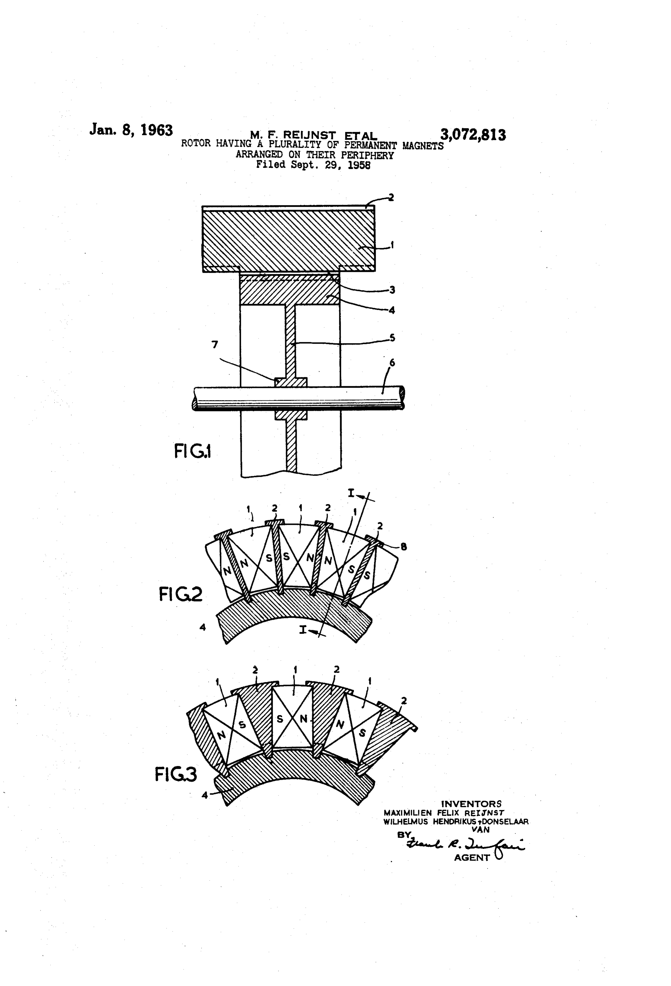
690,009, filed October 14, 1957, now U.S. In order that the invention may be readily carried into By the particular choice of the magnetic material and 25 way effect, one embodiment will now be described in detail, by the location of the magnetic poles with respect to one an ing, of example, with reference to the accompanying draw
other, it is possible to build up a rotor having a large FIG. 1 is a cross-sectional view of the shaft of the rotor number of alternating poles without a large pitch of the according to the invention;
poles being necessarily involved. Due to their large num FIG. 2 is a cross-sectional view at right angles to the ber, it is then not readily possible for the magnets to be 30 shaft of the rotor according to the invention; secured themselves directly to the shaft, for example by FIG. 3 shows a variant of the embodiment of FIG. 2. means of a screwed connection or an adhesive. Further The figures show a rotor provided on its periphery with more, the forces resulting from the centrifugal action may a plurality of permanent magnets 1 each consisting of a be such that the magnets are required to be secured very material having an He greater than 1000 oersted. Pole rigidly. It would be possible for the magnets to be se 35 plates 2 are located between the magnets 1, which are cured to a cylindrical supporting body surrounding the magnetized in the tangential direction and have their poles rotor and secured to the shaft. However, the air-gap be of equal polarity adjacent one another so that alternately tween the rotor and a surrounding part, which co-acts north and south poles are formed by the pole plates 2 with it, is thus increased to an undesirable extent, so that 40 on the periphery of the rotor. The pole plates 2 are se the advantages obtained with the structure according to the invention would partly be lost again. Another solu cured steel.
on their inner side 3 to a ring 4 of chrome-nickel
The width of the ring 4 is approximately /3 of tion could be by providing the pole plates with cams the width which project from the magnets on the sides of the rotor means of of the pole plates 2. The ring 4 is secured by a plate 5 which may be of the same material and which are surrounded by an annular body secured 45 as the ring 4 via a nave 7 to the shaft 6 of the rotor. to the shaft. However, the surface pressures which oc In FEG. 2 the permanent magnets 1 have trapezoidal cur in this construction may become such that the ma terial of which the pole plates are built up cannot with 2cross-section, located the thickness of the portion of the pole plates between the magnets 1 being the same through stand such pressures. Furthermore, as a result of the Cult. - centrifugal forces occurring, the pole plates in this struc ture are subject to bending stress, so that the strength of 50 tionin the FIG. 3, the magnets 1 have a rectangular cross-sec thickness of the portion of the pole plates 2 the pole plates must in certain cases be greater than is located between the magnets 1 increasing towards the ex desirable in magnetic respect. By holding the magnets in terior.
the radial direction by the direct support of, and/or at The magnets 1 are held in radial direction by means of tachment to the pole plates, which pole plates are se a widened part 8 of each pole plate 2. Besides, the mag cured on their inner side to a ring of nonmagnetic mate nets 1 are attached to the pole plates 2 with the aid of rial arranged on the shaft of the rotor, it is achieved in an adhesive.
a simple manner, that the magnets are secured to the What is claimed is:
shaft by means of the pole plates already present. This 1. A rotor comprising a shaft, a plurality of permanent requires only the use of a ring of non-magnetic material 60 magnets radially disposed about said shaft, each of said arranged on the shaft of the rotor, so that a very simple magnets being constituted of a material having a coercive and compact structure is obtained which is readily ac force (H) greater than about 1000 oersted, said magnets cessible. The ring of non-magnetic material may be ar being disposed side-by-side in a tangential direction with ranged on the shaft of the rotor by means of stakes or a thin plate-like disc, so that the shaft of the rotor may 65 disposed between and separatingoneadjacent poles of like polarity adjacent another, pole plates magnets, said be journalled directly on each side of the stakes or the imagnets being secured to the pole plates, an annular disc. The flexure of the shaft may thus be minimized, member of non-magnetic material to which said pole which is desirable in view of proper centering of the plates are secured, and a plurality of radially-extending rotor with respect to the stator surrounding it. It is thus members of non-magnetic material each secured at one possible to obtain a very narrow air-gap between the rotor 70 end to said annular member and secured at the other and the stator without the risk being involved that the end to said shaft, whereby said magnets are securely rotor and the stator may come in contact with each other. positioned about the periphery of said shaft. .
Page 3
2. A rotor comprising a shaft, a plurality of permanent plates disposed between and separating adjacent magnets, said magnets being secured to the pole plates an annular magnets radially disposed about said shaft, each of said magnets being constituted of a material having a coercive member of non-magnetic material to which said pole force (H) greater than about 1000 oersted, said mag members ofsecured, plates are and a plurality of radially-extending nets being disposed side-by-side in a tangential direction end to said annular membermaterial
and secured at the other end with poles of like polarity adjacent one another, pole to said shaft whereby said magnets are securely posi plates disposed between and separating adjacent magnets, said magnets being secured to the pole plates, an annular tioned about the periphery of said shaft. 5. A rotor comprising a shaft, a plurality of permanent member of non-magnetic material having a width ap proximately one-third that of the pole plates to which the 0 magnets radially disposed about said shaft, each of said magnets having a substantially rectangular cross-section latter are secured, and a piurality of radially-extending at right angles to the axis of the shaft and being con members of non-magnetic material each secured at one stituted of a material having a coercive force (H) greater end to said annular member and secured at the other end to said shaft whereby said magnets are securely posi than about 1000 oersted, said magnets being disposed side by-side in a tangential direction with poles of like polarity tioned about the periphery of said shaft. 5 3. A rotor comprising a shaft, a plurality of permanent adjacent one another, trapezoidal shaped pole plates dis magnets radially disposed about said shaft, each of said posed between and separating adjacent magnets, said mag nets being secured to the pole plates, an annular chrome magnets being constituted of a material having a coercive force (H) greater than about 1000 oersted, said magnets 20 nickel steel member having a width approximately one third that of the pole plates to which the latter are se being disposed side-by-side in a tangential direction with cured, and a plurality of radially-extending members of poles of like polarity adjacent one another, pole plates dis non-magnetic material each secured at one end to said posed between and separating adjacent magnets, said annular member and secured at the other end to said magnets being secured to the pole plates, an annular shaft whereby said magnets are securely positioned about chrome-nickel steel member to which the pole plates are 25 the periphery of said shaft. secured, and a plurality of radially-extending members of non-magnetic material each secured at one end to said annular member and secured at the other end to said References Cited in the file of this patent shaft whereby said magnets are securely positioned about UNITED STATES PATENTS the periphery of said shaft. 1,393,395 Pletscher -------------- Oct. 11, 1921 4. A rotor comprising a shaft, a plurality of permanent 30 2,604,499 Buckley ---------------- July 22, 1952 magnets radially disposed about said shaft, each of said 2,719,931 Kober ------------------ Oct. 4, 1955 magnets having a substantially rectangular cross-section 2,767,368 Kober ---------------- Oct. 16, 1956 at right angles to the axis of the shaft and being con 2,861,205 Kober ---------------- Nov. 18, 1958 stituted of a material having a coercive force (H) greater than about 1000 Oersted, said magnets being disposed FOREIGN PATENTS side-by-side in a tangential direction with poles of like 668,436 Germany ---------------- Dec. 3, 1938 polarity adjacent one another, trapezoidal shaped pole
Provenance
- Collection
- Cited prior art
- Original PDF
- patentimages.storage.googleapis.com →
- Filed
- 1958-09-29
- Pages
- 3
- Method
- pdftotext (the PDF's own text layer) + pdftoppm 300dpi page scans
- Source
- Google Patents bibliographic record
- Granted
- 1963-01-08
- Inventors
- Reijnst Maximilien Felix; Wilhelmus Hendrikus Donselaar; US Philips Corp
- Transcribed from
- patentimages.storage.googleapis.com →