patent · US5889346
Rotor for synchronous motor
30 March 1999
Page 1 — bibliographic record
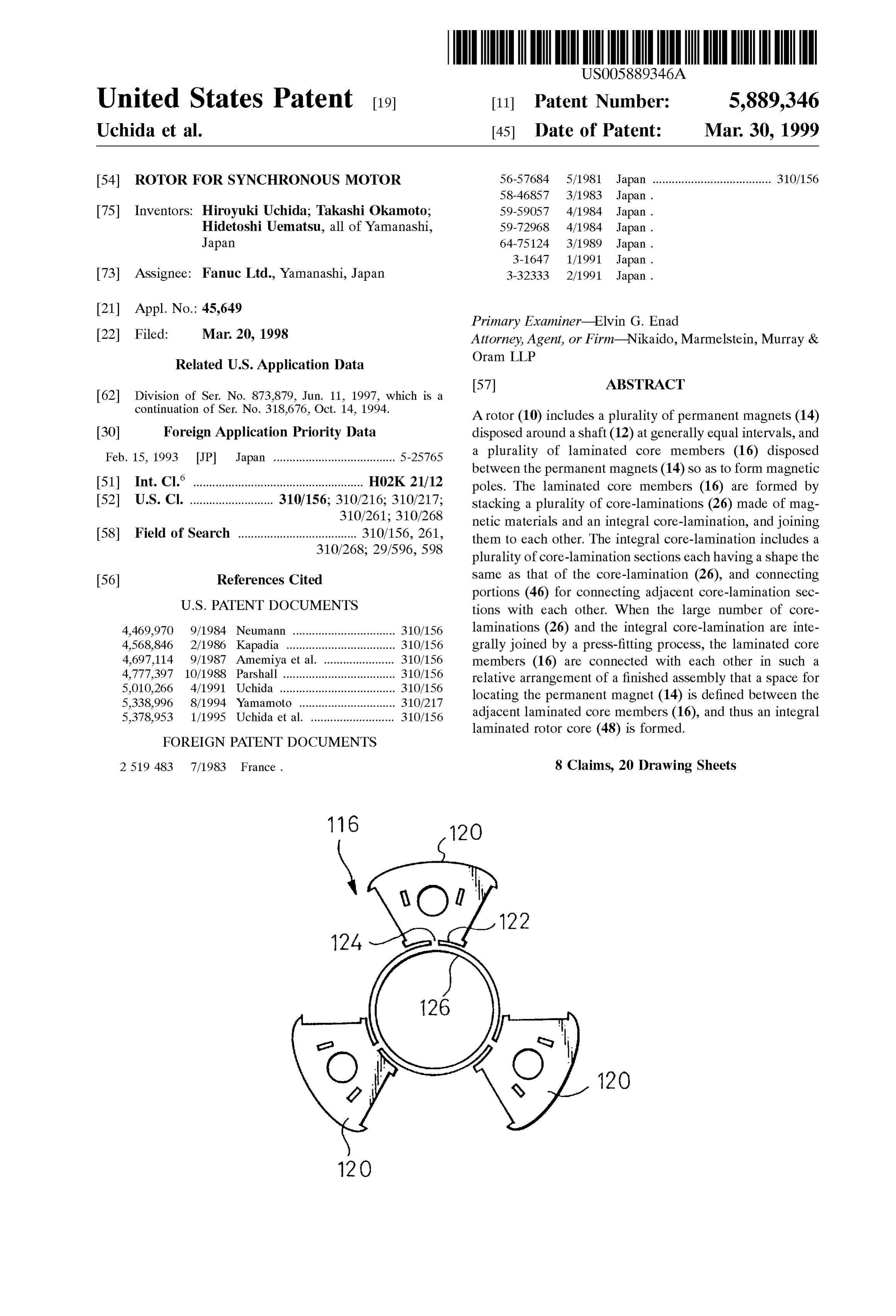
United States Patent (19) 11 Patent Number: 5,889,346 Uchida et al. (45) Date of Patent: Mar. 30, 1999 54) ROTOR FOR SYNCHRONOUS MOTOR 56-57684 5/1981 Japan ..................................... 310/156
75 Inventors: Hiroyuki Uchida; Takashi Okamoto; 59-59057 4/1984 Japan. Hidetoshi Uematsu, all of Yamanashi, 59-72968 4/1984 Japan.
Japan 64-75124 3/1989 Japan.
73 Assignee: Fanuc Ltd., Yamanashi, Japan 3-32333 2/1991 Japan.
Primary Examiner Elvin G. Enad 22 Filed: Mar 20, 1998 Attorney, Agent, or Firm Nikaido, Marmelstein, Murray & Oram LLP
Related U.S. Application Data
continuation of Ser. No. 318,676, Oct. 14, 1994. A rotor (10) includes a plurality of permanent magnets (14) 30 Foreign Application Priority Data disposed around a shaft (12) at generally equal intervals, and Feb. 15, 1993 JP Japan ...................................... 5-25765 a plurality of laminated core members (16) disposed between the permanent magnets (14) So as to form magnetic (51) Int. Cl." ..................................................... HO2K 21/12 poles. The laminated core members (16) are formed by 52 U.S. Cl. .......................... 310/156; 310/216; 310/217; Stacking a plurality of core-laminations (26) made of mag 310/261; 310/268 netic materials and an integral core-lamination, and joining 58 Field of Search ..................................... 310/156, 261, them to each other. The integral core-lamination includes a 310/268; 29/596,598 plurality of core-lamination Sections each having a shape the 56) References Cited same as that of the core-lamination (26), and connecting portions (46) for connecting adjacent core-lamination Sec
4,469,970 9/1984 Neumann ................................ 310/156 laminations (26) and the integral core-lamination are inte 4,568,846 2/1986 Kapadia .................................. 310/156 grally joined by a preSS-fitting process, the laminated core 4,697,114 9/1987 Amemiya et al. ...................... 310/156 members (16) are connected with each other in such a 4,777,397 10/1988 Parshall ................ ... 310/156 relative arrangement of a finished assembly that a Space for 5,010,266 4/1991 Uchida ......... ... 310/156 locating the permanent magnet (14) is defined between the 5,338.996 8/1994 Yamamoto ....... ... 310/217 5,378,953 1/1995 Uchida et al. .......................... 310/156 adjacent laminated core members (16), and thus an integral
FOREIGN PATENT DOCUMENTS
laminated rotor core (48) is formed.
2519 483 7/1983 France. 8 Claims, 20 Drawing Sheets
Page 2
Drawing sheet — no readable text.
Page 3
Drawing sheet — no readable text.
Page 4
Drawing sheet — no readable text.
Page 5
Drawing sheet — no readable text.
Page 6
Drawing sheet — no readable text.
Page 7
Drawing sheet — no readable text.
Page 8
Drawing sheet — no readable text.
Page 9
Drawing sheet — no readable text.
Page 10
Drawing sheet — no readable text.
Page 11
Drawing sheet — no readable text.
Page 12
Drawing sheet — no readable text.
Page 13
Drawing sheet — no readable text.
Page 14
Drawing sheet — no readable text.
Page 15
Drawing sheet — no readable text.
Page 16
Drawing sheet — no readable text.
Page 17
Drawing sheet — no readable text.
Page 18
Drawing sheet — no readable text.
Page 19
A FLAT ROLLED
MAGNETIC STEEL
SHEET
FORMING AN INTEGRAL,
PERIPHERAL CONNECTING
PORTIONS CUT
CUT THE OUTER PERIPHERAL
CONNECTING PORTIONS
ARE INNER
PERIPHERAL CONNECTING
PORTIONS CUT
CUT THE INNER PERIPHERAI,
CONNECTING PORTIONS
STACKING, CAULKING
AN INTEGRAL LAMINATED
ROTOR CORE
Page 20
Drawing sheet — no readable text.
Page 21
Drawing sheet — no readable text.
Page 22
ROTOR FOR SYNCHRONOUS MOTOR laminated core members disposed around a rotating shaft alternately in a circumferential direction, which can facili
This is a Divisional Application of U.S. Ser. No. 08/873, tate positioning or fixing processes of the permanent mag 879, filed Jun. 11, 1997, which is a Continuation of Ser. No. nets and laminated core members in an assembling process 08/318,676, filed Oct. 14, 1994, now abandoned. So as to improve productivity, and also can improve mechanical Strength and thus performance and reliability of
TECHNICAL FIELD a high Speed or high torque motor.
To accomplish the above objects, the present invention
The present invention relates to a rotor for a Synchronous provides a rotor for a Synchronous motor comprising a shaft; motor, which includes a plurality of permanent magnets a plurality of permanent magnets disposed around the shaft disposed around a shaft and magnetized alternately in a at generally equal intervals, a plurality of core members circumferential direction, and a plurality of laminated core disposed around the shaft while holding each of the perma members disposed around the shaft while holding each nent magnets therebetween in a circumferential direction, So permanent magnet therebetween in the circumferential as to form magnetic poles; Supporting means for fixedly direction So as to form magnetic poles. 15
Supporting the permanent magnets and the core members onto the Shaft; and connecting means for fixedly connecting
BACKGROUND ART the core members located at desired positions around the In the field of Synchronous motors, a rotor as mentioned shaft with each other in a relative arrangement of a finished above, which includes permanent magnets magnetized in a rotor assembly.
circumferential direction and laminated core members each In the rotor according to the present invention, the con forming a magnetic pole between the permanent magnets, necting means enables the core members located at desired the magnets and the core members being alternately dis positions already to be integrally handled in a State in which they are relatively positioned. Accordingly, the productivity posed around a shaft, has been used. In this type of con for assembling a rotor is significantly improved, and, after ventional rotor, each laminated core member is generally being assembled, the mechanical Strength of a rotor Structure formed by Stacking a plurality of core-laminations made of 25 is improved because the connecting means assists the Sup magnetic materials. Such as Silicon Steel plates. Each core port of the core members and the permanent lamination may have recesses and projections, which are an external force Such as a centrifugal force.magnets against formed at corresponding positions on respective axial end faces of core-lamination and can be engaged with each other. In a preferred embodiment of the present invention, each The core-laminations can be joined to each other by, e.g., of the core members is a laminated core member formed by preSS-fitting the core-laminations together while aligning the axially Stacking and joining a plurality of core-laminations recesses and projections of the adjacent core-laminations. made of magnetic materials, and the connecting means Each permanent magnet is held between a pair of adjacent comprises at least one integral core-lamination made of a magnetic material, the integral core-lamination including laminated core members and brought into close contact with Sections the Side faces of the latter. The permanent magnet may be 35 which are inserted between the core-laminations of positioned and fixedly Supported in a radial direction by the laminated core members located at the desired positions outer and inner hooks protruding from the Side faces of each and are joined to adjacent core-laminations. In this case, the laminated core member at Outer and inner peripheral regions integral core-lamination may include core-lamination Sec tions having shapes generally the same as those of the thereof. A rod member may be inserted into an axial through core-laminations of the laminated core members and the hole formed generally at the center of each laminated core 40 number thereof member. Each rod member may be connected to annular end poles So as to be inserted being the same as the number of magnetic plates which are arranged at both axial ends of the laminated and joined between the core core member and fixed to the rotating shaft. In this manner, laminations, and also include connecting portions extended the laminated core members and the permanent magnets are from the core-lamination Sections So as to annularly connect fixedly held in the rotor against external force Such as 45 all of the core-lamination Sections in a predetermined centrifugal force, by the end plates, the rod members and the arrangement, whereby all of the core-lamination Sections are hookS. connected in Such a relative arrangement of a finished rotor assembly that a Space for locating each permanent magnet is
This type of rotor uses a plurality of permanent magnets defined and laminated core members, the number of which corre between adjacent core-lamination Sections, So as to sponds to the number of magnetic poles, therefore it has 50 form an integral laminated rotor core. Alternatively, the problems in that the work of positioning or fixing the integral tions core-lamination may include core-lamination Sec having shapes being generally the same as those of the permanent magnets and laminated core members is core-laminations of the laminated core members and the complicated, increased working time and Skilled workers are number thereof being half the number of magnetic poles So required, and thus improvement of perSonnel requirements as to be inserted and joined between the core-laminations, and productivity is prevented. Further, the accuracy of 55 and connecting portions extended from the core-lamination positioning the permanent magnets and laminated core Sections members depends on the mechanical Strength and proceSS Sections So as to annularly connect all of the core-lamination ing accuracy of the rod members and end plates. laminatedincore a predetermined arrangement, whereby all of the members forming the same magnetic poles
Consequently, in the case of high Speed motorS or high are fixedly connected torque motors, additional means for improving the mechani 60 finished rotor assemblyinthat Such a relative arrangement of a a Space for locating one lami cal Strength of the whole Structure of the rotor is required in nated core member forming another magnetic pole and two order to accurately hold the permanent magnets and lami permanent magnets is defined between adjacent core nated core members in predetermined positions. lamination Sections.
DISCLOSURE OF THE INVENTION 65 BRIEF DESCRIPTION OF THE DRAWINGS An object of the preset invention is to provide a rotor for The foregoing and the other objects, features, and advan a Synchronous motor including permanent magnets and tages of the present invention will be described with refer
Page 23
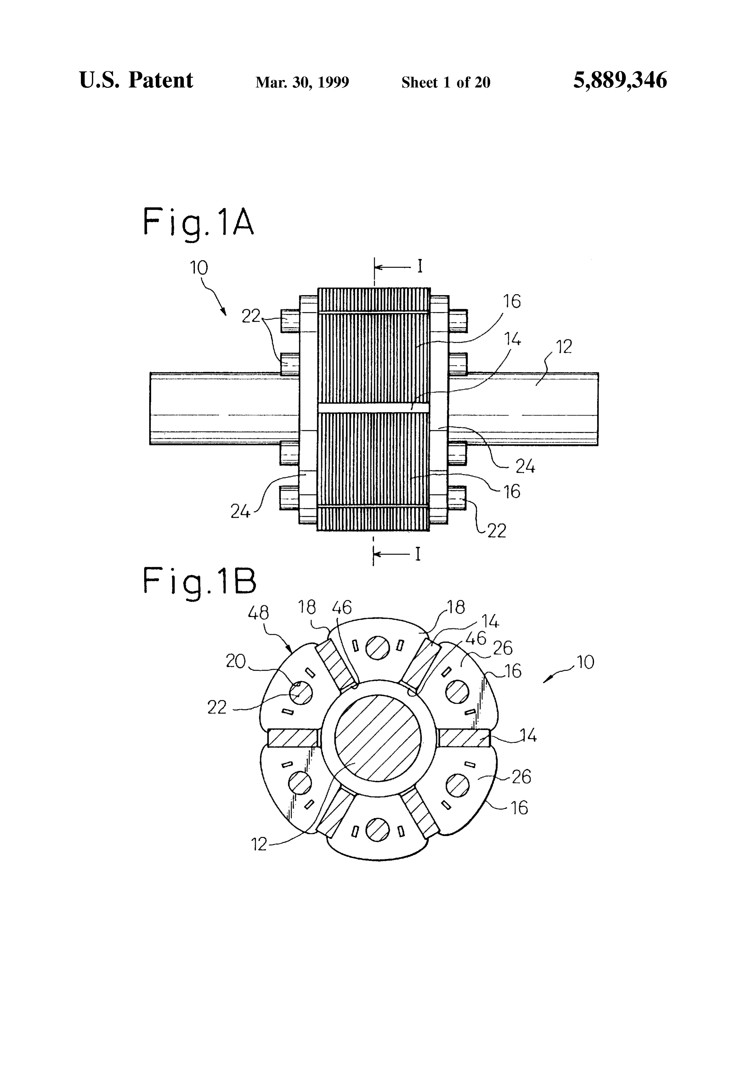
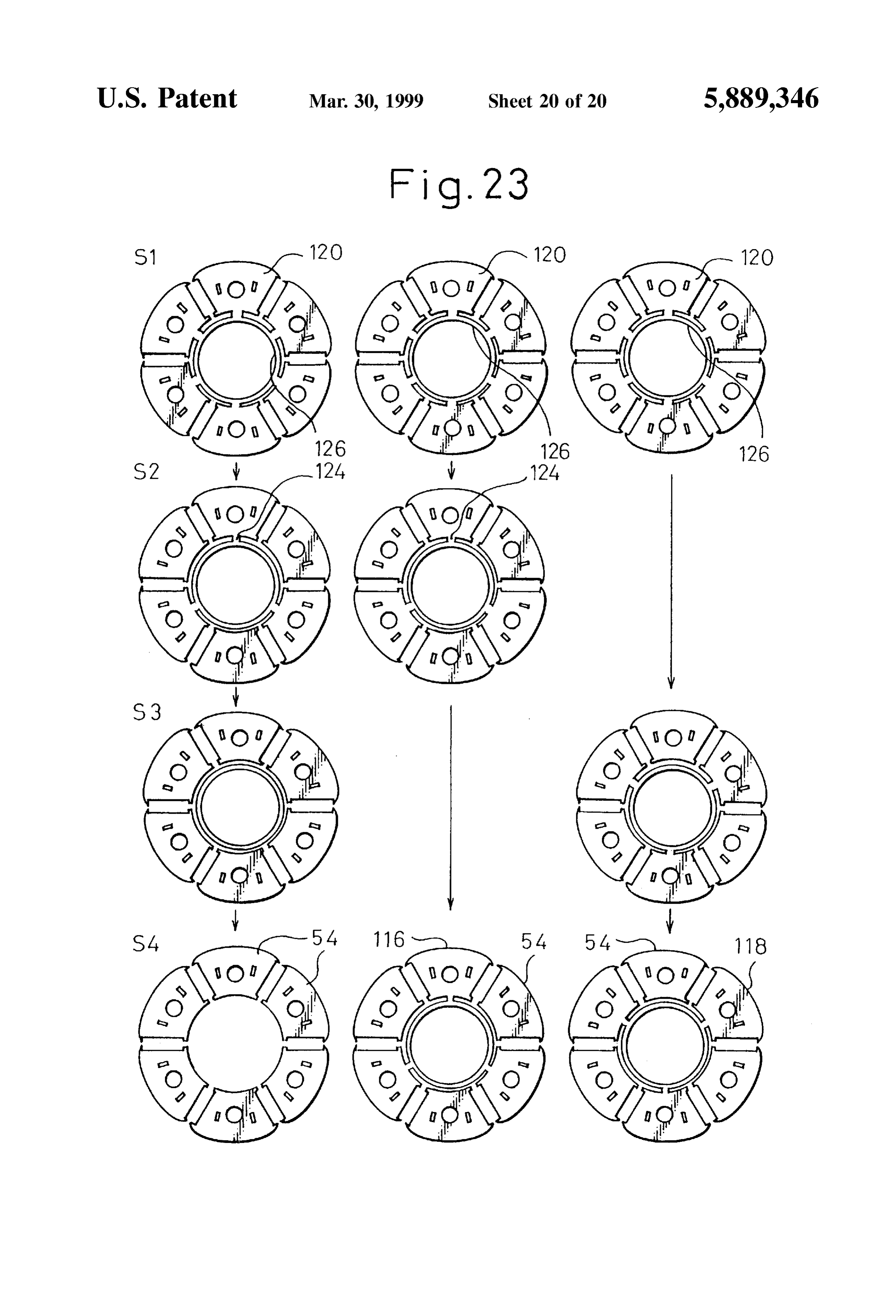
ence to the embodiments shown in the accompanying FIG. 22 is an illustration of stamped products formed at drawings, in which, respective Steps according to the manufacturing process FIG. 1A is a Side view of a rotor according to an shown in FIG. 21; and embodiment 1 of the present invention; FIG. 23 is an illustration showing a manufacturing pro FIG. 1B is a sectional view taken along line I-I of FIG. cess of the integral laminated rotor core shown in FIG. 14 by 1A; Stamped products formed at respective Steps thereof. FIG. 2A is a perspective view of an integral laminated BEST MODE OF CARRYING OUT THE rotor core of the rotor shown in FIG. 1A; INVENTION
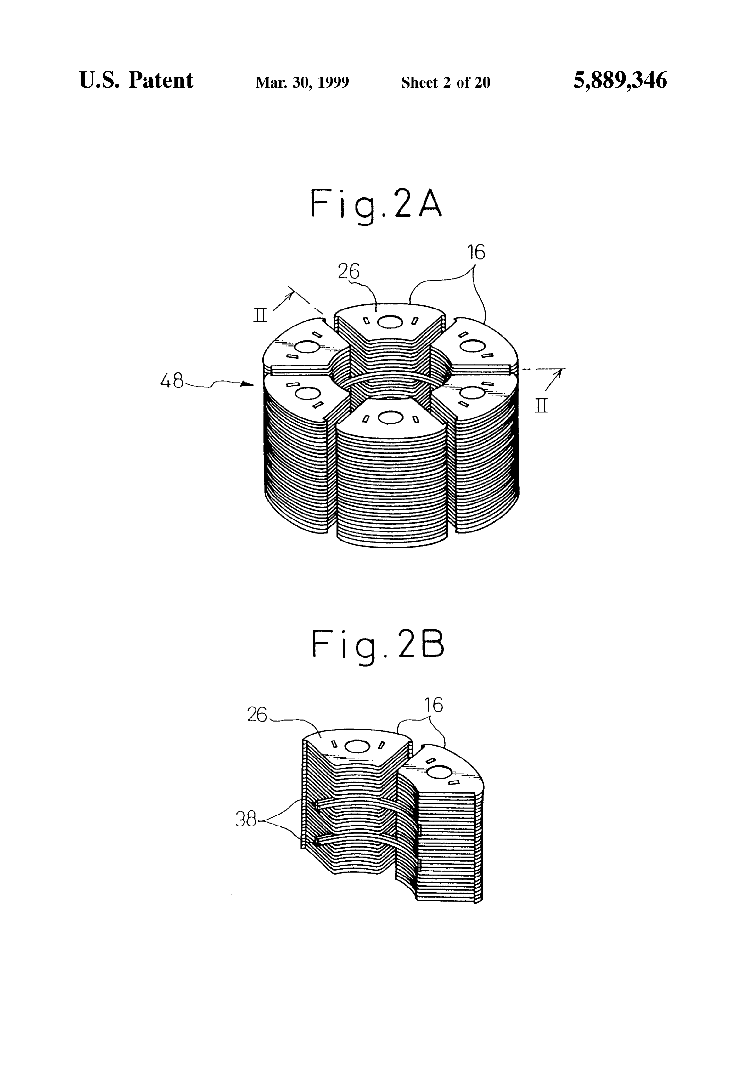
FIG. 2B is a perspective view of a part taken along line 1O In the following description of embodiments, the same or II-II of FIG. 2A; Similar components are represented by the same reference FIG. 3A is a plan view of a core-lamination of the integral numerals.
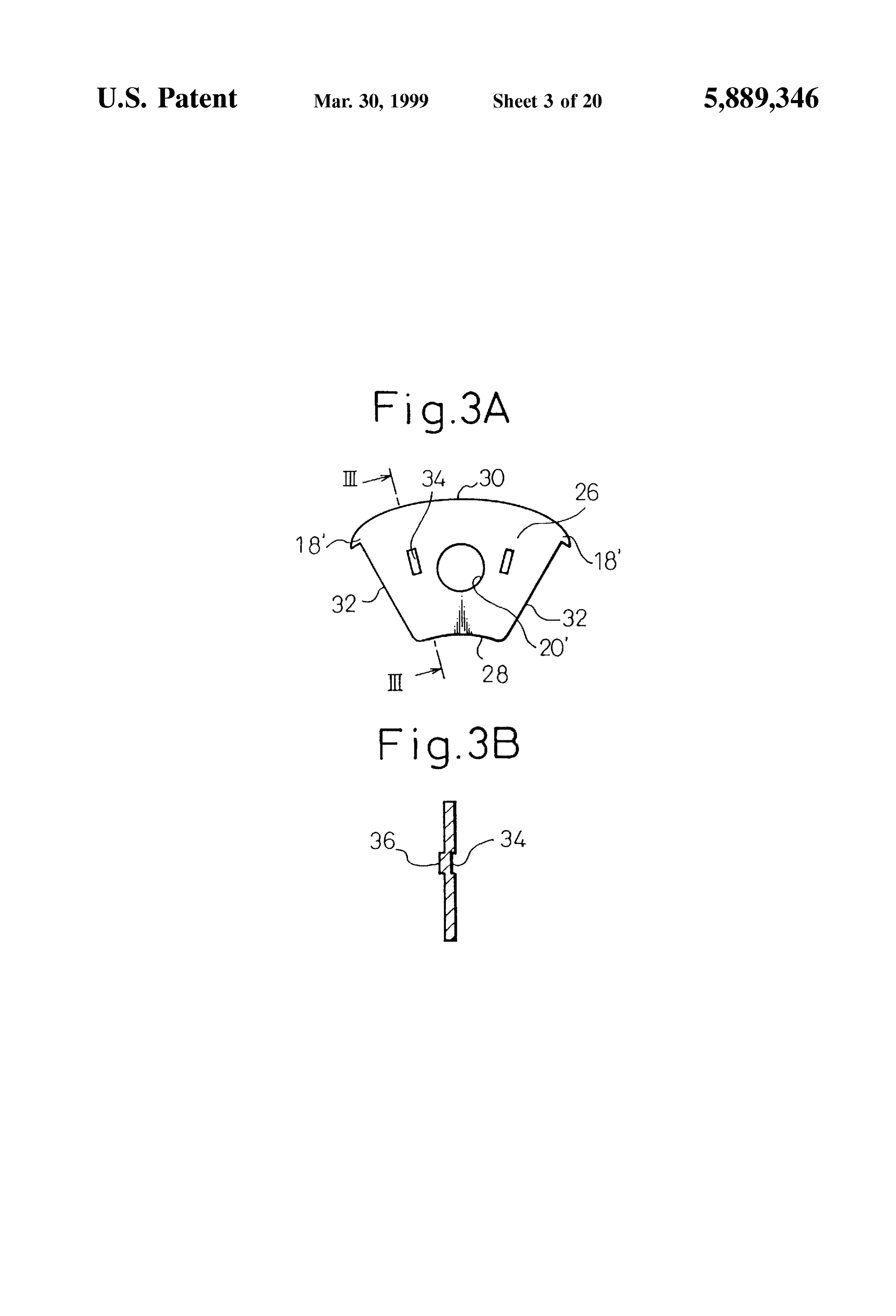
laminated rotor core shown in FIG. 2A, Embodiment 1
FIG. 3B is a sectional view taken along line III-III of Referring to the drawings, FIGS. 1A and 1B show a rotor FIG. 3A; 15 10 for a synchronous motor according to the embodiment 1
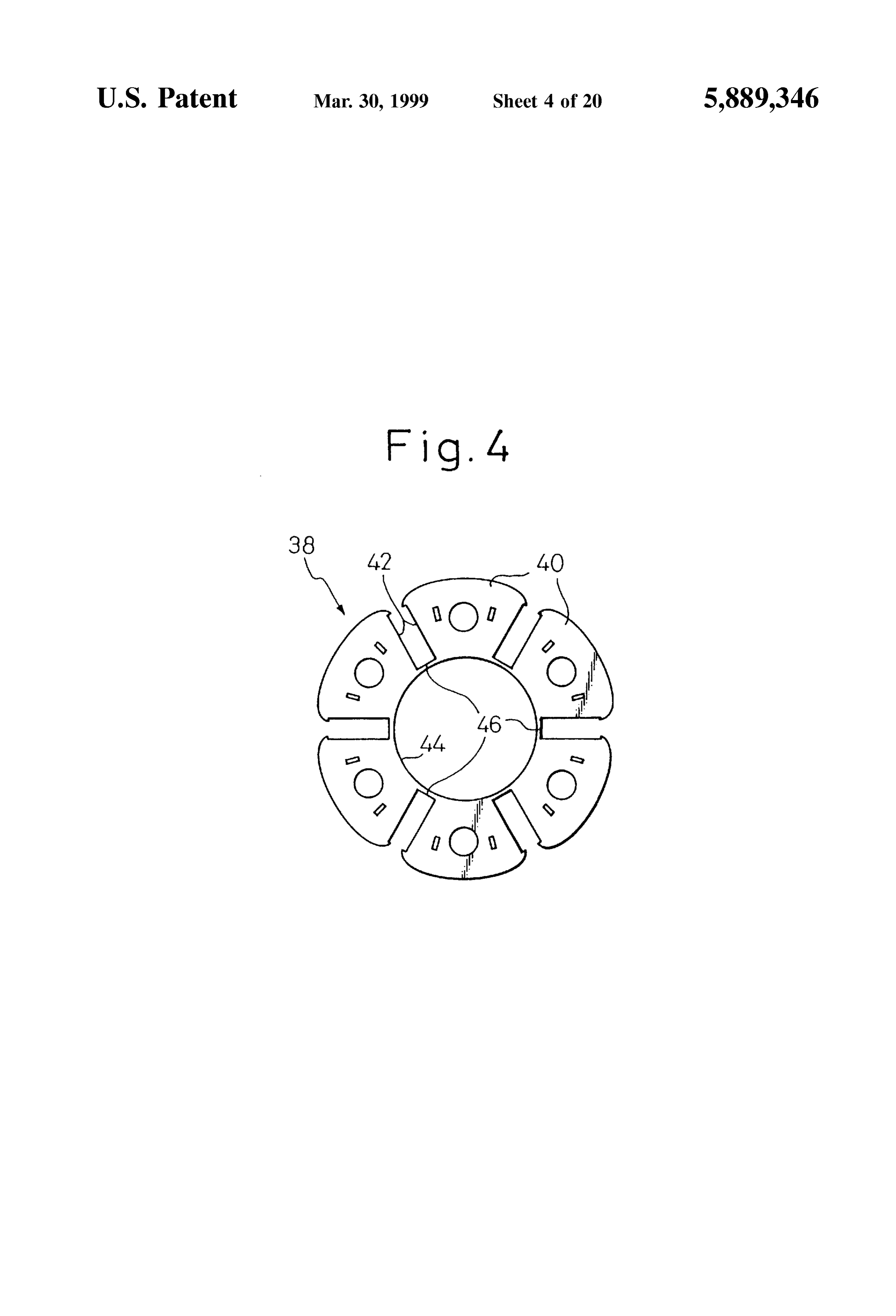
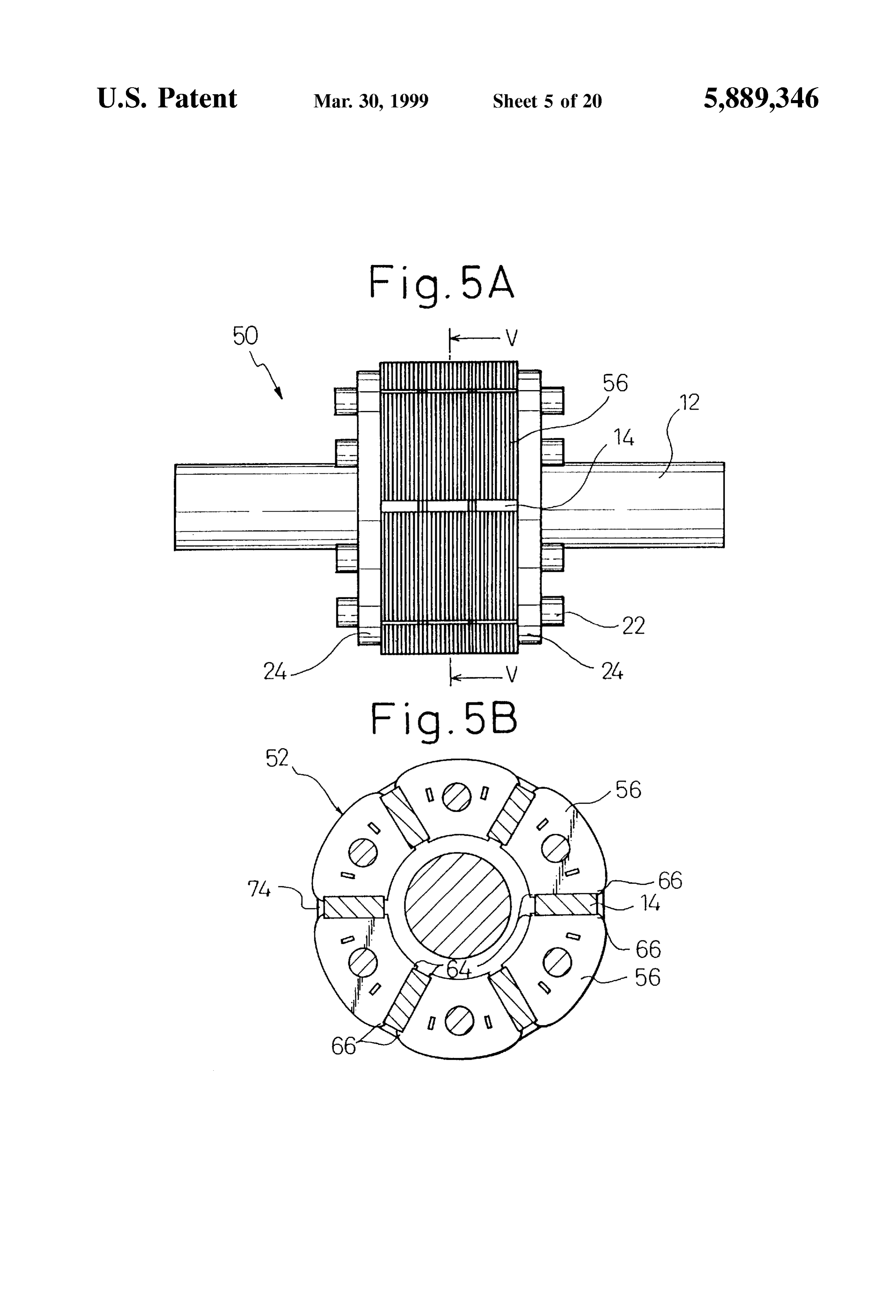
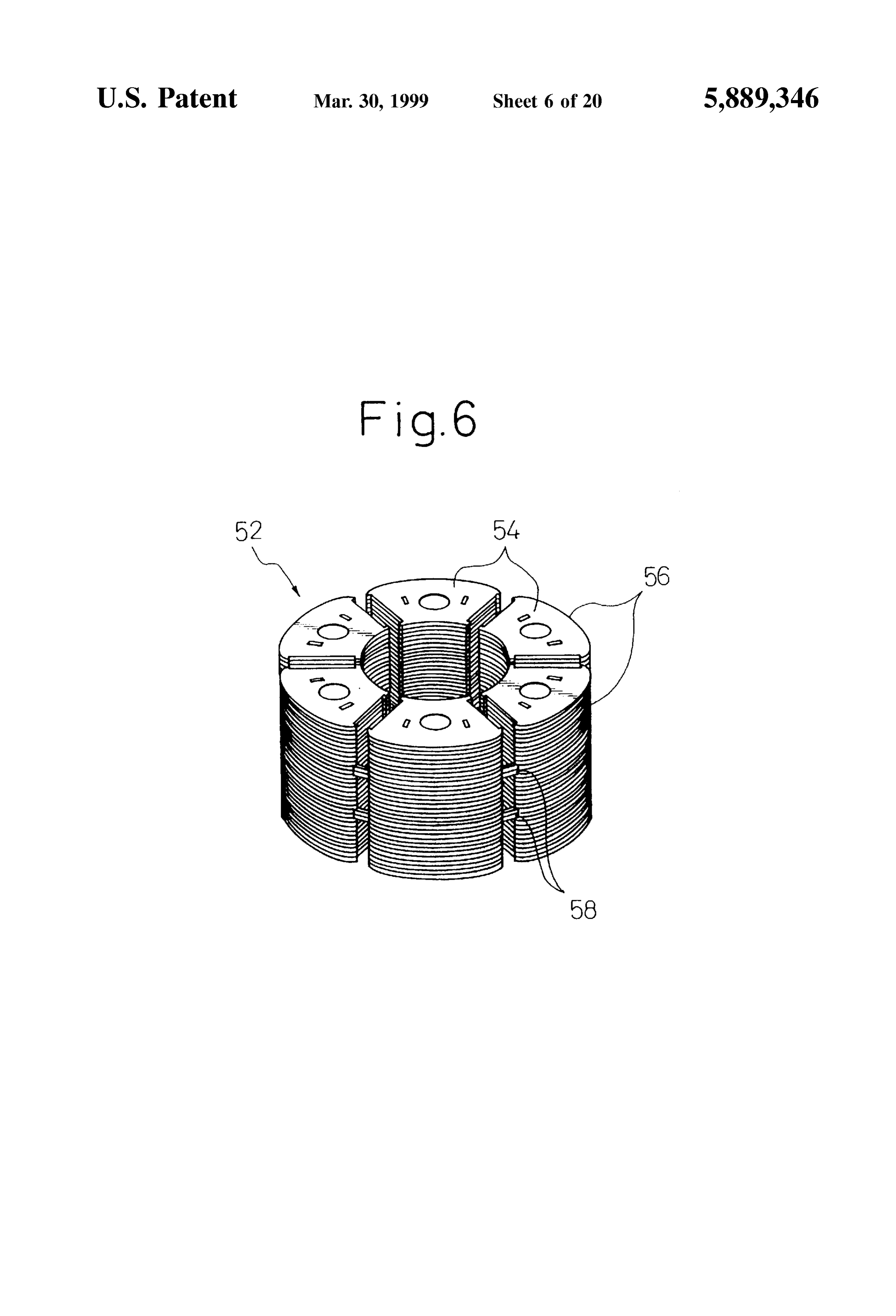
FIG. 4 is a plan view of an integral core-lamination of the of the present invention. The rotor 10 includes a shaft 12, a integral laminated rotor core shown in FIG. 2A, plurality (six in this embodiment) of permanent magnets 14 FIG. 5A is a side view of a rotor according to an disposed around the Shaft 12 at generally equal intervals and embodiment 2 of the present invention; magnetized alternately in a circumferential direction, and a FIG. 5B is a sectional view taken along line V-V of FIG. plurality (six in this embodiment) of laminated core mem 5A; bers 16 disposed around the shaft 12 while holding each FIG. 6 is a perspective view of an integral laminated rotor permanent magnet 14 therebetween in the circumferential core of the rotor shown in FIG. 5A; direction So as to form magnetic poles. Each permanent 25 magnet 14 is held between and brought into close contact
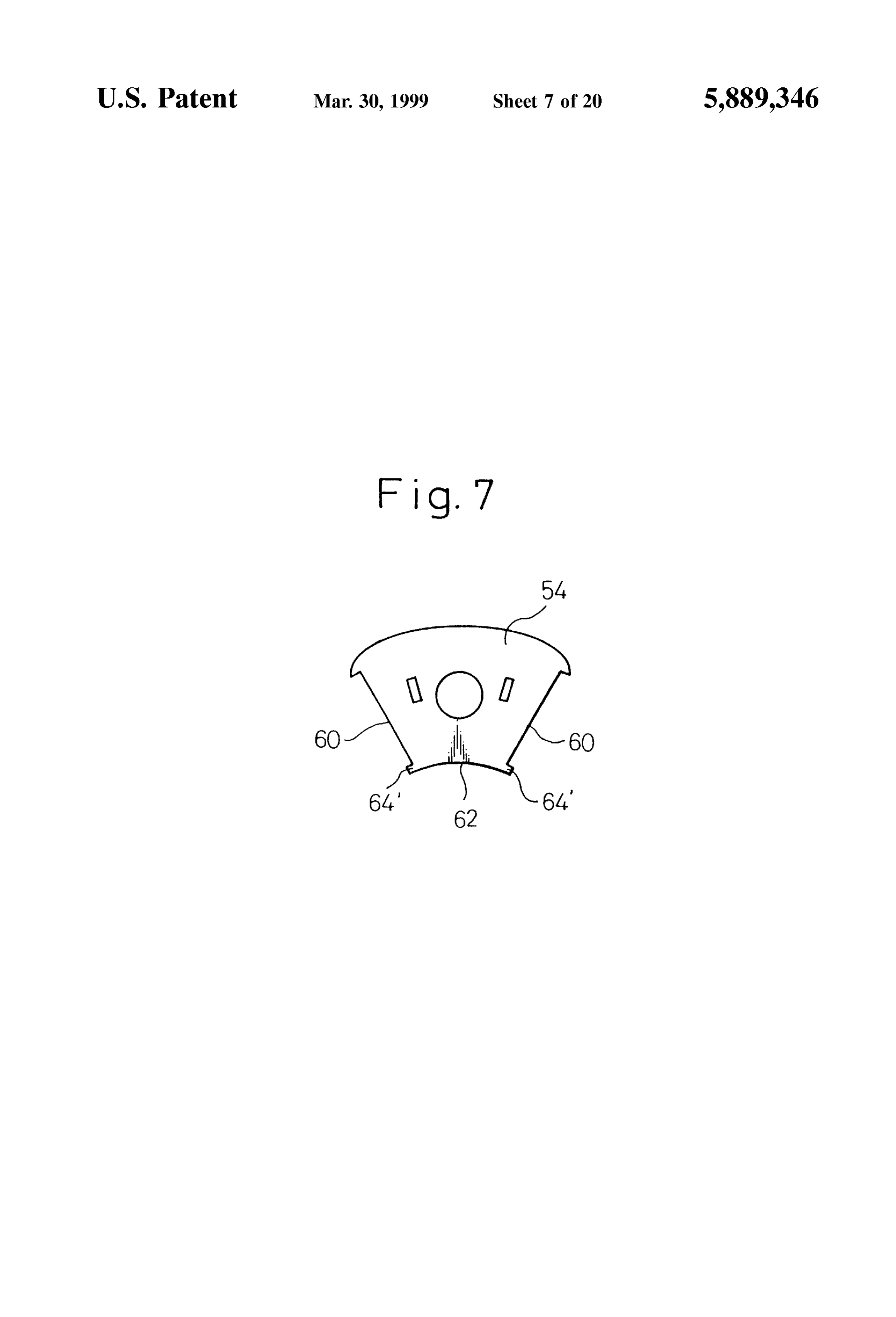
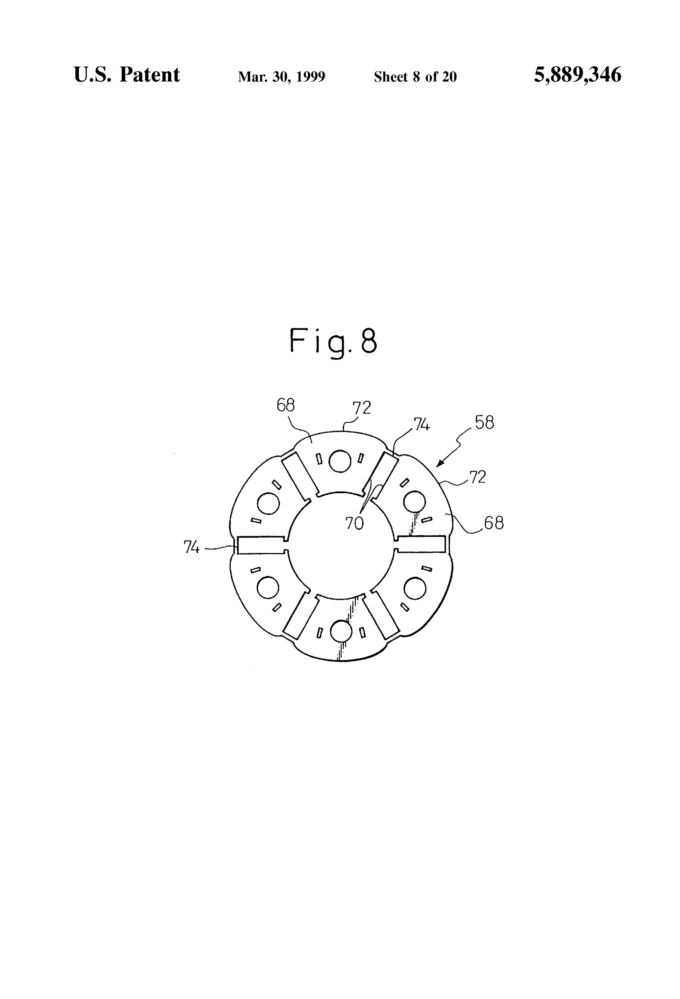
FIG. 7 is a plan view of a core-lamination of the integral with laminated rotor core shown in FIG. 6; the Side faces of adjacent laminated core members 16. Each laminated core member 16 includes outer hooks 18
FIG. 8 is a plan view of an integral core-lamination of the protruding from both side faces at Outer peripheral regions integral laminated rotor core shown in FIG. 6; thereof. Therefore, each permanent magnet 14 is positioned FIG. 9 is a plan view of an integral core-lamination of a in a radial direction by the outer hook 18 of the laminated rotor according to an embodiment 3 of the present invention; core member 16 and fixedly Supported against centrifugal FIG. 10 is a perspective view of an integral laminated force. The laminated core members 16 are respectively rotor core using the integral core-lamination shown in FIG. provided with rod holes 20 axially penetrating through the 9; generally center portions of the core members, and rod FIG. 11A is a perspective View of an integral laminated 35 members 22 are inserted into respective rod holes 20. These rotor core of a rotor according to an embodiment 4 of the rod members 22 are connected to a pair of annular end plates present invention; 24 arranged at both axial ends of the laminated core mem FIG. 11B is a schematic view of a laminated construction bers 16. Each end plate 24 is fixed to the shaft 12 by shrink fitting or bonding.
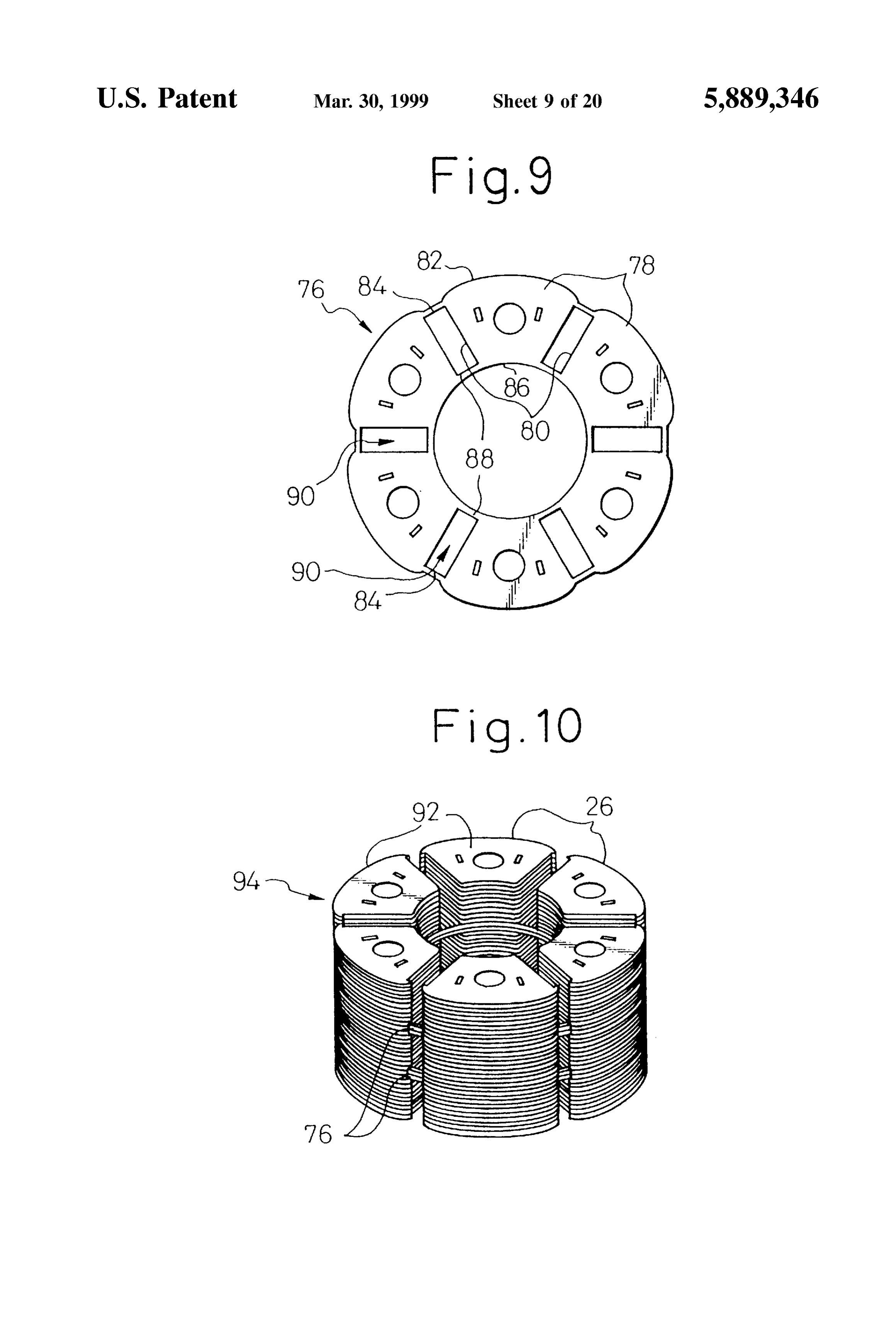
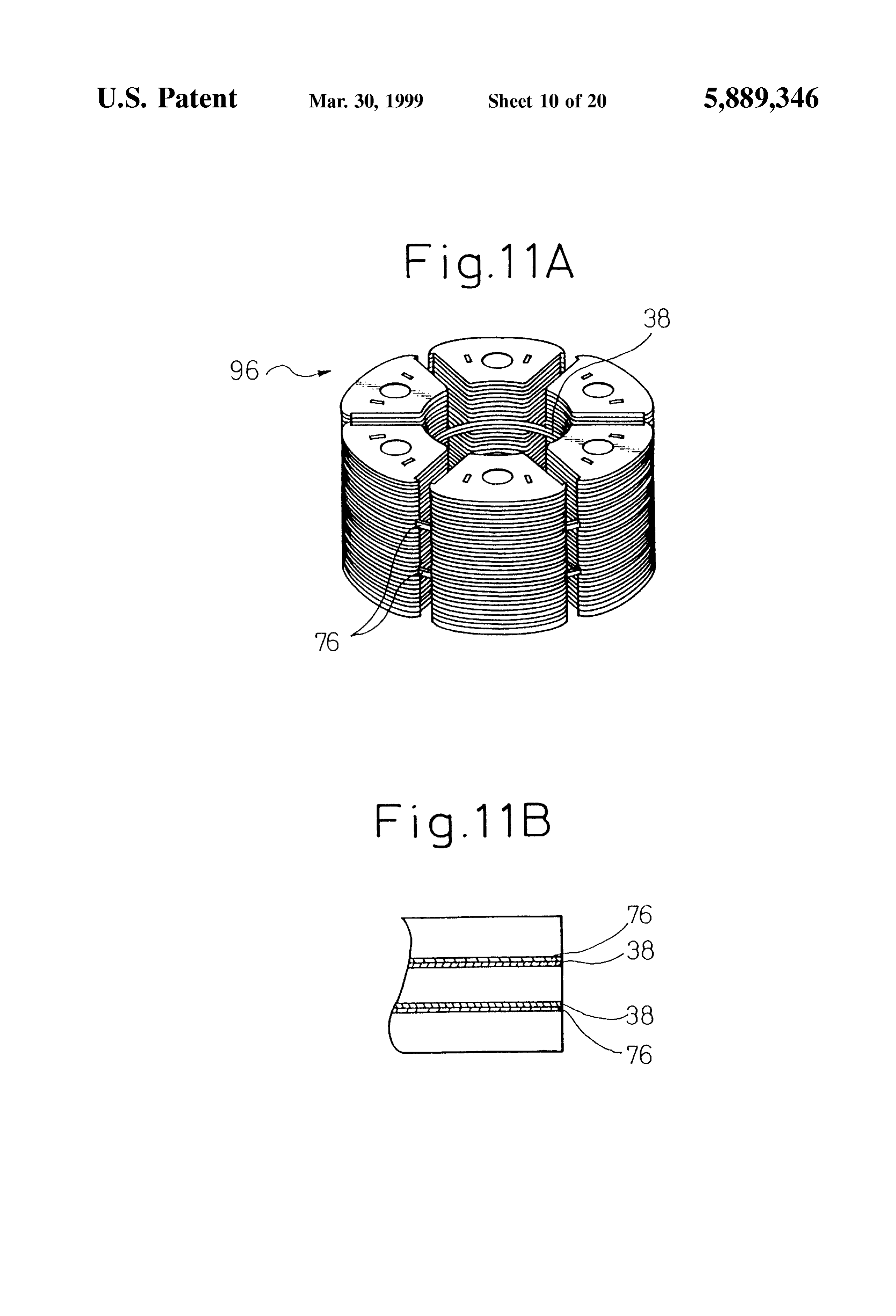
of the integral laminated rotor core shown in FIG. 11A;
As shown in FIGS. 2A and 2B, the laminated core
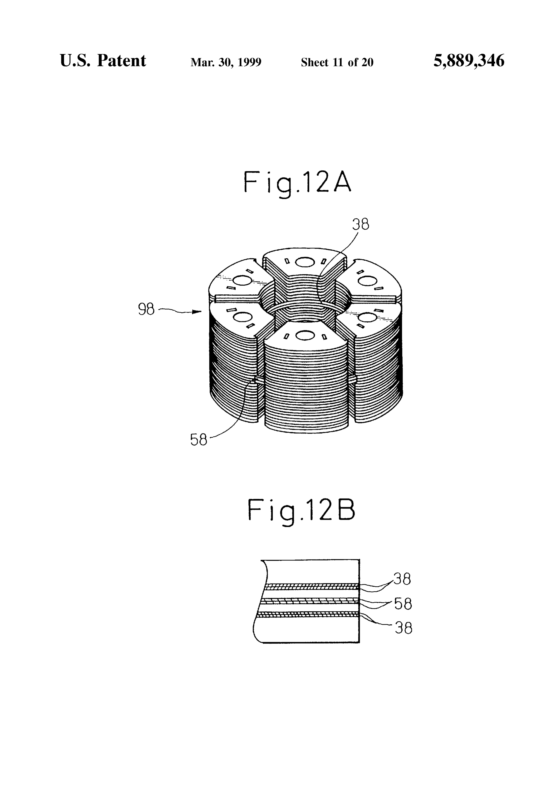
FIG. 12A is a perspective view of an integral laminated 40 members rotor core of a rotor according to an embodiment 5 of the formed 16 forming six magnetic poles of the rotor 10 are present invention; by Stacking a plurality of core-laminations 26 made FIG. 12B is a schematic view of a laminated construction of magnetic materials. Such as Silicon Steel plates and joining them to each other. As more clearly shown in FIGS. 3A and of the integral laminated rotor core shown in FIG. 12A; 45 3B, the core-lamination 26 has a generally Sector shape in a FIG. 13 is a plan view of an integral core-lamination of a plan view, which includes an arcuate inner edge 28 adapted rotor according to an embodiment 6 of the present invention; to surround the shaft 12, an outer edge 30 with a predeter FIG. 14 is a Sectional view of a rotor according to an mined curved-out shape adapted to be opposed to a Stator embodiment 7 of the present invention; (not shown), and both sides 32 adapted to be brought into FIGS. 15A and 15B are plan views of integral core 50 contact with the permanent magnet 14. The core-lamination laminations of a rotor shown in FIG. 14; 26 is provided at both sides 32 thereof with outer hook FIG. 16A is a perspective view of two integral laminated elements 18' extended from the outer edge 30, and at the rotor cores of the rotor shown in FIG. 14, center thereof with a rod hole element 20'. When the FIG. 16B is a perspective view of a part taken along line core-laminations 26 are Stacked in an exactly Superimposed XVI-XVI of FIG. 16A; 55 manner, the outer hook elements 18' and the rod hole FIG. 17 is a plan view of a modification of a core elementsand the 20' are axially joined and form the outer hook 18 rod hole 20. The core-lamination 26 is provided on lamination of the integral laminated rotor core shown in respective axial end faces thereof with a receSS 34 and a FIG. 16; projection 36 formed at a corresponding position, the pro FIG. 18 is a sectional view of a rotor according to an 60 jection being able to be fitted into the receSS. The core embodiment 8 of the preset invention; laminations 26 are Stacked in Such a manner that the receSS FIGS. 19A and 19B are plan views of integral core 34 and the projection 36 of the adjacent core-laminations 26 laminations of a rotor shown in FIG. 18; are aligned with each other, and after that the core FIG. 20 is a sectional view of a rotor according to an laminations 26 are joined together by a press-fitting process embodiment 9 of the present invention; 65 using, e.g., a press machine (not shown). FIG. 21 is a flow chart showing a manufacturing proceSS As shown in FIGS. 2A and 2B, a plurality of integral of the integral laminated rotor core shown in FIG. 11A; core-laminations 38 are inserted or arranged at predeter
Page 24
S 6 mined positions in a laminated construction formed by the whereby the productivity is remarkably improved in the core-laminations 26 of each laminated core member 16. AS Subsequent Step of fitting to the shaft 12. shown in FIG. 4, the integral core-lamination 38 includes six Embodiment 2 core-lamination Sections 40 each having the Same shape as FIGS. 5A and 5B show a rotor 50 according to an the core-lamination 26. Each core-lamination Section 40 is 5
Stacked and joined together with the large number of core embodiment 2 of the present invention. The rotor 50 laminations 26 in the above-mentioned manner to form the includes an integral laminated rotor core 52 which has a laminated core member 16. The core-lamination section 40 structure similar to the integral laminated rotor core 48 of the includes connecting portions 46 extended in the circumfer embodiment 1. As shown in FIG. 6, the integral laminated ential direction from both sides 42 at an inner edge 44 of the rotor core 52 includes a plurality of laminated core members core-lamination Section. The core-lamination Sections 40 are 56 which are formed by Stacking and joining the large mutually connected through the connecting portions 46 in number of core-laminations 54. These laminated core mem Such a relative arrangement that a Space for locating the berS 56 are connected together by integral core-laminations permanent magnet 14 is defined between the adjacent core 58 which are inserted into the predetermined positions in the lamination Sections 40. In this manner, the integral core 15 laminated Structure of the core-laminations 54 and joined lamination 38, of which all core-lamination sections 40 are together with the latter. As shown in FIG. 7, the core annularly connected, is formed. lamination 54 has Substantially the same shape as the In the illustrated embodiment, four integral core core-lamination 26 of the embodiment 1, except that inner laminations 38 are arranged at two positions dividing the hooks 64' are extended in a circumferential direction from laminated length of the core-laminations 26 of each lami both sides 60 at an inner edge 62. The inner hooks 64 form nated core member 16 into three generally equal parts, two inner hooks 64 of the laminated core member 56 by stacking a plurality of core-laminations 54. The inner hooks 64 integral core-laminations being arranged at each of the two cooperate positions. When the large number of core-laminations 26 Support thewith outer hookS 66 So as to position and fixedly permanent magnet 14.
and the four integral core-laminations 38, which are arranged in this manner, are joined together by a preSS-fitting 25 As shown in FIG. 6, two integral core-laminations 58 are process, the laminated core members 16 are mutually con arranged at two positions dividing the laminated length of nected in Such a relative arrangement of a finished assembly each laminated core member 56 into three generally equal that a Space for locating the permanent magnet 14 is defined parts, in the same manner as the embodiment 1. Of course, between the adjacent laminated core members 16 as shown other numbers or arrangements of the integral core in FIG. 1B, whereby an integral laminated rotor core 48 is laminations 58 may be adopted. As shown in FIG. 8, the formed (see FIG. 2A). It should be noted that a different integral core-lamination 58 includes a plurality of core number of the integral core-laminations 38 may be provided lamination Sections 68 each having the same shape as the other than the above-mentioned number, but preferably a core-lamination 54. Each core-lamination section 68 is Small number are provided as long as the mechanical Stacked and joined together with the large number of core Strength of the connecting Structure between the laminated 35 laminations 54 So as to form the laminated core member 56. core members can be maintained, from the Viewpoint of the 74 The core-lamination Section 68 includes connecting portions reduction of magnetic leakage. Also, the integral core extended in the circumferential direction from both sides laminations 38 may have various arrangements in the lami 70 at an outer edge 72 of the core-lamination section. The nated Structure other than the above-mentioned core-lamination Sections 68 are mutually connected through arrangement, but preferably have a regular and Symmetrical 40 the connecting portions 74 in Such a relative arrangement arrangement in order to obtain an entirely balanced Strength. that a Space for locating the permanent magnet 14 is defined The connecting poritons 46 of the integral core between the adjacent core-lamination Sections 68. lamination 38 are formed relatively thin as long as the In the rotor 50 including the integral core-laminations 58, mechanical Strength can be maintained, in order to prevent the connecting portions 74 for forming the integral lami magnetic leakage as much as possible. AS shown in FIG. 1B, 45 nated rotor core 52 are provided on the Outer peripheral edge in the integral laminated rotor core 48, the connecting region adapted to be opposed to a Stator, therefore the portions 46 of the integral core-lamination 38 are abutted magnetic leakage performance and the influence for mag onto the inner Surfaces of the permanent magnets 14, which netic flux distribution in an air-gap between the Stator and are opposed to the shaft 12, and cooperate with the outer rotor are inferior to Some extent to the embodiment 1. hooks 18 of the laminated core members 16 so as to position 50 However, the connecting portions 74 reinforce the Support and fixedly Support the permanent magnets 14. of the permanent magnets against an external force Such as Consequently, the laminated core members 16 do not require a centrifugal force, and thereby improve the mechanical inner hooks as used in a conventional Structure, and the Strength of the rotor Structure. magnetic leakage caused by the inner hooks can be elimi Embodiment 3 nated. Thus, it has been observed that the magnetic leakage 55 The rotor according to the present invention may use an in the integral laminated rotor core 48 is, as a whole, about integral core-lamination 76 as shown in FIG. 9, in order to the same as that in the conventional Structure. form an integral laminated rotor core. The integral core The integral laminated rotor core 48 having the above lamination 76 includes a plurality of core-lamination Sec mentioned Structure makes it possible to integrally handle tions 78 which have substantially the same shape as the the laminated core members 16 with the same number (six 60 core-lamination 26 of the embodiment 1. Each core in this embodiment) as the number of magnetic poles in a lamination Section 78 includes outer peripheral connecting State in which they are previously positioned relative to each portions 84 extended in the circumferential direction from other. Accordingly, in the assembling process of the rotor 10, both sides 80 at an outer edge 82 and inner peripheral the permanent magnets 14 can be held between the lami connecting portions 88 extended in the circumferential nated core members 16 merely by inserting and fitting the 65 direction from both sides 80 at an inner edge 86. The permanent magnets 14 into the Spaces for locating perma core-lamination Sections 78 are mutually connected through nent magnets defined in the integral laminated rotor core 48, the outer and inner peripheral connecting portions 84 and 88
Page 25
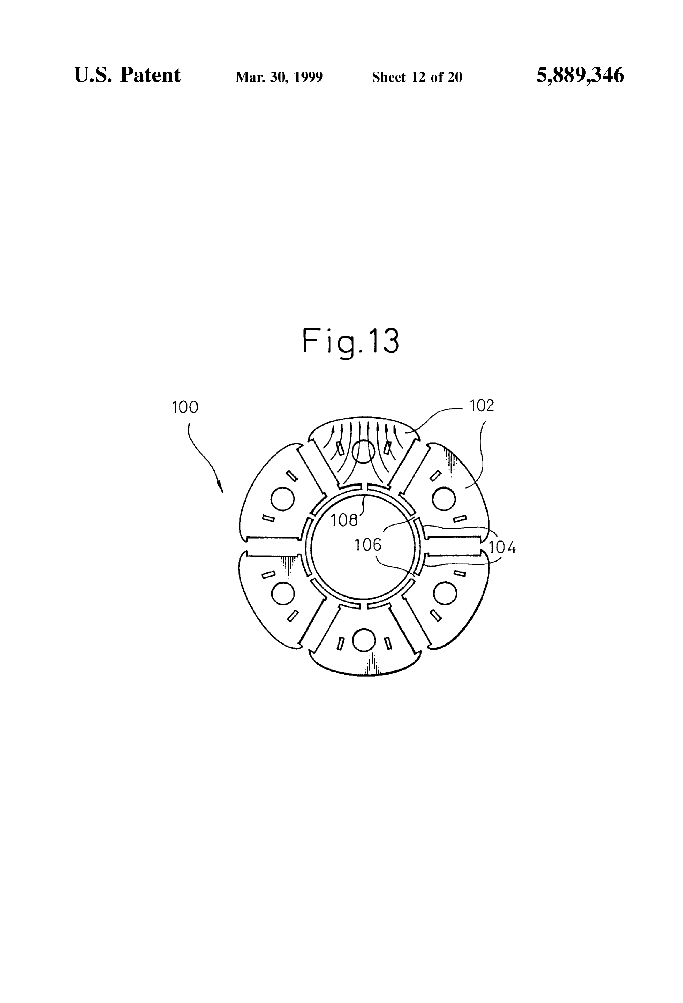
in Such a relative arrangement that a Space 90 for locating a In the case of using the integral core-laminations 100 of permanent magnet is defined between the adjacent core the embodiment 6 in place of the integral core-laminations lamination sections 78. 58 in the integral laminated rotor core 52 of the embodiment Each core-lamination section 78 of the integral core 2, the magnetic leakage through the first connecting portions lamination 76 is stacked and joined with the core 106 and the annular connecting portion 108 is extremely laminations 26 of the embodiment 1. An integral laminated reduced, because the first connecting portions 106 are dis rotor core 94 as shown in FIG. 10 is formed in this manner, posed at the region having low magnetic flux density from which includes a plurality of laminated core members 92 the Viewpoint of magnetic flux flow (shown as arrows in connected to each other. In the case of using the integral FIG. 13) when the permanent magnets 14 are assembled in core-lamination 76, the magnetic leakage performance and the integral laminated rotor core 52. The effect of this the influence on magnetic flux distribution in an air-gap are embodiment on preventing magnetic leakage is extremely inferior to Some extent to the embodiment 1, because the Superior in comparison with the effect of the embodiment 1. Structure has the Outer peripheral connecting portions 84.It is noted that a plurality of first connecting portions 106 However, the mechanical Strength of the integral laminatedmay be extended in parallel from the general center region rotor core 94 is more stable than that of both the above embodiments. Also, the productivity for assembling the 15 of the inner edge 104 of the core-lamination section 102 to rotor is better than both of the above embodiments. Such an extent that the magnetic leakage is not increased. In Embodiment 4 this case, the stiffness of the laminated core member 56 An integral laminated rotor core 96 as shown in FIG. 11A (FIG. 6) against revolution about the first connecting portion 106 is increased.
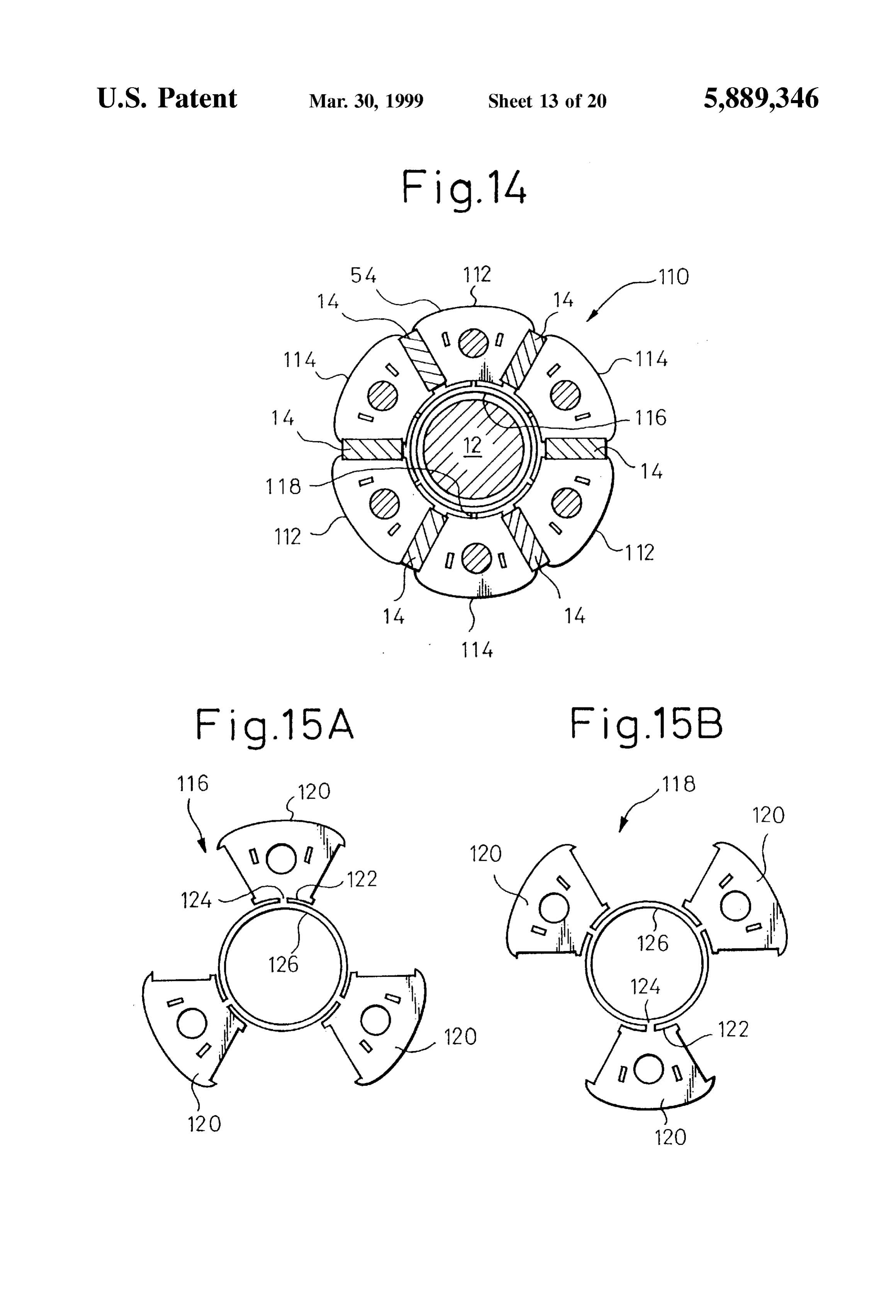
is formed by replacing two of four integral core-laminations 38 of the inner periphery connecting type (FIG. 4), in the Embodiment 7 integral laminated rotor core 48 of the embodiment 1, with In the above-mentioned embodiments, there is a problem the integral core-laminations 76 of the inner and outer as to how the magnetic leakage can be inhibited, which is peripheries connecting type (FIG. 9). From the viewpoint of caused by the connecting portions of the integral core rotor balance, it is preferred that one integral core lamination used for forming the integral laminated rotor lamination 38 is directly Superimposed on one integral 25 core. In this respect, by integrating only the laminated core core-lamination 76 as shown in FIG. 11B and they are members of the same pole instead of integrating all lami arranged at two positions that divide the laminated length of nated core members of the rotor, the magnetic leakage can rotor into three generally equal parts. The integral laminated be substantially eliminated.
rotor core 96 has a mechanical Strength greater than that of the integral laminated rotor core 48 of the embodiment 1 and A rotor 110 as shown in FIG. 14 includes a plurality of a magnetic performance Superior to that of the integral laminated core members 112, 114, both being formed by laminated rotor core 94 of the embodiment 3. Stacking the large number of core-laminations 54, in the Embodiment 5 Same manner as the embodiment 2. The laminated core An integral laminated rotor core 98 as shown in FIG. 12A members 112 and 114 are alternately magnetized by the is formed by adding two integral core-laminations 58 of the 35 permanent magnets 14. In the illustrated embodiment, three outer periphery connecting type (FIG. 8) to the integral laminated core members 112 establishing N-poles are mutu laminated rotor core 48 of the embodiment 1, which includes ally connected through first integral core-laminations 116 four integral core-laminations 38 of the inner periphery which are inserted and joined to the predetermined positions connecting type (FIG. 4). In the illustrated embodiment, in a laminated Structure, and three laminated core members from the Viewpoint of rotor balance, two mutually Superim 40 114 establishing S-poles are mutually connected through posed integral core-laminations 58 are arranged at a gener Second integral core-laminations 118 which are inserted and ally center position between the positions of the two integral joined to the predetermined positions in a laminated Struc ture.
core-laminations 38 as shown in FIG. 2B (see FIG. 12B).
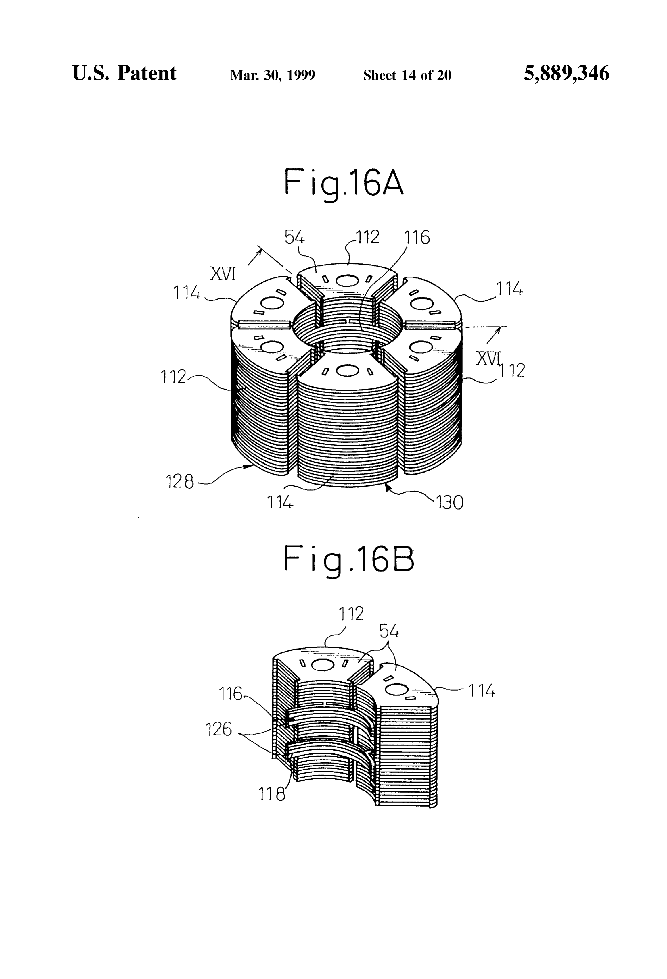
The integral laminated rotor core 98 has a mechanical As shown in FIGS. 15A and 15B, the first integral Strength and a magnetic performance generally equal to 45 core-lamination 116 has the same Structure as the Second those of the integral laminated rotor core 96 of the embodi integral core-lamination 118, and both include three core ment 4. lamination Sections 120 each having the same shape as the Embodiment 6 core-lamination 54. Each core-lamination section 120 FIG. 13 shows an integral core-lamination 100 with a includes a first connecting portion 124 extended in a radially different shape, used to form an integral laminated rotor core 50 inward direction from a generally center of an inner edge according to the present invention. The integral core 122 of the core-lamination Section, and is Supported by an lamination 100 includes a plurality of core-lamination sec annular connecting portion 126 adapted to Surround the shaft tions 102, each of which has the same shape as the core 12 (FIG. 14) through the first connecting portion 124. In this lamination 54 of the embodiment 2 (FIG. 7). Each core manner, the core-lamination Sections 120 are mutually con lamination section 102 is inserted into the predetermined 55 nected in Such a relative arrangement that a Space for position in the laminated Structure of the large number of locating two permanent magnets 14 (FIG. 14) and one core-laminations 54 and joined together with the latter. Each another pole's core-lamination section 120 is defined core-lamination Section 102 includes a first connecting por between the adjacent core-lamination Sections 120. tion 106 extended in a radially inward direction from As shown in FIGS. 16A and 16B, four first integral generally the center of an inner edge 104 of the core 60 core-laminations 116 are mutually Superimposed and lamination Section, and is Supported by an annular connect arranged at a position Spaced a distance of generally one ing portion 108 adapted to surround the shaft 12 through the third of a laminated length from one axial end face of the first connecting portion 106. In this manner, the core laminated core member 112 establishing a N-pole, and the lamination Sections 102 are mutually connected in Such a core-lamination Sections 120 thereof are joined together relative arrangement that a Space for locating a permanent 65 with the large number of core-laminations 54 by a press magnet 14 is defined between the adjacent core-lamination fitting process. Also, four Second integral core-laminations Sections 102. 118 are mutually Superimposed and arranged at a position
Page 26
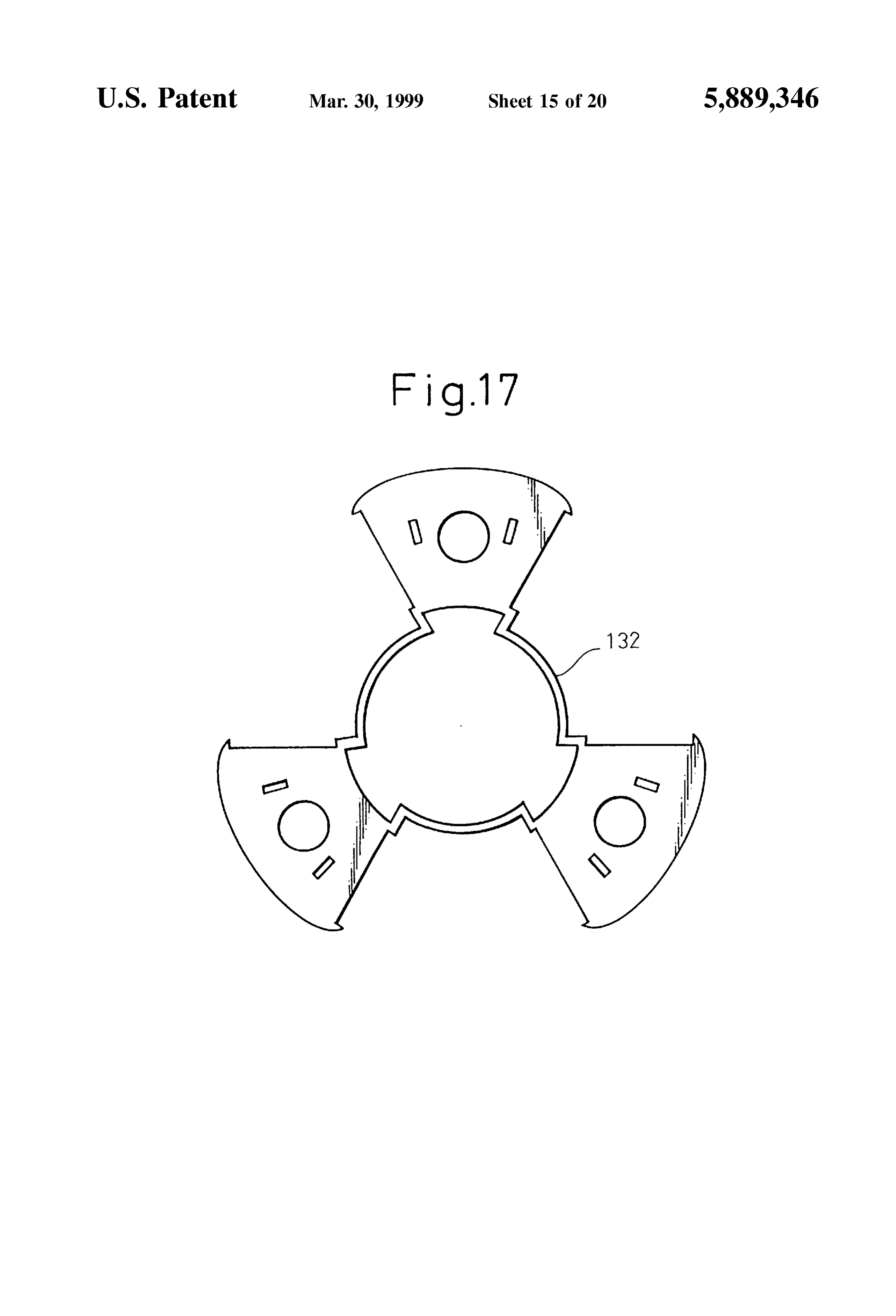
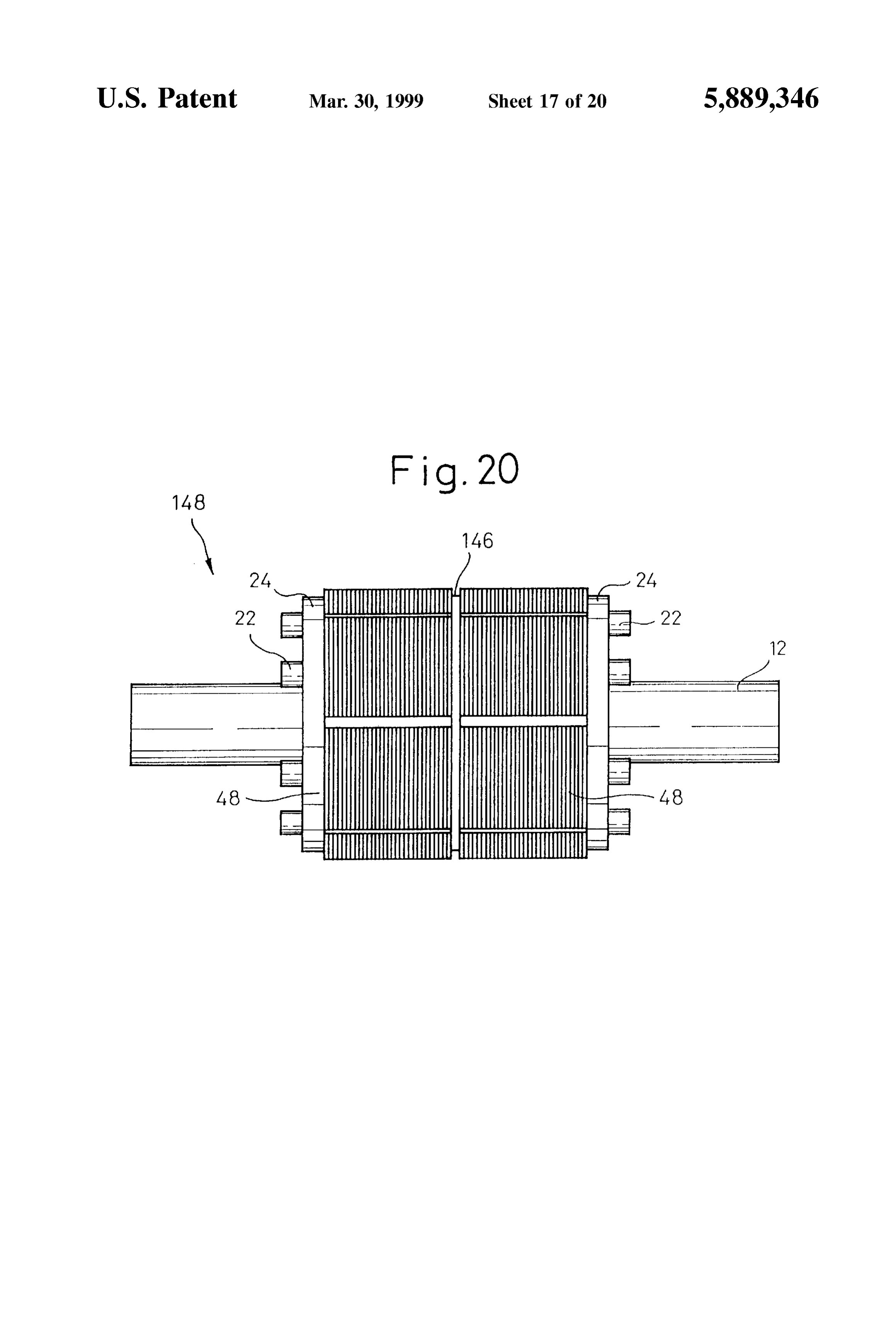
Spaced a distance of generally one-third of a laminated Embodiment 9 length from one axial end face of the laminated core member In the rotor of the embodiments 1 to 8, it is possible to 114 establishing a S-pole, and the core-lamination Sections form a high-power multi-Section rotor by disposing axially 120 thereof are joined together with the large number of Side by Side a plurality of integral laminated rotor cores with core-laminations 54 by a press-fitting process. In this the same structure. For example, as shown in FIG. 20, two manner, an integral laminated rotor core 128 for N-poles and integral laminated rotor cores 48 in the embodiment 1 are an integral laminated rotor core 130 for S-poles are formed. disposed axially side by Side through a circular plate mem Then, the integral laminated rotor core 128 for N-poles and ber 146, and are fixedly installed to the shaft 12 through the the integral laminated rotor core 130 for S-poles are rod members 22 and the end plates 24, whereby a high assembled together in Such a manner that the respective power rotor 148 can be formed. In this case, the permanent three laminated core members 112 and 114 are positioned magnets 14 of the embodiment 1 may be used as they are, alternately in a circumferential direction, and that the annu or longer permanent magnets having overall lengths corre lar connecting portions 126 of the respective integral core sponding to the total length of two integral laminated rotor laminations 116 and 118 do not interfere with each other. cores 48 may be used.
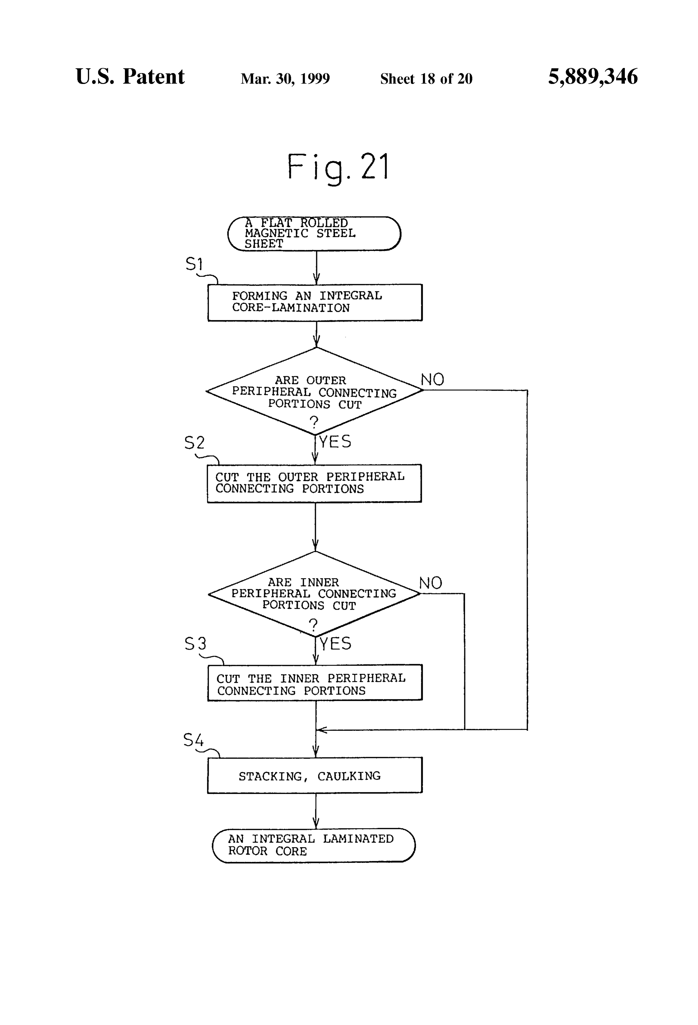
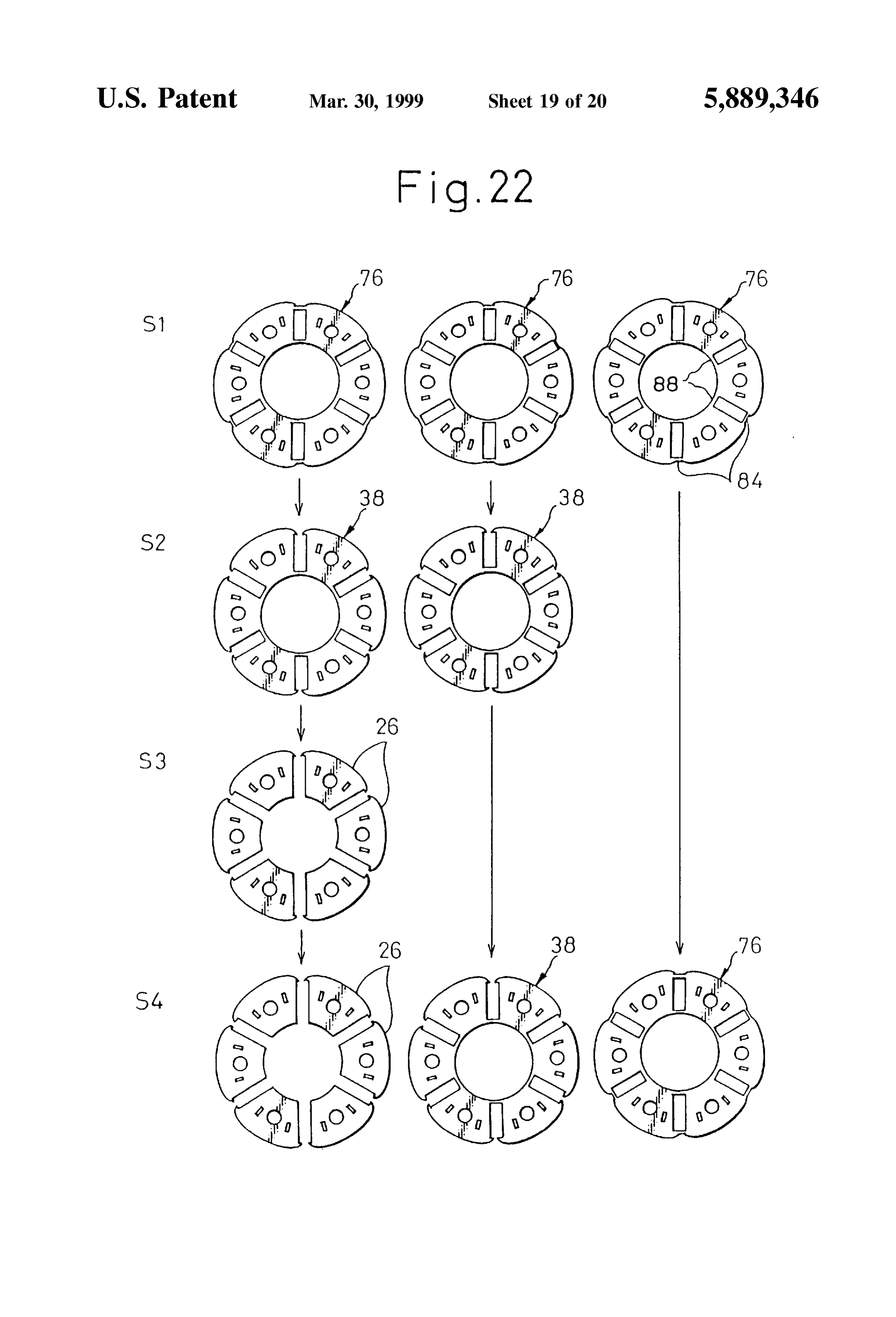
After that, the permanent magnets 14 are inserted between 15 Manufacturing Process the respective adjacent laminated core members 112, 114. In The integral laminated rotor cores of the rotors according this state, the integral laminated rotor cores 128 and 130 are to the embodiments 1 to 9 can be conveniently manufactured fixedly installed onto the shaft 12 through the rod members by one progressive die machine which can carry out various 22 and the end plates 24 in the same manner as the processes while choosing desired press-Stations, from the embodiments 1 to 6, whereby the rotor 110 shown in FIG. Viewpoint of maintaining productivity. A manufacturing 14 is formed. process for an integral laminated rotor core 96 according to In the rotor 110, the laminated core members 112, 114 of the embodiment 4 is schematically described, by way of the same magnetic poles are respectively integrated, example, with reference to FIGS. 21 and 22. In this case, an therefore, in comparison with the Structures of the embodi integral core-lamination 76 of inner and outer peripheries ments 1 to 6, in which all laminated core members are 25 connecting type (FIG. 9) is formed as a basic shape by integrated, the assembling productivity is inferior to Some Stamping a flat rolled magnetic Steel sheet, at a first Station extent but the magnetic leakage is Substantially eliminated. S1. The integral core-lamination 76 is conveyed Succes Of course, it has a Superior workability in comparison with Sively to following Stations by a conveying device of the the conventional Structure in which all laminated core mem progressive die machine. At a neXt Station S2, whether to cut bers are separated. The integral core-laminations 116, 118 outer peripheral connecting portions 84 or not is decided. If may have various arrangements and different numbers of the the integral core-lamination was not cut at the outer portions laminated core members 112, 114, other than those men 84, it is conveyed to the last station S4 so as to be used as tioned above. However, it is necessary to eliminate a mutual the integral core-lamination 76. Further at a next station S3, contact between the annular connecting portions 126 of the whether to cut inner peripheral connecting portions 88 or not integral core-laminations 116, 118 when the integral lami 35 is decided. If the integral core-lamination was not cut at the nated rotor core 128 for N-poles is assembled with the inner portions 88, it is conveyed to the last station S4 so as integral laminated rotor core 130 for S-poles. Further, a well to be used as an integral core-lamination 38 of inner periph balanced arrangement as a whole is required. ery connecting type (FIG. 4), and if the integral core The connecting construction between the core-lamination lamination was cut at the inner portions 88, it is conveyed to sections 120 of the integral core lamination 116, 118 is not 40 the last Station S4 So as to be used as Six core-laminations 26 restricted as the first and annular connecting portions 124 while keeping the relative arrangement. At the last Station and 126 as mentioned above, but may use connecting S4, the integral core-laminations 76, the integral core portions 132 each having a shape easily made by a Stamping laminations 38 and the core-laminations 26 are collected process, as shown in FIG. 17. In the case of using this shape, into the above-mentioned Stacking arrangement, and are the connecting portions 132 must be formed So as to 45 joined with each other by preSS-fitting, So as to form the eliminate any contact with the adjacent core-laminations 54 integral laminated rotor core 96.
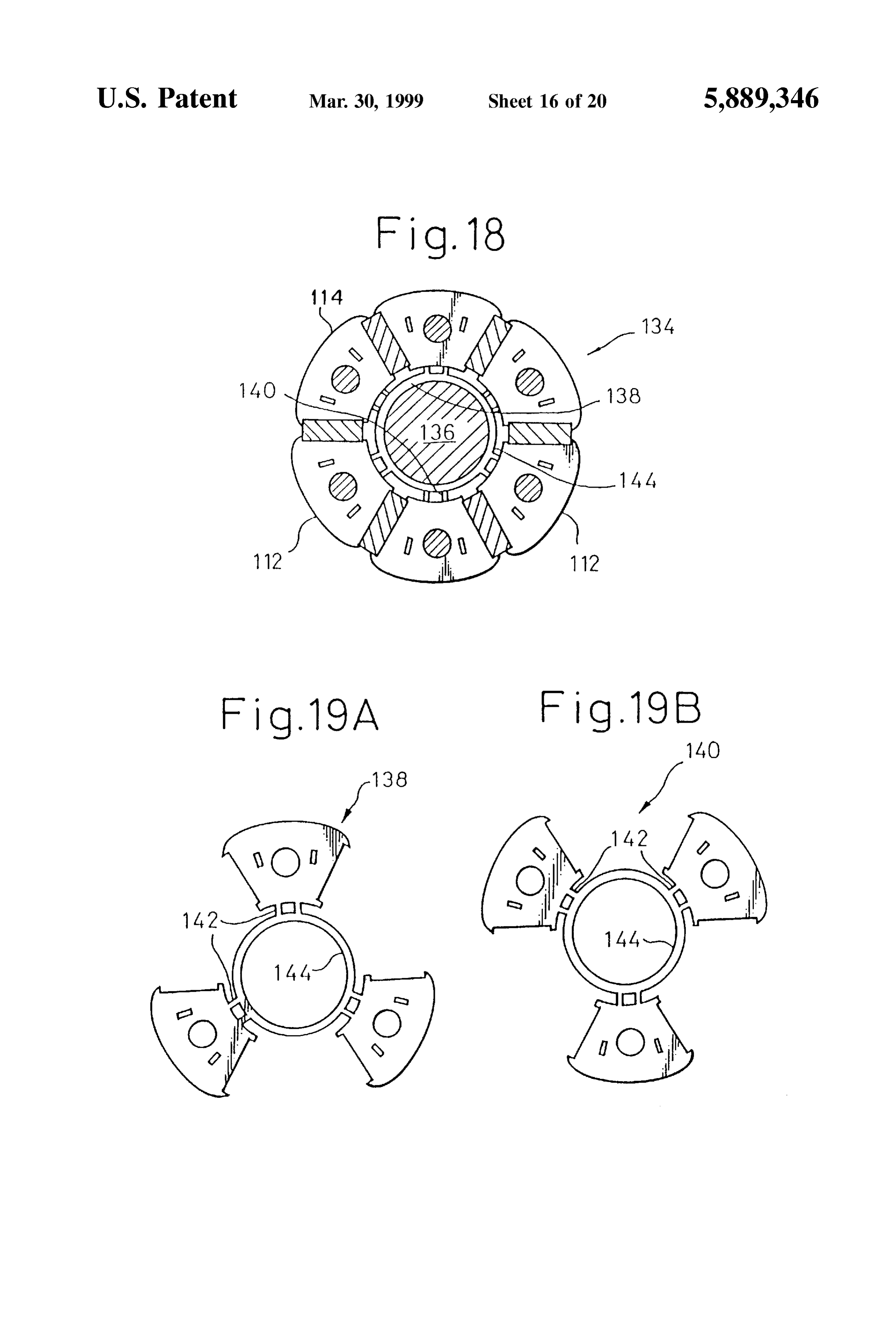
of another pole. FIG. 23 shows a manufacturing process for an integral Embodiment 8 laminated rotor core 128 for N-poles and an integral lami A rotor 134 shown in FIG. 18 includes a shaft 136 made nated rotor core 130 for S-poles according to the embodi of a non-magnetic material Such as a StainleSS Steel. Further, 50 ment 7, which uses the above progressive die machine. First, a first integral core-lamination 138 shown in FIG. 19A is an integral core-lamination (identical to the integral core used to connect the laminated core members 112 for N-poles lamination 100 in the embodiment 6), of which all core with each other, and a Second integral core-lamination 140 lamination Sections 120 are connected by an annular con shown in FIG. 19B is used to connect the laminated core necting portion 126, is formed as a basic shape by Stamping members 114 for S-poles with each other. Each of the 55 a flat rolled magnetic Steel sheet, at a first Station S1. At a integral core-laminations 138,140 has a structure similar to next station S2, whether to cut every other one of first that of each integral core-lamination 116,118 in the embodi connecting portions 124 of the core-lamination Sections 120 ment 7, but, regarding the connecting construction between or not is decided. If the integral core-lamination was not cut, the core-lamination Sections, includes a plurality of first it is conveyed to a next station S3. Further at the next station connecting portions 142 and an annular connecting portion 60 S3, whether to cut first connecting portions 124 of the 144 both having higher strength. The inner diameter of the remaining three core-lamination Sections 120 or not is annular connecting portion 144 is generally equal to the decided. If the integral core-lamination was cut at the outer diameter of the shaft 136. Therefore, the annular stations S2 and S3, it is conveyed to the last station S4, after connecting portion 144 is closely fit to the shaft 136, removing the annular connecting portion 126, So as to be whereby the mechanical strength of the rotor 134, particu 65 used as Six Separated core-laminations 54 while keeping the larly the Strength against radial load applied to the Shaft 136, relative arrangement. If the integral core-lamination was cut can be further improved. at the station S2 and was not cut at the station S3, it is

Page 27
conveyed to the last Station S4 So as to be used as a first extended between Said number of core-lamination Sec integral core-lamination 116 and three Separated core tions So as to annularly connect Said core-lamination laminations 54 while keeping the relative arrangement. If Sections, whereby Said laminated core members of the the integral core-lamination was not cut at the Station S2 and Same polarity are fixedly connected with each other in was cut at the station S3, it is conveyed to the last station S4 a relative arrangement of a finished rotor assembly. So as to be used as a Second integral core-lamination 118 and 2. A rotor as Set forth in claim 1, wherein each said at least three separated core-laminations 54 while keeping the rela one integral core-lamination includes Said core-lamination tive arrangement. At the last Station S4, the first integral Sections having shapes being generally the same as those of core-laminations 116, the Second integral core-laminations Said core-laminations of Said laminated core members and a 118 and the core-laminations 54 are collected into the number thereof being half a number of magnetic poles So as above-mentioned Stacking arrangement, and are joined with to be joined to adjacent ones of Said core-laminations, each other by press-fitting, So as to respectively form the whereby all of Said laminated core members forming mag integral laminated rotor core 128 for N-poles and the inte netic poles of the same polarity are connected in Such a gral laminated rotor core 130 for S-poles in a relative relative arrangement of a finished assembly that a Space for arrangement of a finished assembly. 15 locating one laminated core member forming another mag AS is clear from the above description, the present inven netic pole and two permanent magnets is defined between tion provides an integral laminated rotor core in which adjacent integral core-lamination Sections. laminated core members forming magnetic poles are con 3. A rotor as Set forth in claim 2, comprising an integral nected with each other, by inserting at least one integral laminated rotor core for N-poles formed by connecting all of core-lamination into the laminated Structure of the laminated Said laminated core members forming N-poles with each core members. Therefore, the work of positioning or fixing other, and an integral laminated rotor core for S-poles permanent magnets and laminated core members in an formed by connecting all of Said laminated core members assembling process of a rotor is facilitated, and productivity forming S-poles with each other Separately from Said lami is significantly improved. Further, the mechanical Strength nated core members for N-poles.
of a rotor is improved by the integral laminated rotor core. 25 4. A rotor as Set forth in claim 2, wherein Said connected Consequently, the performance and reliability of high Speed portions of Said integral core-lamination include first con or high torque motors can be improved by using the rotor necting portions extended in a radially inward direction according to the present invention. generally from centers of inner edges, opposed to Said Shaft, The present invention has been described in relation to the of respective ones of Said core-lamination Sections, and a Second annular connecting portion connecting Said first various embodiments shown in the attached drawings, but is connecting portions with each other and Surrounding Said not restricted by the above descriptions, and various changes shaft.
and modifications can be carried out without departing from the spirit and scope of the invention recited in the appended 5. A rotor as Set forth in claim 4, wherein Said shaft is claims. made of a non-magnetic material, and Said Second annular We claim: 35 connecting portion of Said integral core-lamination is 1. A rotor for a Synchronous motor comprising: engaged with an outer Surface of Said Shaft. a shaft; 6. A rotor as Set forth in claim 1, wherein Said at least one a plurality of permanent magnets disposed around Said integral core-lamination integral comprises a plurality of groups of core-laminations, Said groups being Substantially shaft at generally equal intervals, 40 equally spaced between Said end plates So as to divide Said a plurality of laminated core members each formed by laminated length of the core laminations into Several Sub axially Stacking and joining a plurality of core Stantially equal parts.
laminations made of magnetic materials, Said laminated 7. A rotor as Set forth in claim 6, wherein each group of core members being disposed around Said Shaft while integral core-laminations consists of at least two holding each of Said permanent magnets therebetween 45 laminations, and two Such groups divide Said laminated in a circumferential direction, So as to form magnetic length of the core laminations into three parts. poles; 8. A rotor for a Synchronous motor comprising: Supporting means for fixedly Supporting Said permanent a shaft;
magnets and Said laminated core members onto Said a plurality of permanent magnets disposed around Said shaft, Said Supporting means including a pair of end 50 shaft at generally equal intervals, plates disposed at both axial ends of Said laminated core members and fixed to Said Shaft and a plurality of a plurality of laminated core members each formed by rod members penetrating through Said laminated core axially Stacking and joining a plurality of core members and joined at both ends to Said end plates, laminations made of magnetic materials, Said laminated at least one integral core-lamination for each magnetic 55 core members being disposed around Said Shaft while pole polarity made of a magnetic material being the holding each of Said permanent magnets therebetween Same as that of each of Said core-laminations, each Said in a circumferential direction, So as to form magnetic integral core-lamination including a number of core poles;
lamination Sections equal to the number of laminated Supporting means for fixedly Supporting Said permanent core members of its polarity locally inserted and fixed 60 magnets and Said laminated core members onto Said between Said core-laminations forming each of Said shaft, Said Supporting means including a pair of end laminated core members of that polarity located at plates disposed at both axial ends of Said laminated positions around Said shaft, and located at a position core members and fixed to Said shaft and a plurality of between Said end plates axially dividing the laminated rod members penetrating through said laminated core length of the core-laminations into generally equal 65 members and joined at both ends to Said end plates, parts allowing magnetic and mechanical balance to be at least one integral core-lamination for each magnetic maintained, and also including connecting portions pole polarity made of a magnetic material being the
Page 28
Same as that of each of Said core-laminations, each Said Sections, whereby Said laminated core members of the integral core-lamination including a number of core Same polarity are fixedly connected with each other in lamination Sections equal to the number of laminated a relative arrangement of a finished rotor assembly; and core members of its polarity locally inserted and fixed wherein each Said at least one integral core-lamination is between Said core-laminations forming each of Said formed with a central opening of diameter greater than laminated core members of that polarity located at positions around Said shaft, and located at a position that of Said shaft, Such that a gap is defined between between Said end plates axially dividing the laminated Said at least one integral core-lamination and Said Shaft length of the core-laminations into generally equal So Said at least one core-lamination and Said core parts allowing magnetic and mechanical balance to be members are Supported against external force only by maintained, and also including connecting portions Said end plates and Said rod members. extended between Said number of core-lamination Sec tions So as to annularly connect Said core-lamination
Provenance
- Collection
- Cited prior art
- Original PDF
- patentimages.storage.googleapis.com →
- Filed
- 1998-03-20
- Pages
- 28
- Method
- pdftotext (the PDF's own text layer) + pdftoppm 300dpi page scans
- Source
- Google Patents bibliographic record
- Granted
- 1999-03-30
- Inventors
- Hiroyuki Uchida; Takashi Okamoto; Hidetoshi Uematsu; Fanuc Corp
- Transcribed from
- patentimages.storage.googleapis.com →