patent · US4087698
Alternating current power generating system
2 May 1978
Page 1 — bibliographic record
United States Patent (19) 11) 4,087,698 Myers (45) May 2, 1978 (54) ALTERNATING CURRENT POWER FOREIGN PATENT DOCUMENTS
GENERATING SYSTEM
952,340 5/1949 France ................................. 310/122 75 Inventor: John E. Myers, Littleton, Colo. 280,888 10/1927 United Kingdom ................. 310/122 Primary Examiner-L. T. Hix 73 Assignee: Franklin W. Baumgartner, Denver, Assistant Examiner-Stafford D. Schreyer Colo. Attorney, Agent, or Firm-Sheridan, Ross, Fields & McIntosh 21) Appl. No.: 789,853 57 ABSTRACT 22 Filed: Apr. 22, 1977 A system for generating alternating current of selected voltage at a target frequency includes a plurality of (51) Int. Cl”...................... H02K 19/34; H02K 19/36 A.C. generators, at least one of which has a rotatably (52) U.S. C. ...................................... 307/84; 310/122; mounted stator. A prime mover drives a power input 322/32 shaft at speeds extending through a wide range and the (58) Field of Search ............... 307/84, 72,73; 310/10, shaft is connected to the first rotor. As speed increases, 310/13, 112, 113, 114, 116, 118, 122; 322/32, the generator reaches the desired frequency and a sens 63; 290/4A, 4 R ing device releases the stator to rotate and maintain a relative speed between itself and the rotor correspond ing to the target frequency. The stator drives the second (56) References Cited rotor at its own absolute speed which is the difference
1,971,818 8/1934 Hoxie ..................................... 307/53 speed between the first stator and rotor. A field control 2,039,322 5/1936 Lell ......... 318/172 maintains the desired voltage and a load control trans 2,061,983 11/1936 Rossman . ... 318/47 mits the current output to a load and varies the load to 2,782,329 2/1957 Kirby ...... ... 307/72 maintain the generator at proper operating condition. 3,070,740 12/1962 Chirgwin ... 322/32 3,421,061 1/1969 Baughman ........................... 318/172 23 Claims, 4 Drawing Figures
N ala
FED LOAD FIELD LOAD
CONTROL CONTROL CONTROL CONTROL w
REFERENCE
LOAD
PHASE
OCK 90 LOCK
Page 2
Drawing sheet — no readable text.
Page 3
Drawing sheet — no readable text.
Page 4
The control apparatus may be mounted in a console,
ALTERNATING CURRENTPOWER GENERATING and includes a field control assembly, a load control SYSTEM assembly, and a phase lock assembly appropriately in BACKGROUND OF THE INVENTION terconnected. The load control assembly is selectively connectable to a first or second type of load and con
The system and method of this invention lie in the trols the load to maintain proper operation of the gener field of alternating current generation with controlled ator. Each stator shaft is mounted in a bearing which voltage and frequency to enable connection to a power incorporates lock means to prevent rotation of the sta supply system carrying current at predetermined volt tor under control of the phase lock assembly. The field age and frequency. They are directed particularly to the 10 control assembly provides the necessary excitation for utilization of a prime mover which drives a power input the rotor field. Separate consoles may be provided for shaft at widely varying speeds with a range extending each generator.
well above that necessary to produce current at selected In operation, assuming the prime mover to be origi voltage and target frequency, which shaft drives one or nally at a standstill, it commences to rotate and drives more generators without modifying control of the shaft 15 the power input shaft at increasing speed. The shaft speed. correspondingly drives the first rotor which cooperates Various schemes have been proposed and utilized for with the stationary stator to produce alternating current driving and controlling the speed of motors and genera at increasing frequency. The phase lock assembly com tors and have been generally satisfactory for the pur pares the output frequency with that supplied by a pose. In the field of electrical current generation the 20 source of reference voltage and frequency, and when output frequency of the generator has been maintained the target frequency is attained, the phase lock assembly at a desired value, and hence the angular velocity of the releases the bearing lock to allow the first stator to rotor, by comparing the generated frequency with a rotate and maintain a relative speed between itself and standard reference frequency and modifying the rota the first rotor corresponding to the target frequency. tional speed of a driving turbine to cause them to match. 25 The absolute speed of the first stator is the difference Other systems have maintained the proper angular ve between the speed of the power input shaft and the locity of the rotor by interposing a mechanical variable relative rotational speed between itself and the first speed transmission in the drive line between a prime rotor. The first stator drives the second rotor at this mover and the rotor shaft. It has also been proposed to absolute speed.
control the speed of an induction motor by rotating its 30 At any time when the first generator is producing frame, or stator, at different speeds, an auxiliary motor current below the target frequency, the load control being used to produce the rotation of the frame. Among transmits such current to a load which does not require examples of these various types of devices might be target frequency. When the target frequency is attained mentioned the U.S. Pat. Nos. 1971,818 to Hoxie, the current may continue to be transmitted to this first 2,039,322 to Lell, and 2,061,983 to Rossman. 35 type of load or it may selectively be transferred to a While systems such as those mentioned are well power supply system carrying current at the target suited to installations in which stored energy is used for frequency. The second generator operates in the same the power supply and hence the power may be reduced way, and if the power input shaft speed increases be without waste of energy, they are not practical for use yond the point where the second stator is released, it when the source of energy cannot be stored and varies may drive a third rotor or a dynamic brake. over a wide range, such as relative wind driving wind BRIEF DESCRIPTION OF THE DRAWINGS mills or air turbines. If the full energy is not used it is lost and cannot be recovered at a later time. Various other advantages and features of novelty will SUMMARY OF THE INVENTION become apparent as the description proceeds in con 45 junction with the accompanying drawings, in which:
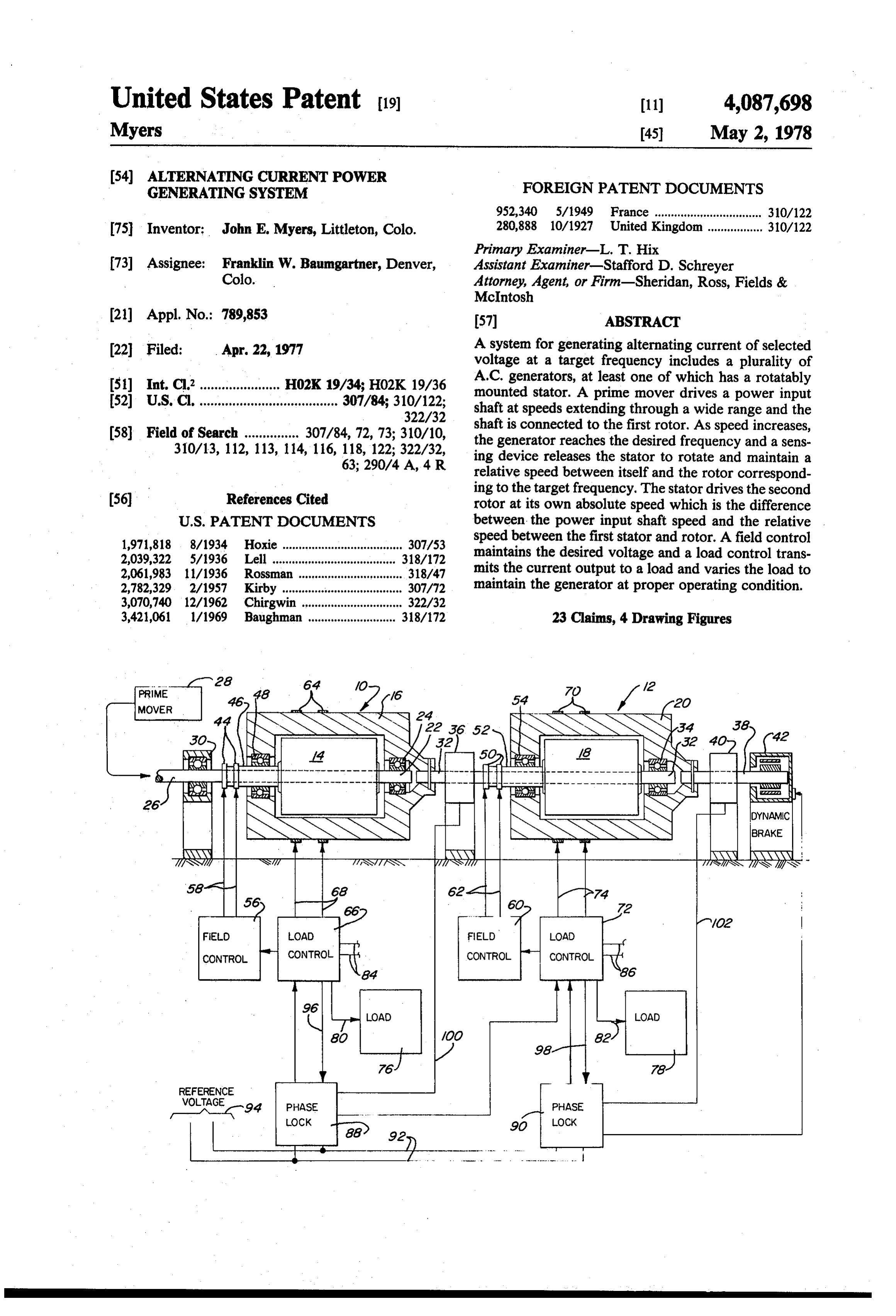
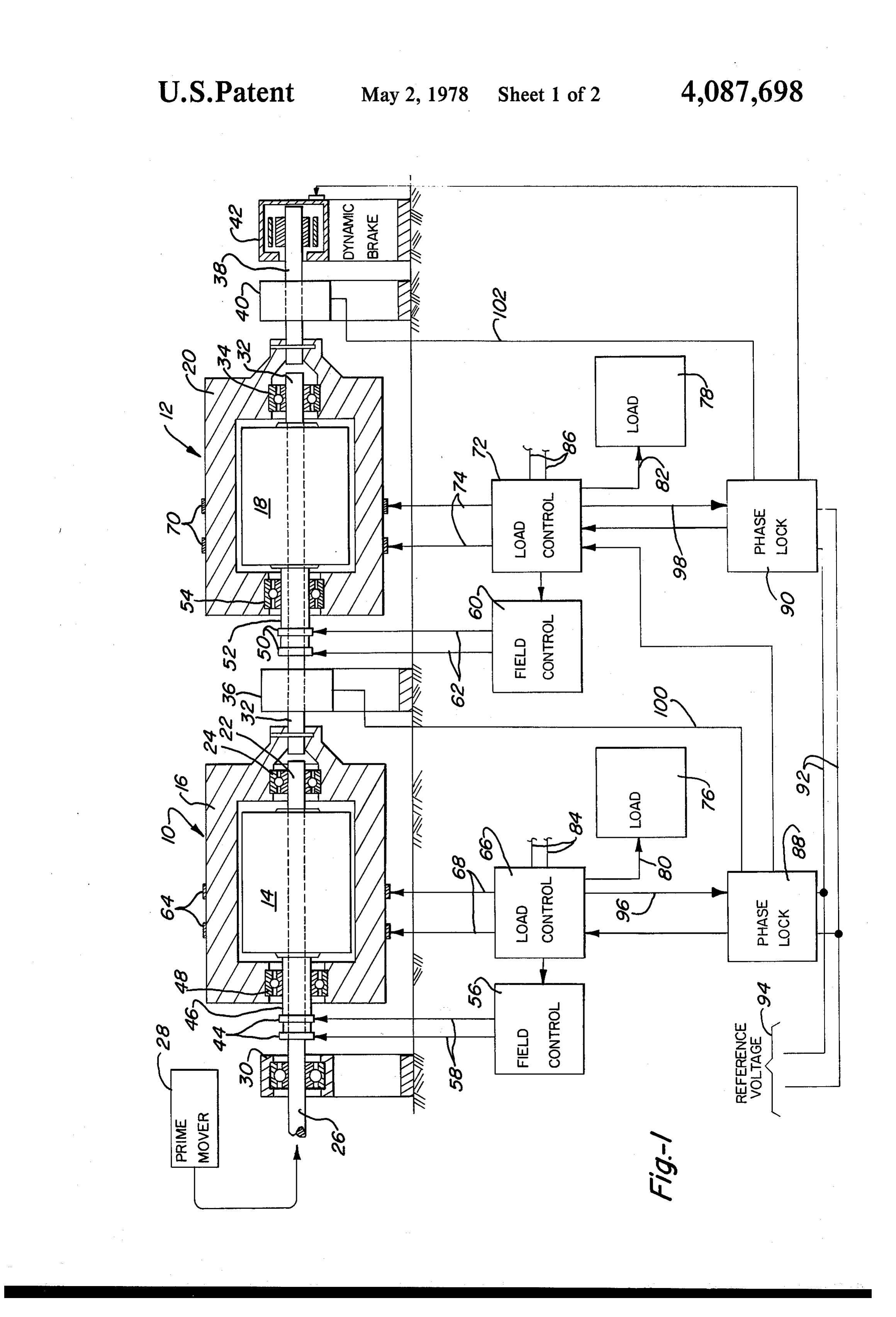
The apparatus incorporating the features of the pres FIG. 1 is a schematic view of the system showing two ent invention overcomes the disadvantages mentioned generators and a dynamic brake;
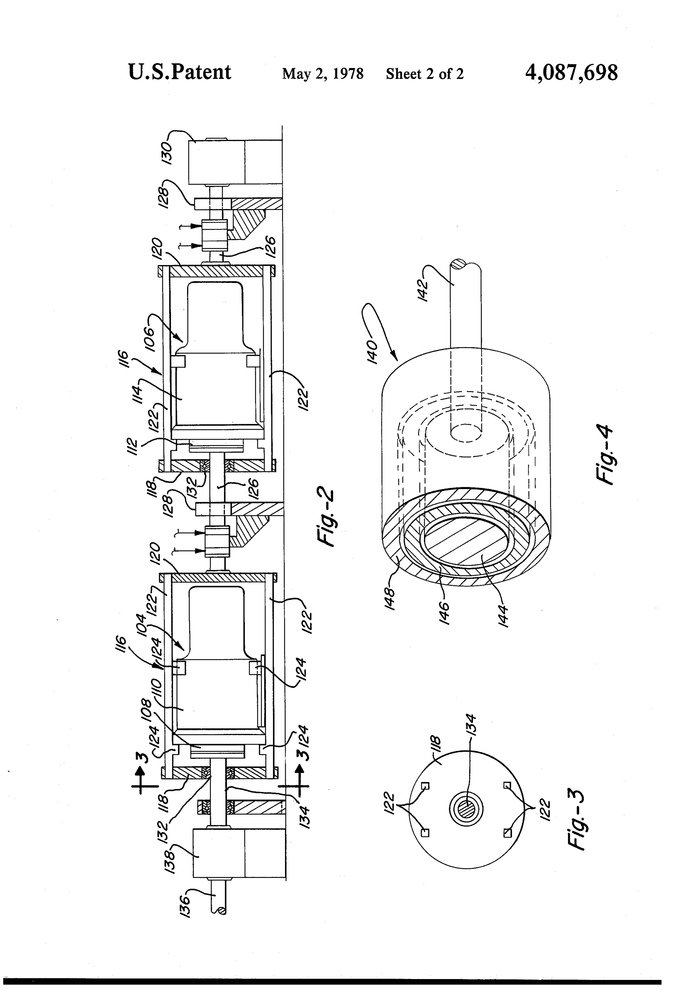
above and provides a relatively simple system for utiliz FIG. 2 is a view similar to FIG. 1 showing a modified ing all of the energy available from an uncontrolled form of generator and rotatable supporting frame; prime mover which may operate at widely varying 50 FIG. 3 is a view taken on line 3-3 of FIG. 2; and speeds. FIG. 4 is an idealized representation of a two genera Generally stated, the system in preferred form in tor assembly in a concentric configuration. cludes at least two alternating current generators with the stator of the first generator connected in driving DESCRIPTION OF PREFERRED relation to the rotor of the first generator and a power 55 - EMBODIMENTS
input shaft connected in driving relation to the first The general arrangement of a system incorporating rotor, the shaft being adapted to be driven by a prime the features of the invention is schematically illustrated mover which may be a windmill or wind turbine capa in FIG. 1, in which two substantially identical genera ble of rotating the shaft at speeds in a range extending tors 10 and 12 are shown arranged in tandem. Generator well above that required for production of current from 10 has a rotor 14 and stator 16 and generator 12 has a a single generator at selected voltage and a target fre rotor 18 and stator 20. Rotor 14 is mounted on shaft 22 quency. The first stator is rotatably mounted but is which is carried by bearing 24 in one end of stator 16. initially releasably locked against rotation. In the event The outer end of shaft 22 becomes the power input shaft that the power and speed of the drive shaft are great 26 connected to prime mover 28 and carried by bearing enough the second stator may be rotatably mounted and 65 30.
initially locked in the same way. The second stator may Rotor 18 is mounted on shaft 32 which is carried by be drivingly connected to a third generator rotor or to bearing 34 in one end of stator 20. The outer end of shaft a dynamic brake. 32 extends into and is locked to the outer end of stator

Page 5
16 and is carried by bearing 36. Another shaft 38 ex stator 20 is released to rotate, it drives shaft 38 and the tends into and is locked to the outer end of stator 20 and remaining power is absorbed by dynamic brake 42. In also extends through bearing 40 and into dynamic brake the event that it is known in advance during the engi 42. Field slip rings 44 for rotor 14 are mounted in sleeve neering and design stages that the relative wind power 46 which is carried by bearing 48 in the end of stator 16. 5 at the station location will be frequently well in excess Similar slip rings 50 for rotor 18 are mounted on sleeve of the capacity of two generators, then one or more 52 which is carried by bearing 54 in the end of stator 20, additional generators may be added to the series, with Field control 56 is connected by conductors 58 to slip the stator of the last generator drivingly connected to rings 44 and field control 60 is connected by conductors the dynamic brake.
62 to slip rings 50. Stator 16 is provided with slip rings 10 The apparatus of FIG. 1 is intended primarily for 64 to carry current from the generator, and load control producing current suitable for incorporation into a stan 66 is connected by conductors 68 to slip rings 64. Stator dard system such as public service network and the 20 is provided with slip rings 70 to carry current from stators would be initially designed for the rotatable the generator, and load control 72 is connected by con mounting as shown. If it is desired to provide a rela ductors 74 to slip rings 70. Non-critical loads within 76 15 tively small, low power system utilizing standard con and 78 are selectively connectable by load controls 66 ventional generators, it may be somewhat modified as and 72 respectively as indicated at 80 and 82. Conduc indicated in FIG. 2.
tors 84 and 86 lead from load controls 66 and 72 to a In this form, two conventional single bearing AC standard power transmission system operating at se generators 104 and 106 are provided, such generators lected voltage and the target frequency and are selec 20 being constructed tively connectable through the load controls to the 104 has a rotor 108for stationary mounting. Generator outputs of the generators. Phase lock assemblies 88 and has a rotor 112 and a astator and stator 110, and generator 106 114. Each generator is 90 are connected through conductors 92 to a source of mounted in a frame 116 consisting reference voltage and frequency 94 and through con a second disk 120 tied together byoffour a first disk 118 and beams 122 hav ductors 96 and 98 and the load controls to the outputs of 25 ing projections 124 to fixedly engage and the generators. In addition, each phase lock assembly is stator. Similarly to FIG. 1 each second disksupport the is provided connected by conductors 100 and 102 to the locking with a shaft 126 supported in a lockable bearing 128. means, not shown, in bearings 36 and 40 respectively.
In considering the operation of the system, the prime The first shaft 126 drives rotor 112 and the second shaft mover 28 is considered to be initially at a standstill and 30 126 extends into dynamic brake 130. Disks 118 are car is assumed to be a windmill or wind turbine. When the ried on bearings 132, one of which is mounted in rotor relative wind velocity is sufficient to produce adequate shaft 126 and the other on rotor shaft 134. Power input power the prime mover commences to rotate, driving shaft 136 drives a step-up, step-down transmission 138 the power input shaft 26 at increasing speeds. The shaft which drives shaft 134 in an appropriate speed range. correspondingly drives rotor 14 which cooperates with 35 FIG. 4 illustrates a concept of a dual generator sys stationary stator 16 to produce alternating current at tem in which a second generator is arranged in concen increasing frequency. The rotational speed of rotor 14 tric overlying relation to a first generator. In this figure, may for varying periods of time remain so low that the the system 140 includes a power input shaft 142 con frequency of the current produced is less than the target nected to a first rotor 144. Member 146 is a rotatably frequency. During such periods the current passes 40 mounted ring or cylinder carrying an inner winding to through conductors 68 to load control 66 and is distrib serve as a first stator and an outer winding to serve as a uted to load 76 which is non-critical and can utilize second rotor. Member 148 represents the rotatably power at non-standard frequencies. mounted second stator. A construction of this general Phase lock 88 continuously monitors the output fre nature will be equipped to operate in the same manner quency of the generator through conductors 96 and 45 as the construction of FIG. 1, and stator 148 would be compares it with that supplied by the reference voltage provided with means to drive an additional rotor or and frequency source 94. When the target frequency is dynamic brake.
attained, phase lock 88 releases the lockinbearing 36 by What is claimed is:
way of conductor 100 and allows stator 16 to rotate and 1. An alternating current power generating system maintain a relative speed between itself and rotor 1450 comprising:
corresponding to the target frequency. The absolute a plurality of alternating current generators, each speed of stator 16 is the difference between the speed of having corresponding first generating components the power input shaft 26, and rotor 14, and the relative and corresponding second generating components; rotational speed between itself and rotor 14. Stator 16 all of the components being rotatably mounted, with then drives rotor 18 of the second generator at this 55 the second components being releasably restrained absolute speed. against rotation;
When the target frequency is attained the current a rotatable power input shaft adapted to be driven by may continue to be transmitted to the non-critical first a prime mover at widely varying speeds; type load 76 if needed or desired, or it may be selec the power input shaft being connected in driving tively transferred through conductors 84 to a power relation to the first component of a first generator, supply system carrying current at the target frequency, and each second component being connected in phase lock 88 serving to lock the generator into the driving relation to the first component of a succes system. sive generator, with the second component of the Once stator 16 begins rotation, shaft 32 becomes in last generator in the series being connected in driv effect a power input shaft in the same way as shaft 26, 65 ing relation to a controllable load; and the operation of generator 12 follows the same the range of rotational speed of the power input shaft pattern as that described for generator 10. When the extending well above that required to produce a output of generator 12 reaches the target frequency and selected target frequency in at least one generator;
Page 6
and sensing and control means operative to selec shaft and the relative rotational speed between the tively and sequentially sense the attainment of the rotor and stator of the first generator. target frequency of the current produced by the 9. An alternating current power generating system first and successive generators and to act in re comprising:
sponse to the attainment of such frequencies to 5 a plurality of alternating current generators, each initially release the second component of the first having rotatably mounted rotors and stators; generator and allow it to rotate and maintain a a rotatable power input shaft adapted to be driven by relative rotational speed between itself and the first a prime mover at widely varying speeds; component corresponding to the target frequency the power input shaft being connected in driving and to drive the first component of the second 10 relation to the first rotor; generator, and to sequentially release the second the first stator being connected in driving relation to components of successive generators as they attain the second rotor;
the target frequency. the second stator being connected in driving relation 2. A system as claimed in claim 1; in which to a controllable load; field control means are electrically connected to the 15 a field control assembly for each generator electri field winding of each generator to produce a se cally connected to its rotor to provide controlled lected voltage at the target frequency. excitation;
3. A system as claimed in claim 1; in which a load control assembly for each generator electri the sensing and control means include adjustable load 20 cally connected to its stator; control means connecting the output of each gener lock means associated with each stator to prevent ator to a load and operable to vary the load and rotation;
maintain the proper operating condition of the a phase lock assembly electrically connected through generator. its respective load control assembly to each respec 4. A system as claimed in claim 3; in which tive stator to sense the frequency of the current the load control means is selectively connectable to a 25 produced by the generator, and electrically con first type of load to absorb the output of the genera nected to its respective lock means; tor at less than the target frequency and selected and a source of reference voltage at a target fre voltage. quency connected to each phase lock assembly; 5. A system as claimed in claim 3; in which the range of rotational speed of the power input shaft the load control means is selectively connectable to a 30 extending well above that required to produce the second type of load to absorb the output of the target frequency in at least one generator; generator at the target frequency and selected volt the first phase lock assembly being operative to sense age. the frequency of the current produced by the first 6. A system as claimed in claim 5; in which generator and compare it with the target frequency the second type of load is a power supply system 35 and to act in response to the attainment of such carrying current at the target frequency and se frequency and release the first lock means to allow the first stator to rotate and maintain a relative lected voltage. speed between itself the first rotor corresponding 7. A system as claimed in claim 1; in which to the target frequency and to drive the second the load to which the second component of the last rotor.
generator in the series is connected is a dynamic 10. A system as claimed in claim 9; in which brake. the load control assembly is connected to a load to 8. An alternating current power generating system transmit the output of its generator to the load, and comprising: is operable to vary the load and maintain the first and second alternating current generators, each 45 proper operating condition of the generator. having a rotor and a stator; 11. A system as claimed in claim 10; in which the stator of the first generator being rotatably the load control assembly is selectively connectable mounted and connected in driving relation with to a first type of load to absorb the output of the the rotor of the second generator; generator at less than the target frequency and means to releasably lock the stator of the first genera 50 selected voltage.
tor against rotation; 12. A system as claimed in claim 10; in which a rotatable power input shaft connected in driving the load control assembly is selectively connected to relation to the rotor of the first generator and a second type of load to absorb the output of the adapted to be driven by a prime mover at widely generator at the target frequency and selected volt varying rotational speeds in a range extending well 55 age.
above that required to produce a selected target 13. A system as claimed in claim 12; in which frequency in the first generator; the second type of load is a power supply system and means operative to sense the attainment of the carrying current at the target frequency and se target frequency of the current produced by the lected voltage.
first generator in response to increasing rotational 14. A system as claimed in claim 9; in which speed of the power input shaft and to act in re the controllable load to which the second stator is sponse to the attainment of the target frequency to connected is a dynamic brake.
release the stator of the first generator and allow it 15. A system as claimed in claim 9; in which to rotate and maintain a relative rotational speed the controllable load to which the second stator is between itself and the stator corresponding to the 65 connected comprises at least one additional genera target frequency and to drive the rotor of the sec tor, with the stator of the last generator in the series ond generator at a speed corresponding to the being connected to a dynamic brake. difference between the speed of the power input 16. A system as claimed in claim 9; in which
Page 7
each stator is provided with a drive shaft; driving the rotor of each successive generator from a supporting bearing is provided for each drive shaft; the stator of the preceding generator at increasing and the lock means is connected to the bearing and rotational speeds until such generator produces selectively operable to cause it to bind the drive current at the target frequency; shaft and prevent its rotation. and repeating the stator rotation and driving steps 17. A system as claimed in claim 9; in which within the range of rotational speed of the power the source of reference voltage at target frequency is input shaft.
a power supply system carrying current at selected 21. The method as claimed in claim 20; further includ
18. A system as claimed in claim 9; in which O selectively transmitting the output of each generator a rotatably mounted frame is provided for each sta to a first type of load to absorb the output at less tor; than the target frequency and a selected voltage and each stator is fixedly mounted in its frame for and to a second type of load to absorb the output at rotation with respect to its rotor. the target frequency and selected voltage. 19. A system as claimed in claim 9; in which 15 22. The method as claimed in claim 20; further includ the components of the generators are arranged in 1ng concentric overlying relation; transmitting the output of each generator to a load the innermost component being the first rotor; and varying the load to maintain the proper operat the second component surrounding the first rotor ing condition of the generator. comprising the first stator and the second rotor; 20 23. The method of generating and supplying alternat and the third component surrounding the second ing current at a selected target frequency from a genera component being the second stator. tor driven from a power input shaft having a range of 20. The method of generating and supplying alternat rotational speed extending well above that required to ing current at a selected target frequency from a plural produce the selected target frequency in the generator, ity of generators driven from a power input shaft hav 25 the method comprising:
ing a range of rotational speed extending well above driving the rotor of the generator from the power that required to produce the selected target frequency input shaft at increasing rotational speed until it in at least one generator, the method comprising: produces current at the target frequency; driving the rotor of a first generator from the power causing the stator of the generator to rotate and main input shaft at increasing rotational speed until the 30 tain a relative rotational speed between itself and generator produces current at the target frequency; the rotor corresponding to the target frequency, causing the stator of the first generator to rotate and with its absolute rotational speed being the differ maintain a relative rotational speed between itself ence between the rotational speed of the shaft and and the rotor corresponding to the target fre the relative rotational speed between the stator and quency, with its absolute rotational speed being the 35 the rotor;
difference between the rotational speed of the shaft and causing the stator to drive the rotor of a second and the relative rotational speed between the stator generator.
and the rotor; k . . . .
Provenance
- Collection
- Cited prior art
- Original PDF
- patentimages.storage.googleapis.com →
- Filed
- 1977-04-22
- Pages
- 7
- Method
- pdftotext (the PDF's own text layer) + pdftoppm 300dpi page scans
- Source
- Google Patents bibliographic record
- Granted
- 1978-05-02
- Inventors
- John E. Myers
- Transcribed from
- patentimages.storage.googleapis.com →