patent · US6232673
Windmill
15 May 2001
Page 1 — bibliographic record
(12) United States Patent (10) Patent No.: US 6,232,673 B1 Schoo et al. (45) Date of Patent: May 15, 2001
(54) WINDMILL 4,871,923 * 10/1989 Scholz et al. .......................... 290/55
FOREIGN PATENT DOCUMENTS
(75) Inventors: Alfred Schoo; Arno Klein-Hitpass, both of Bocholt (DE) 0037002A1 * 10/1981 (EP).
(73) Assignee: A. Friedr. Flender AG, Bocholt (DE) 0635639A1 * 1/1995 (EP).
(*) Notice: Subject to any disclaimer, the term of this 9521326 * 8/1995 (WO).
patent is extended or adjusted under 35 96.11338 * 4/1996 (WO).
U.S.C. 154(b) by 0 days. * cited by examiner (21) Appl. No.: 09/547,012 Primary Examiner Thomas M. Dougherty Assistant Examiner Joseph Waks (22) Filed: Apr. 11, 2000 (74) Attorney, Agent, or Firm Max Fogiel (30) Foreign Application Priority Data (57) ABSTRACT Apr. 12, 1999 (DE) .............................................. 19916 453 A wind-power plant with a rotor. The rotor's hub is accom (51) Int. Cl." .................................................... F03D 9/00 modated in a roller bearing. The roller bearing is mounted on (52) U.S. Cl. ............................ 290/55; 290/1 C; 475/342; a Support and connected to a planetary gear. The planetary 60/398 gear comprises two stages, Specifically an input Stage and an (58) Field of Search ................................ 290/55, 44, 1 C, output Stage. The planetary gear's output shaft is coupled by 290/4 C; 475/162,342; 60/398 way of a clutch to a generator. The roller bearing (3) has an inner ring (7) that is attached to and can be detached from (56) References Cited both the hub (1) and the rotating part of the planetary gear. The generator (11) has a housing that is combined with and
2,653,250 11/1953 Romani ................................ 290/4 C drive-train module. The module rests on the rotor support (4) 3,792,629 2/1974 Applebury ... ... 475/342 and can be dynamically Separated from the overall plant. 4,239,977 * 12/1980 Strutman ................................ 290/44 4,440,044 4/1984 Heller ................................... 475/162 7 Claims, 5 Drawing Sheets
Page 2
Drawing sheet — no readable text.
Page 3
Drawing sheet — no readable text.
Page 4
Drawing sheet — no readable text.
Page 5
Drawing sheet — no readable text.

Page 6
Drawing sheet — no readable text.
Page 7
WINDMILL Roller bearing 3 has a Stationary outer ring 6 and a rotating inner ring 7. Outer ring 6 is rigidly fastened to rotor
The present invention concerns a wind-power plant as support 4. Hub 1 is screwed onto inner ring 7 and is provided recited in the preamble to claim 1. with Several bores that accommodate take-along bolts, pref Ecology and the economy exert ever more Stringent erably rubberized to suppress vibration.
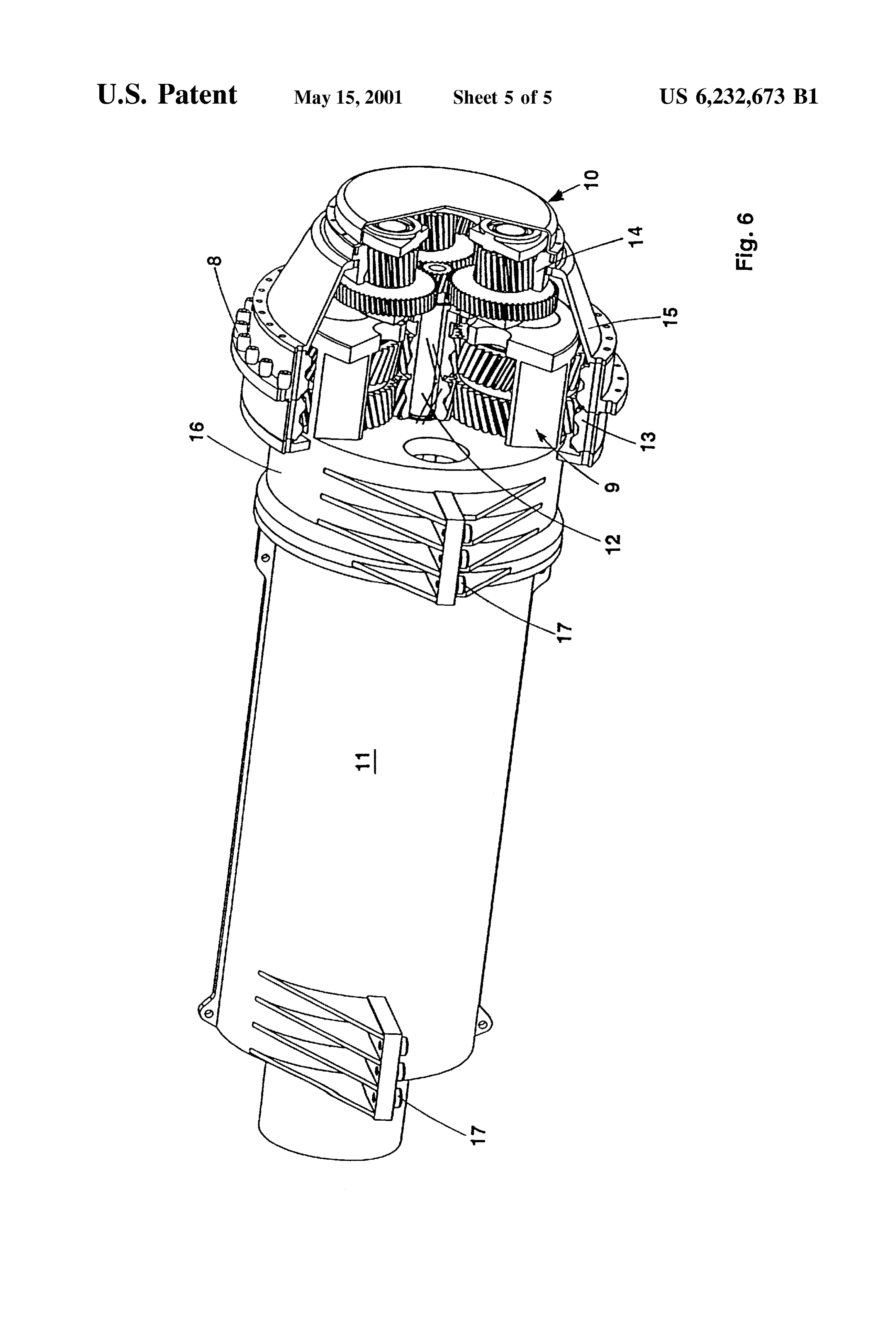
demands on contemporary wind-power plants. The economy The wind-power plant also includes a transmission in the requires that Such plants be not only light in weight but also form of a two-stage planetary gear comprising an input stage 9 and an output stage 10. Planetary gears of this form are inexpensive to install, repair, and maintain. Off-shore in generally particular, the installation of a wind-power plant entails only to theknown extent and the present example will be specified that it is relevant to understanding of the considerable expenditure, for on-board cranes and helicop invention. Each Stage of the planetary gear includes a Sun ters for example. Ecology on the other hand requires the wheel, Several planetary wheels accommodated in a plan minimalization of noise from off-shore. These objectives etary Support, and a hollow wheel, all of which mutually entail total Separation of the individual components.
The transmission trains employed in known wind-power planetary housing in output Stage stage mesh. The Sun wheel 12 in input
9 is connected to the
The axle of Sun wheel plants (European Published Patent 635639) comprise rotor 15 12 constitutes the gear's output shaft and is coupled to the blades, a hub with a shaft and bearing Set, a multiple-stage shaft of a generator 11.
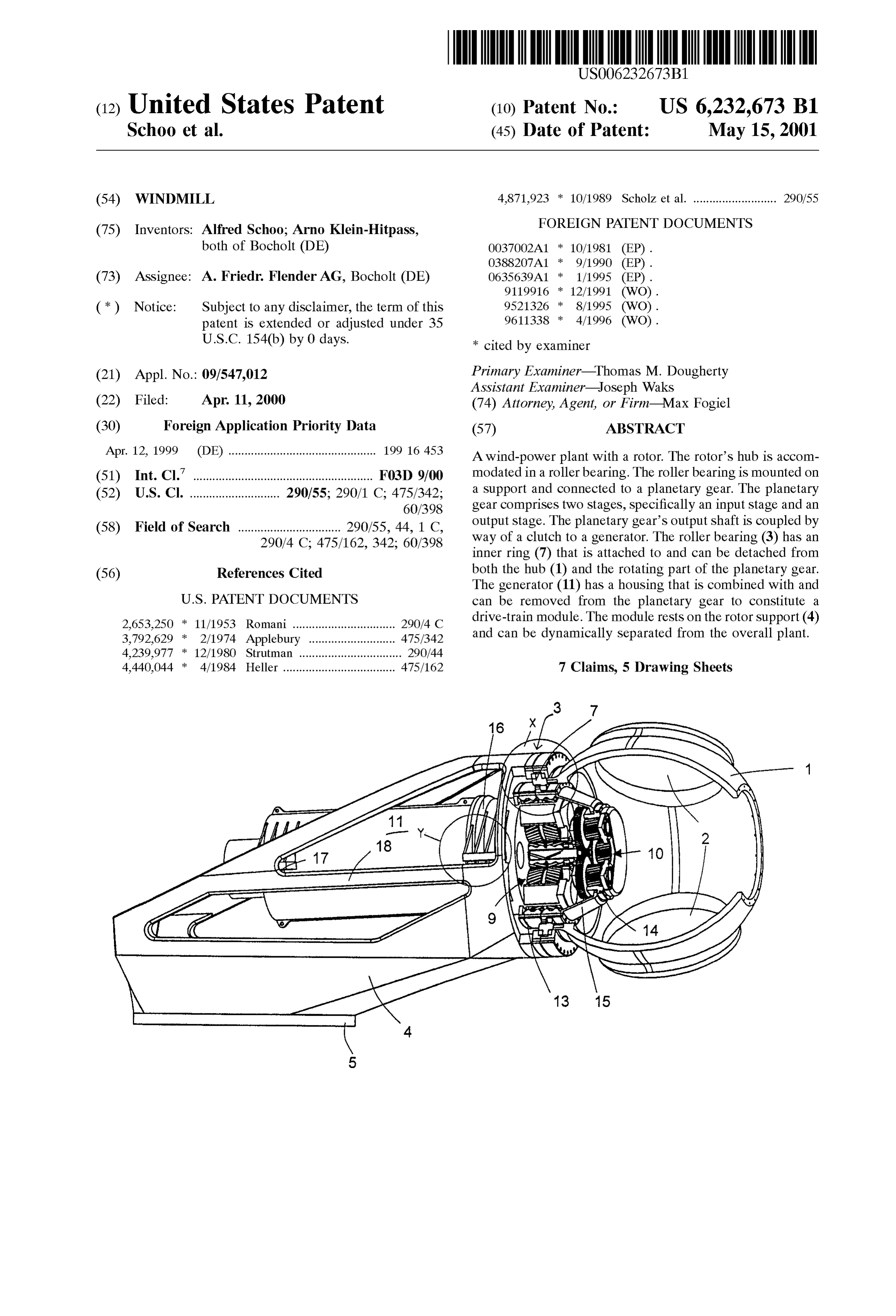
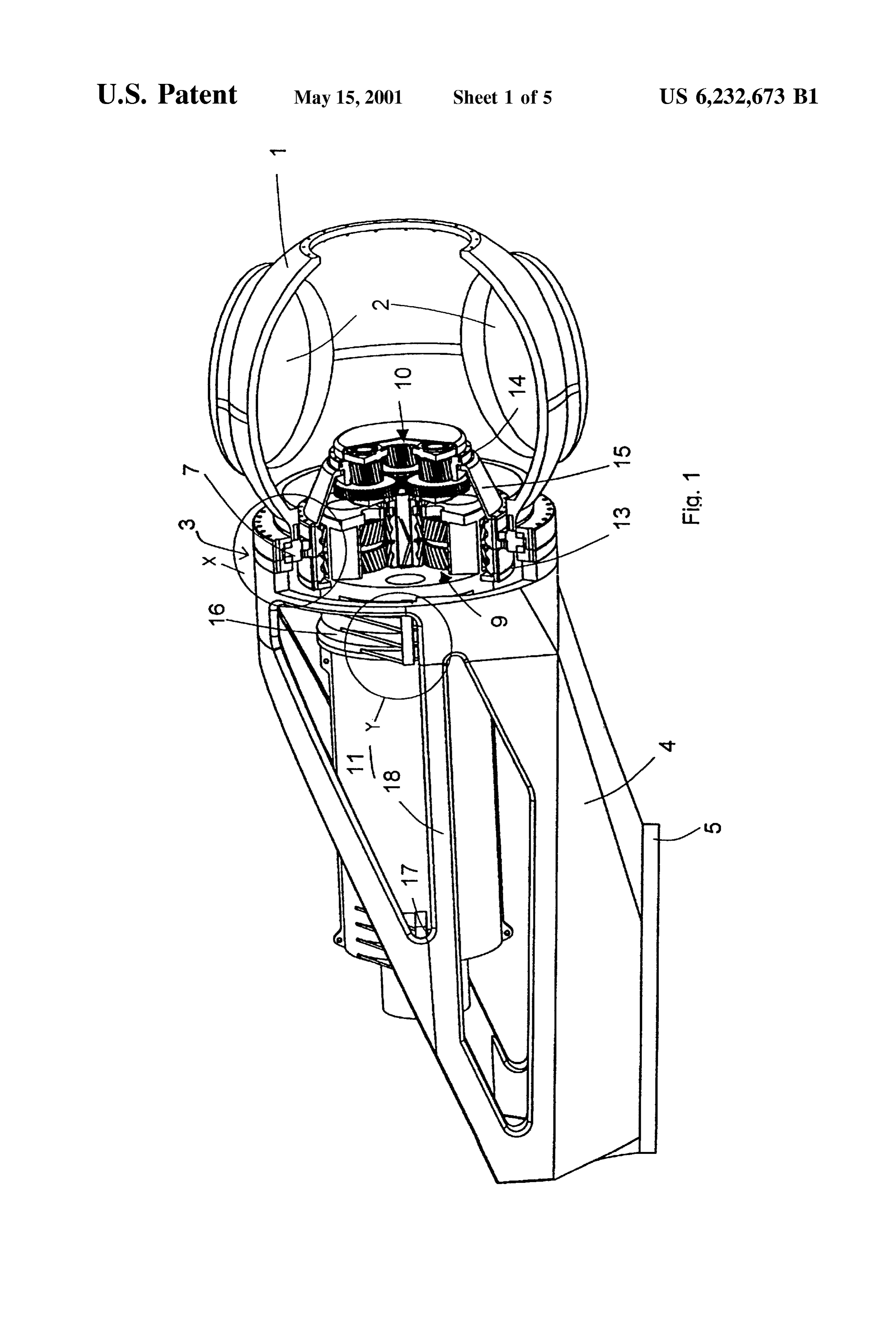
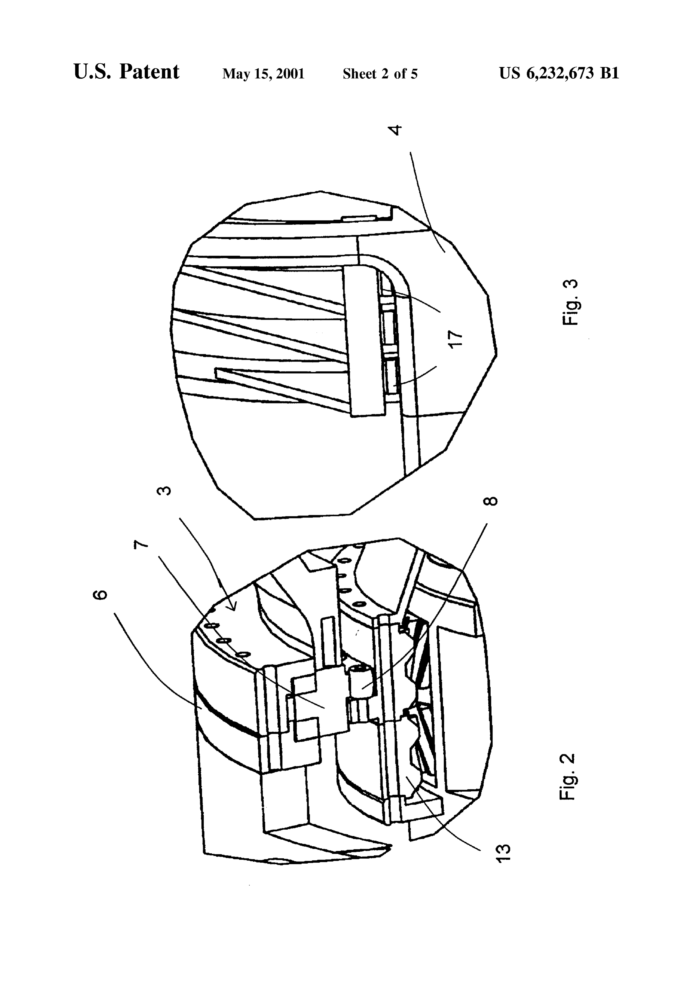
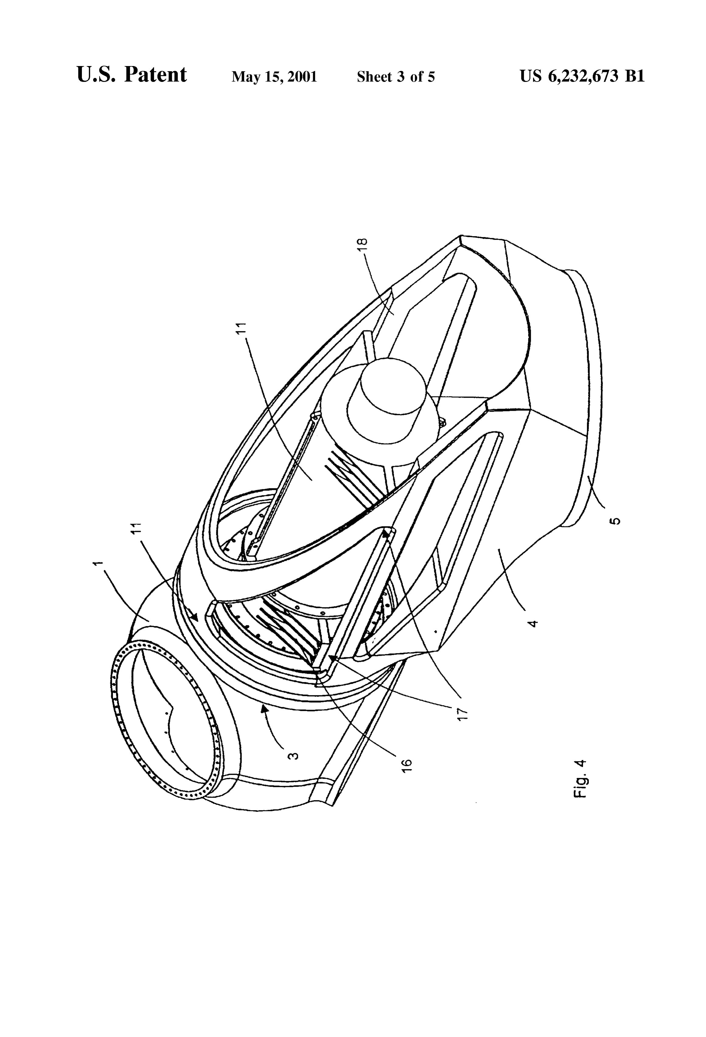
planetary gear, a mechanical brake, a coupling, and a gen The inner ring 7 in roller bearing 3 is connected to the erator. The blades are mounted on the hub and rotate the hollow wheel 13 in input stage 9 by way of take-along bolts shaft. The shaft is accommodated in a large roller bearing 8. The power provided to the rotor is accordingly forwarded connected to an azimuth bearing by way of a frame. The to the planetary gear. The hollow wheel 13 in input stage 9 force of the wind against the rotor are accordingly trans is connected to another hollow wheel 14 in the output stage mitted to a mast. This bearing System requires interposing 10 in the planetary gear's rotating housing 15. Due to the part of the shaft between the rotor and the transmission. The connection between the hollow wheel 13 in housing 15 and downstream roller bearing consists of a transmission Section the inner ring 7 in roller bearing 3, both housing 15 and hub with a hollow input shaft that is connected to the rotor shaft 25 1 are accommodated in the wind-power plant's roller bear by an overturned disk. The Overall transmission is also ing 3. Planetary Support 16 forwards the reaction torque mounted on the frame by way of a two-armed torque deriving from the planetary gear into rotor Support 4. accommodating Strut. The transmission's high-Speed drive Since generator 11 is Screwed onto the Stationary plan shaft is connected to the generator's high-Speed Shaft by way etary Support 16 in input Stage 9, the planetary gear and of a double linkage coupling. The latter Shaft is also mounted generator 11 are combined into a Single drive-train module. on a frame in the machinery housing. A brake is installed This module is connected to rotor Support 4 by way of between the generator and the transmission. This known vibration suppressors 17. The connection between hub 1 and Wind-power plant occupies a lot of Space and is accordingly the planetary gearby way of the rubberized take-along bolts restricted in capacity. Furthermore, is complicated to mount 8 in the inner ring 7 in roller bearing 3 and the attachment and dismount. 35 of the planetary gear and generator 11 by way of vibration The object of the present invention is a wind-power plant SuppreSSorS 17 results in total dynamic isolation of the that will be more compact and easier to install, repair, and drive-train module from the rest of the wind power plant. maintain. This reduces the plant's overall weight in that the module Combining the transmission and generator into a single can be quite Small.
drive-train module, along with the Special connection 40 How the wind-power plant is installed will now be between the module and rotor hub and the roller bearing, Specified. First, the rotor-Support unit, comprising rotor allows the components to be simply and rapidly mounted on Support 4, mounting rails 18, roller bearing 3, and hub 1, is the already installed rotor Support. Furthermore, the drive mounted on the mast. Next, the rotor blades are lifted train module is not coupled to the rotor Support. The forces, through their accommodations and positioned therein by a torques, and deformations exerted by the wind on the rotor 45 crane mounted on rotor Support 4. The same crane can be hub, the roller bearing, and the rotor Support will have no employed to raise the drive-train module, comprising the negative effects on the transmission or generator. planetary gear and generator 11, onto rotor Support 4. The One embodiment of the present invention will now be module can also be removed from hub 1 along mounting Specified with reference to the accompanying drawing, rails 18 and lowered by the crane for repair and mainte wherein 50 nance. The wind-power plant's modular construction also FIG. 1 is a partly longitudinal-Sectional and partly per allows the planetary gear and its Subassemblies and genera Spective view of a wind-power plant, tor 11 to be removed from the mast by the crane individually FIG. 2 is a larger-scale detail of the area X in FIG. 1, or as a whole and replaced. It is in off-shore applications in FIG. 3 is a larger-scale detail of the area Yin FIG. 1, particular that Such a modular approach can considerably FIG. 4 depicts the structure of the plant's mast head, 55 reduce the expense of maintaining a wind-power plant. FIG. 5 illustrates the plants rotor Support, and Furthermore, downtime can be extensively decreased in the FIG. 6 is an overall view of the wind-power plant. event of damage.
The hub 1 of a rotor employed in a wind-power plant is What is claimed is:
provided with accommodations 2 for blades. Hub 1 is itself 1. Wind-power plant with a rotor having a hub being accommodated in a known type of large-scale roller bearing 60 accommodated in a roller bearing, the roller bearing being 3, which constitutes a radially Secured axial bearing. Bearing mounted on a rotor Support and connected to a planetary 3 is attached to a rotor Support 4. Rotor Support 4 is gear, the planetary gear comprising two stages, Specifically connected to an unillustrated mast by way of an azimuth an input stage and an output Stage, and a planetary gear bearing 5. The forces exerted by the wind on the rotor's output Shaft being coupled by way of a clutch to a generator, blades are accordingly diverted directly into the mast. AZi 65 wherein:
muth bearing 5 is engaged by an azimuth drive mechanism the roller bearing has an inner ring that is attached to and that maintains the wind-power plant facing into the wind. can be detached from the hub
Page 8
the generator has a housing that is combined with and can output Stage are connected to a rotating transmission hous be removed from the planetary gear to constitute a ing accommodated in the roller bearing.
drive-train module, and 5. Wind-power plant as of claim 1 wherein a planetary the module rests on the rotor Support and can be separated Support in the input Stage rests on the rotor Support.
6. Wind-power plant as in claim 5, wherein the planetary 2. Wind-power plant as in claim 1, having the inner ring Support in the input Stage forwards a reaction torque from of the roller bearing attached to a hollow wheel in the the planetary gear into Said rotor Support. planetary gear input Stage by bolts.
3. Wind-power plant as in claim 2, wherein the bolts 7. Wind-power plant as of claim 1 wherein the drive-train SuppreSS Vibrations. 10 module rests on vibration Suppressors on the rotor Support. 4. Wind-power plant as in claim 2, wherein the hollow wheel in the input Stage and another hollow wheel in the
Provenance
- Collection
- Cited prior art
- Original PDF
- patentimages.storage.googleapis.com →
- Filed
- 2000-04-11
- Pages
- 8
- Method
- pdftotext (the PDF's own text layer) + pdftoppm 300dpi page scans
- Source
- Google Patents bibliographic record
- Granted
- 2001-05-15
- Inventors
- Alfred Schoo; Arno Klein-Hitpass; A Friedrich Flender AG
- Transcribed from
- patentimages.storage.googleapis.com →