patent · US5783894
Method and apparatus for generating electrical energy
21 July 1998
Page 1 — bibliographic record
United States Patent 19 11 Patent Number: 5,783,894 Wither 45) Date of Patent: Jul. 21, 1998 54 METHOD AND APPARATUS FOR 5,262,693 l 171993 Holka ...................................... 310/12 GENERATING ELECTRICAL ENERGY 5,272,378 12/1993 Wither ..................................... 290/1 R 5.311,092 5/1994 Fisher ...................................... 310/266 76 Inventor: Thomas A. Wither, 1204 Grove Ave., 5,341,060 8/1994 Kawamura .............................. 310/153 Royal Oak, Mich. 48067 5,350,991 9/1994 Bae ............. ... 318/727 5,495,131 2/1996 Goldie et al. ............................. 30/2
Primary Examiner Thomas M. Dougherty 22 Filed: Oct 31, 1995 Assistant Examiner-K. Tamai (51) Int. Cl. ........... H02K 16/04 Attorney, Agent, or Firm-Harness Dickey & Pierce P.L.C. 52) U.S. Cl. ......................... 310/266; 310/156; 310/264: 57 ABSTRACT
(58) Field of Search ..................................... 310/266, 156, An apparatus for generating electrical energy includes at 310/261, 264, 268 least one fixedly mounted stator having a generally cylin drical cross-section and further including an inner periphery 56 References Cited and an outer periphery. The apparatus additionally includes a rotor which is mounted for rotation relative to the stator
1.591,435 7/1926 Rohde ..................................... 310/266 stator to extendabout its periphery preferably in a serpentine 2,722,617 11/1955 Cluwen et al. ......................... 3.0/103 manner. Further, the apparatus includes first and second 3.247,407 4/1966 Bruneel. groups of permanent magnets. The first group of permanent 4,318,019 3/1982 Teasley et al. .......................... 30,156 magnets is mounted to the rotor and is axially arranged about 4,371,801 2/1983 Richter .................................... 310/156 the axis such that the first group of magnets faces the inner 4,618,792 10/1986 Yates ....................................... 310,156 periphery of the stator. The second group of magnets is 4,692,631 9/1987 Dahl ......................................... 290/55 mounted to the rotor and is arranged about the axis such that 4,692.646 971987 Gotou ..... . 310184 4,703,211 10/1987 Yazaki et al. 310/79 the second group of permanent magnets faces the outer 4,763,050 8/1988 Ruppert ................................... 3.18/254 periphery of the stator.
4,866,321 9/1989 Blanhard et al. .. ... 310/112 5,184,040 2/1993 Lim ......................................... 30/14 1 Claim, 2 Drawing Sheets
Page 2
Drawing sheet — no readable text.
Page 3
Drawing sheet — no readable text.
Page 4
METHOD AND APPARATUS FOR electrons will move along the conducting member. The GENERATING ELECTRICAL ENERGY electrons will move until the forces due to the motion of the conducting member through the magnetic field are balanced
BACKGROUND OF THE INVENTION by electrostatic forces that arise because electrons collect at 1. Technical Field one end of the conducting member, thereby leaving a deficit The present invention relates generally to a method and of electrons at the other end. Thus, an electric field along the apparatus for generating electrical energy from a mechanical conducting member, and hence a potential difference input. More particularly, the present invention relates to a between the ends of the conducting member exists while the generator which utilizes the force of magnetic attraction or motion continues.
repulsion between permanent magnets to generate extremely Various electric machines presently in use are premised high induced electrical output values and a method of using on the above general relationship. For example, a generator the generator. customarily utilizes one member to provide a magnetic field 2. Discussion and another member, the stator, to form a conductor which An important consideration in the preservation and 15 can tors carry a current under the influence of the field. Genera constructed upon these principles have heretofore been improvement of the environment is the control and elimi nation of pollution associated with the by-products of proposed for use with turbines powered by wind currents. numerous techniques utilized in the production of bulk However, such arrangements have also been associated electric power. The production of bulk electric power for with significant disadvantages. For example, the efficiencies industrial, residential, and rural use generally employs large of known generators have rendered such arrangements cost Scale production of electric power in stationary plants ineffective. In this regard, the relative orientations of the designed specifically for those purposes. Typically, the gen conducting members and magnetic fields in known genera erating units in these plants convert energy from the foll tors are subject to improvement lowing sources of raw energy: water, coal, natural gas, oil In view of the above, a need clearly exists to develop both and nuclear fuels to electrical energy. While known tech 25 a method and an apparatus for generating electrical energy niques for generating electricity have proven to be commer having significantly improved efficiency. cially viable, all are fraught with one or more drawbacks. SUMMARY OF THE INVENTTON Such drawbacks include, but are not limited to, the cost of equipment utilized for conversion, the cost and availability It is a principal object of the present invention to provide of the raw sources of fuel, and the actual and potential 30 a method and apparatus for generating electrical power from contamination of soil, water and the atmosphere from pol a moving magnetic field in such a way so as to realize a lution. maximum efficiency with a relatively high electrical output It is also known that wind currents can be successfully value in relation to the motive power or input required. harnessed for conversion to electrical power. In fact, the It is a related object of the present invention to provide a rudimentary use of wind currents dates back to sailing ships 35 generator in which the voltage induced in a conductor and windmills. Modernly, a significant amount of interest member results from the mutual opposition or attraction has developed in wind currents relating to the production of between the magnetic fields of permanent magnets, while at electricity with wind turbines. Wind currents represent a the same time reducing the magnetic opposition to rotation source of raw fuel which is abundant and clean. and substantially increasing the electrical outputs of the Furthermore, wind currents have no associated costs and individual magnetic field producing elements. will not be subject to depletion. It is an additional object of the present invention to Modern wind turbine technology has demonstrated the provide an apparatus for generating power which is suitable potential for alleviating the demanding and escalating for replacing or supplementing conventional methods for energy needs of the United States as well as the rest of the generating power during times of peak demand for electrical world. Most typically, energy from wind currents is har 45 power.
nessed through an arrangement of numerous rotors individu It is a further object of the present invention to provide an ally coupled to generators. In a typical application, wind apparatus currents cause the blades of the rotors to spin and each to operate for producing electrical energy which is adapted generator outputs accurrent which travels through a cable eliminate costs and close in areas to population centers, and thereby power losses associated with the transfer into a remote field transformer. The voltage is increased and 50 of electrical energy over significant distances. sent to a substation that converts it to an even higher voltage.
The resulting power can be distributed over utility transmis generatorAnother object of the present invention is to provide a sion lines and converted to a usable voltage at remote pole capable of producing extremely high voltages transformers before it is ultimately received by the con through a novel orientation of permanent magnets and field Sle. 55 windings by creating mutual interference with or interaction It is also known to utilize a moving magnetic field for the between the magnetic fields under relative motion. purpose of generating an electric field and therefore an It is yet another object of the present invention to provide electromotive force, by electromagnetic induction. In an apparatus for generating power which utilizes raw fuel in essence, the electromotive force or voltage is induced by the the form of wind currents produced by vehicular traffic in action of magnetic lines of force cutting an electrical con areas of substantial traffic flow.
ductor due to the movement of the magnetic field relative to It is still yet another object of the present invention to the conductor. More particularly, where a conducting mem provide an apparatus for generating power which produces ber such as a bar or wire moves through a magnetic field, an increased magnetic field, allows for the incorporation of each free electron within the conducting member experi additional conductive material, and defeats magnetic oppo ences a force due to its motion through the field. If the 65 sition to rotation.
direction of the motion is such that a component of the force These and other objects of the present invention are on the electrons is parallel to the conducting member, the provided by an apparatus for generating electrical energy
Page 5
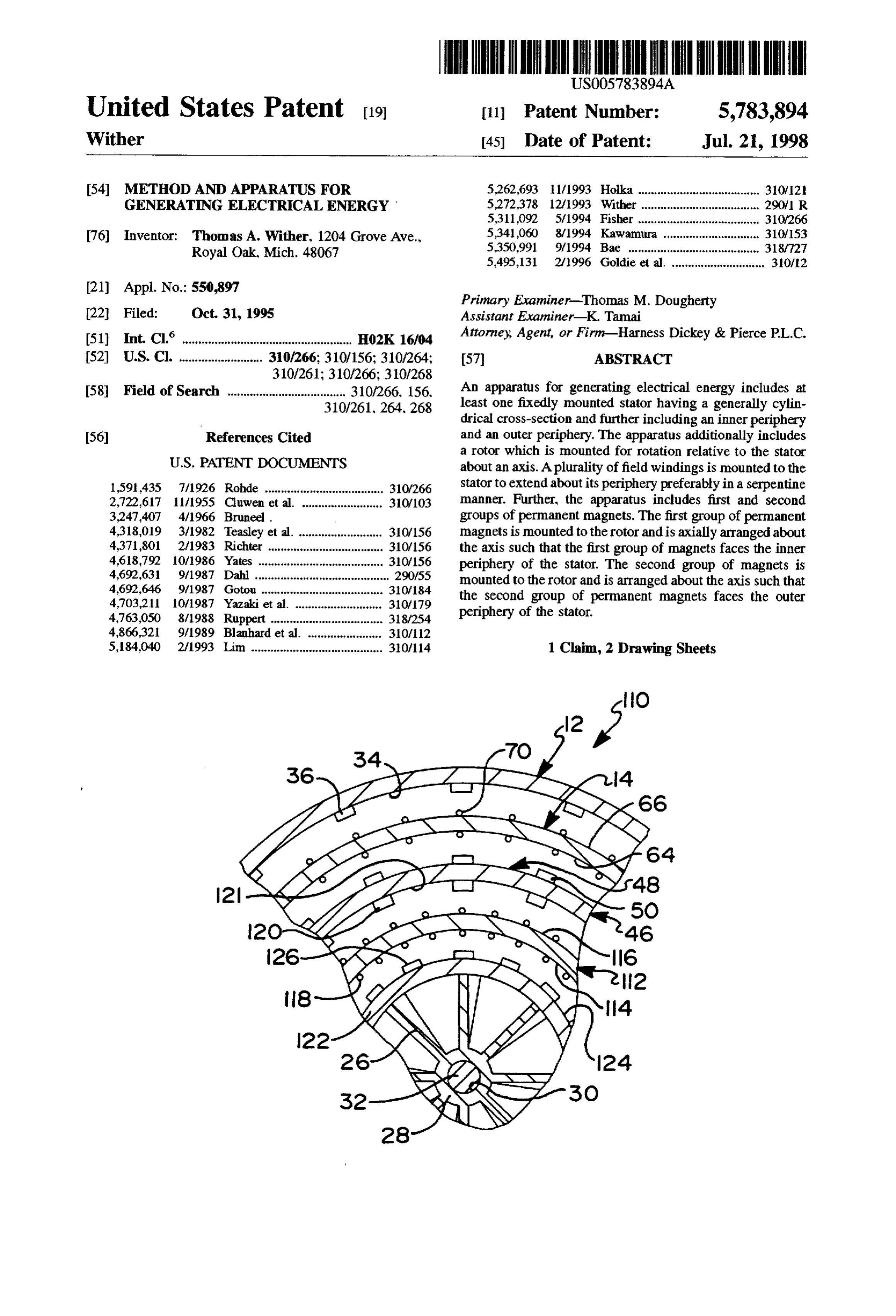
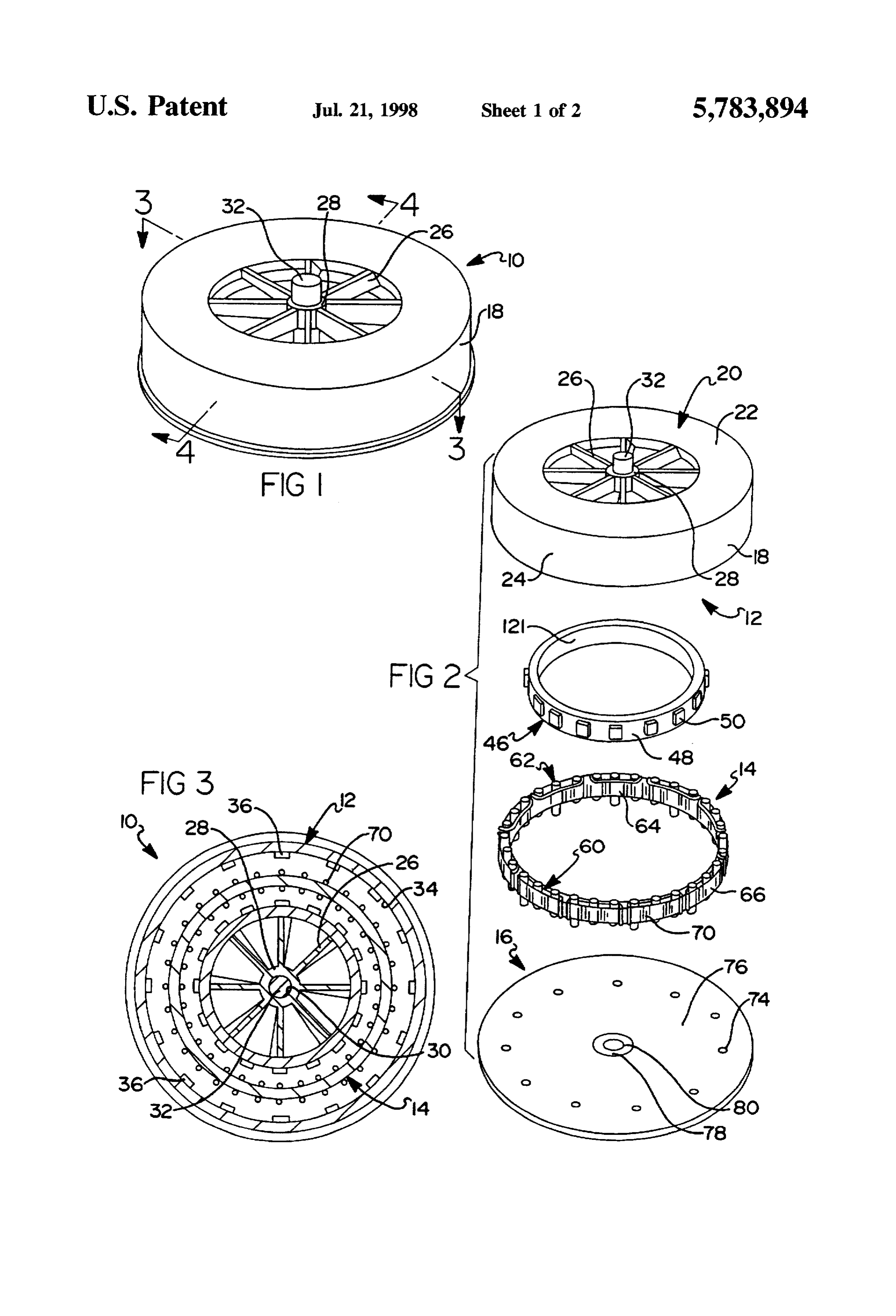
which includes a fixedly mounted stator and first and second further part hereof, and to the accompanying descriptive groups of permanent magnets mounted for rotation relative matter, in which there is illustrated and described preferred to the stator. In the preferred embodiment, the first and embodiments of the present invention. second groups of permanent magnets are arranged concen trically to one another at different radial distances about a BRIEF DESCRIPTION OF THE DRAWENGS common axis of rotation and the fixedly mounted stator is In the drawings in which reference numerals include concentrically interdisposed between the first and second corresponding components throughout the several views: groups of permanent magnets. FIG. 1 is a perspective view of a generator constructed in In one preferred embodiment, the apparatus of the present accordance with a first preferred embodiment of the present invention is directed to an apparatus for generating electric O invention;
ity which includes a rotor and a stator. The stator has a FIG. 2 is a partially exploded view of the generator of generally cylindrical cross-section and includes an inner FIG. ;
periphery and an outer periphery. The rotor is mounted for rotation relative to the stator about an axis. The apparatus FIG. 3 is a cross-sectional view along the line 3-3 of further includes a plurality of field windings mounted to the 15 FIG. 1;
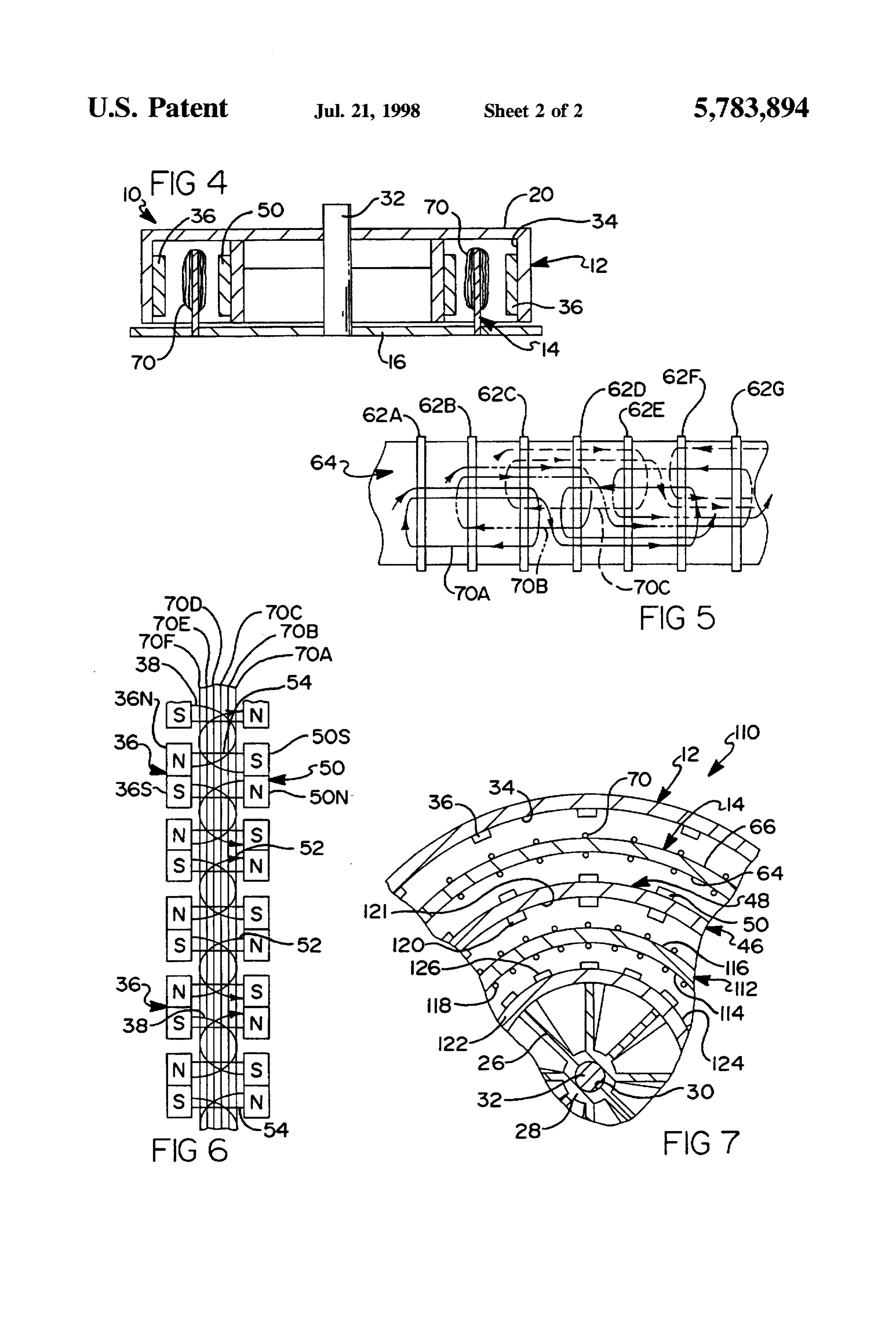
stator to extend about its periphery in a serpentine manner. FIG. 4 is a cross-sectional view along the line 4-4 of Additionally, the apparatus includes first and second groups FIG. 1;
of permanent magnets. The first group of permanent mag FIG. 5 is an enlarged diagrammatically representation nets is mounted to the rotor and is axially arranged about the illustrating the three-phase winding pattern of the field axis of rotation such that the first group of magnets faces the windings attached to the outer peripheral surface of the inner periphery of the stator. The second group of magnets stator of FIGS. 2-4;
is mounted to the rotor and is arranged about the axis such FIG. 6 is a diagrammatically representation of the lines of that the second group of permanent magnets faces the outer magnetic force established between the first and second periphery of the stator. groups of permanent magnets and the orientation of the lines In another preferred embodiment, the apparatus of the 25 of magnetic force relative to the three phase windings of the present invention is directed to an apparatus for generating stator; and electrical power which includes a fixedly mounted stator. FIG. 7 is a partial view similar to FIG. 3 illustrating the The fixedly mounted stator has a generally cylindrical inner orientation of the field windings and permanent magnets in periphery and a generally cylindrical outer periphery. The 30 a generator constructed in accordance with the teachings of apparatus further includes first and second groups of per a second preferred embodiment of the present invention. manent magnets. The permanent magnets of the first and The following detailed description utilizes various termi second group are axially arranged relative to one another nology intended to indicate general direction for purposes of about a common axis. The first and second groups are further describing the figures to which reference is being made. For arranged concentrically at different radial distances about the axis. The apparatus further includes a first plurality of 35 example, it will be understood that the terminology "clock wise" and "counterclockwise" will be used as a convenience field windings mounted to extend about the inner periphery of the stator in a serpentine manner such that the first to designated relative directions in the drawings. plurality of field winding is facing the first group of perma DETALED DESCRIPTION OF THE nent magnets. Similarly, a second plurality of field windings PREFERRED EMBODIMENTS is mounted to extend about the outer periphery of the stator The present invention is directed to an apparatus for in a serpentine manner such that the second plurality of field generating windings is facing the second group of permanent magnets. invention iselectrical directed energy. More specifically, the present to an improved generator which is
The apparatus further includes means for rotating the first highly effective for harnessing a low source of raw energy and second groups of permanent magnets relative to said 45 for conversion to electrical energy. One anticipated exem first and second plurality of field windings. plary use of the generator of the present invention is in The method of the present invention is directed to a cooperation with a wind turbine for generating electrical method of generating electrical energy which includes the energy from captured wind currents. A thorough description steps of: of a suitable wind turbine arrangement for use with the providing a stator having a generally cylindrical main generator of the present invention is set forth in commonly body portion, and a plurality of winding posts; owned U.S. Pat. No. 5272,378 which issued on Dec. 21. winding a plurality of field windings around the winding 1993. U.S. Pat. No. 5.272,378 is hereby incorporated by posts; reference as if fully set forth herein. arranging a first group of permanent magnets in a circular Briefly, U.S. Pat. No. 5,272.378 illustrates and describes pattern adjacent to an inner peripheral surface of the 55 a system incorporating one or more wind turbines and Stator, cooperating structure for capturing wind currents produced arranging a second group of permanent magnets in a by vehicular traffic in areas of substantial traffic flow. The circular pattern adjacent to an outer peripheral surface wind turbines are mounted for rotation about a vertical axis of the stator; and and are open to accept wind currents at two diametrically rotating the first and second groups of permanent magnets opposed sides. Thus, vehicle traffic passing adjacent to either about a common axis of rotation. opposed side serves to rotate the rotor about its axis. The The above and various other advantages and features of resulting electrical power can be utilized for lighting of the novelty which characterize the present invention are pointed roadway, charging electric vehicles in roadside service? out with particularity in the claims annexed hereto and charging areas or similar applications. Futher, the resulting forming a part hereof. However, for a better understanding 65 electrical power can be transferred to remote locations as a of the invention, its advantages and objects obtained by its supplement to or a substitute for conventionally generated use, reference should be had to the drawings which form a electricity. In this regard, peak demands for electrical energy
Page 6
often correspond with times of high traffic, thereby enhanc poles 36N and 36S are horizontally arranged. That is, a right ing the possibility of alleviating energy demands which may face of the permanent magnet 36 is the north pole 36N and otherwise result in partial or total black-outs. the left face of the permanent magnet 36 is a southpole 36S, As will become apparent to those skilled in the art, the or vice versa.
generator of the present invention which will be described The magnetic senses or polarization of adjacent perma herein is highly efficient and thereby particularly well-suited nent magnets 36 are arranged so as to be opposing. That is, for converting a low source of energy, such as energy from if the north pole 36N of a given permanent magnet 36 is wind currents, into electrical energy. However, the teachings positioned on the left side of the permanent magnet 36, the of the present invention are not limited to such an exemplary north pole 36N of adjacent permanent magnets 36 to either use. In this regard, the high efficiency generator of the O side thereof are positioned so as to be on the right side. As present invention is also compatible with advancing tech a result, a field reversal is encountered between each adja nology relating to high rpm super flywheels when made part cent permanent magnet 36 as one progresses from one of or attached to such a superflywheel. Super flywheels are permanent magnet 36 to the next permanent magnet 36 modernly used to store relatively large quantities of energy about the inner periphery 34 of the generally cylindrical for use at a later time away from their spin driving energy 15 sidewall 18. The nature of the external magnetic field source. In such an arrangement, the free flowing generator resulting from this arrangement of the permanent magnets would spin rapidly on near-frictionless bearings and housed 36 is shown in FIG. 6 by the resulting magnetic lines of flux within a vacuum chamber. A mechanical input source of identified with reference numeral 38.
energy would be used to spin the generator, thereby allowing In the exemplary embodiment illustrated, the first group energy to be drawn for use at a later time. For example, the 20 of permanent magnets 36 is shown to include sixteen source of energy used to spin the generator could be in the form of conventionally produced electricity during periods magnets 36. However, those skilled in the art will readily appreciate that the particular number of permanent magnets of low demand used to rotate a drive shaft. 36 is largely a matter of design choice. That is, the number Referring now to FIGS. 1 through 6, in which like 25 of permanent magnets 36 of the first group will be under elements have been identified with identical reference stood to be subject to change without departing from the fair numerals, an apparatus for generating electrical power con scope of the present invention. Further in this regard, it will structed in accordance with the teachings of a first preferred be understood that the particular quantities for various embodiment of the present invention is generally identified elements identified throughout the remainder of this detailed with reference numeral 10. As most clearly shown in the description are similarly subject to modification depending partially exploded view of FIG. 2, the apparatus for gener 30 on particular application requirements. ating electrical power, or the generator 10, includes a rotor The rotor 12 of the generator 10 of the present application 12, a stator 14 and a base member 16. As will become more is further shown to include an inner cylindrical member 46 apparent below, the rotor 12 is mounted for rotation about a having an outer periphery 48. In the exemplary embodiment generally vertical axis relative to the stator 14 and the base 35 illustrated throughout the drawings, the inner cylindrical member 16. member 46 will be understood to be welded or otherwise With reference to FIGS. 2 and 3, the rotor 12 is illustrated suitably fastened to the inner surface (not shown) of the top to include a generally cylindrical sidewall 18 and a top 20. 20 of the rotor 12. Alternatively, the inner cylindrical mem The top 20 includes a radial flange 22 abutting an upper edge ber 46 may be unitarily formed with the remaining structure 24 of the generally cylindrical sidewall and a plurality of of the rotor 12. It will be understood that the rotor 12 can be spokes 26 which are equally spaced axially about a central constructed of a conductive or non-conductive material. hub 28. Each spoke 26 of the plurality of spokes intercon A second group of permanent magnets 50 is permanently nects the central hub 28 and the radially extending flange 22 affixed to the outer periphery 48 of the cylindrical member of the top 20. The hub 28 includes a centrally located 46. In the embodiment illustrated, the second group of aperture 30 for receiving a vertically oriented drive shaft 32. 45 permanent magnets 50 includes sixteen permanent magnets, The drive shaft 32 is fixedly attached to the rotor 12 and thereby corresponding in number to the permanent magnets defines a vertical axis about which the rotor 12 rotates. 36 of the first group. Similar to the first group, the permanent In one application, the generally cylindrical sidewall 18 of magnets 50 of the second group are equally spaced axially the rotor 12 is fashioned from an conductive material such about the axis of rotation of the rotor 12 and are oriented so as aluminum. However, it will be appreciated that non as to include north poles 50N and south poles 50S which conductive materials, including but not limited to thermo alternate thereabout. Thus, adjacent permanent magnets 50 plastic materials, may be alternatively used to form cylin of the second group similarly create magnetic fields. Again, drical sidewall 18. the nature of the external magnetic fields resulting from this The cylindrical sidewall 18 includes an inner periphery34 arrangement of the permanent magnets 50 are represented in to which a first group of permanent magnets 36 are attached. 55 FIG. 6 by the magnetic lines of flux 52. The permanent magnets 36 of the first group are equally The permanent magnets 50 of the second group of per spaced thereabout and are uniformly shaped. In the exem manent magnets are further oriented such that each north plary embodiment illustrated, the permanent magnets 36 are pole 50N is radially aligned with one of the south poles 36S comparable in proportions and dimension to a domino. of the permanent magnets 36 of the first group of permanent However, it will be readily appreciated that other shapes and magnets and each southpole 50S is radially aligned with one sizes of permanent magnets 36 may be used. In a conven of the north poles 36N of the permanent magnets 50 of the tional manner, each permanent magnet 36 includes a north second group of permanent magnets. That is, where a pole 36N and south pole 36S. The magnetization of the permanent magnet 50 of the second group of permanent individual permanent magnets 36 is oriented generally per magnets is oriented such that the north pole 50N is on the left pendicular to the large faces of the magnets 36. Further, each 65 side and the south pole 50S is on the right side, the radially permanent magnet 36 is attached to the inner periphery 34 adjacent magnet 36 of the first group of permanent magnets of the generally cylindrical sidewall 18 so that its opposite is oppositely oriented such that the south pole 36S is on the
Page 7
left side and the north pole 36N is on the right side. As a posts 62 includes winding posts 62B, 62C and 62D. The result. a third set of magnetic fields are established between fourth group includes winding posts 62E. 62F and 62G. each of the radially adjacent permanent magnets 36 and 50 from the first and second group of permanent magnets. The ofThe third field winding 70C is wound about a fifth group three winding posts 62 in a clockwise direction and then nature of the external magnetic fields resulting from this novel arrangement of the first and second groups of magnets about a an adjacent sixth group of three winding posts 62 in counterclockwise direction. The winding posts 62 of the 36 and 50 is again represented in FIG. 6 and identified by the magnetic lines of flux 54. Thus, the first and second groups fifth group include winding posts 62C, 62D and 62E, and the of permanent magnets 36 and 50 cooperate to define three winding the next posts 62 of the sixth group include 62F, 62G, and subsequent winding post not illustrated in FIG. 5.
distinct sets of magnetic fields, or three distinct sets of O As a result, if one is to progress from the gap between magnetic lines of flux 38.52 and 54.
Although while not preferred, it will be appreciated by winding posts 62 posts adjacent winding one 62 to the next gap between adjacent would encounter field winding 70A.
those skilled in the art that one or both of the first and second then field winding 70B, groups of permanent magnets 36 and 50 can be eliminated shown in FIG.5. The pattern discussed then field winding 70C, etc., as in favor of a continuously formed magnetic ring. 15 desired amount of coil is carried by isthecontinued until the inner peripheral
Furthermore, one, but not both, of the first and second groups of permanent magnets 36 and 50 could be eliminated surface 64 of the cylindrical body 60.
in favor of a ferrous material. In such alternative The stator 14 similarly includes fourth, fifth and sixth field arrangements, the magnetic fields between the remaining windings 70D. 70E, and 70F wrapped about the winding group of permanent magnets and the ferrous material would posts 62 and positioned about the outer peripheral surface 66 be retained. of the main body portion 60. The field windings 70D. 70E, With continued reference to FIGS. 2 and 3, the stator 14 and 70F on the outer peripheral surface 66 are arranged in a manner substantially identical to that described above with of the generator 10 of the present invention is illustrated to respect include a hoop-shaped coil ring, or main body 60 having a of threetophase the inner peripheral surface 64. Thus, a second set windings are provided.
plurality of axially extending winding posts 62. In one 25 application, the main body portion 60 is approximately 18 With continued reference to FIG. 6, illustrated are the inches in diameter and is constructed of a non-magnetic field windings 70A. 70B and 70C of the inner peripheral material and is non-conductive. Alternatively, a conductive surface 66 and the field windings 70D, 70E, and 70F of the material may be used. The main body portion 60 includes an outer peripheral surface 64. It will be recognized from FIG. arcuate inner peripheral surface 64 and an arcuate outer 30 6 that as the first and second groups of magnets 36 and 50 peripheral surface 66. In the exemplary embodiment illus 70A are rotated relative to the fixed position of the field windings trated throughout the drawings, the stator 14 includes wind through 70F, an alternating current voltage will be ing posts 62 which uniformly extend upward from a top edge induced in each of the field windings 70A through 70F. It of the main body portion 60 approximately one-fourth inch. will be further recognized that because of the angular Similarly, two of every three winding posts 62 downwardly 35 displacement of the field windings 70A through 70F relative extend approximately one-fourth inch. For purposes of to the magnetic lines of flux 38, 52 and 54, the induced fixedly attaching the stator 14 to the base member 16 which voltages of the three field windings 70A through 700 and the will become more apparent below, every third winding post three field windings 70D through 70F will both be 120° out of phase.
62 downwardly extends approximately one-half inch.
As illustrated in FIGS. 2-5, a plurality field windings 70 Because three phase voltages are generated, the output or coils are wound in a serpentine fashion about the inner may be rectified and inexpensively filtered to produce a dc peripheral surface 64 and the outer peripheral surface 66 of source where desired. The field windings 70A through 70C the main body portion 60 of the stator 14. As specifically of the inner peripheral surface 66 and the field windings 70D shown in the diagrammatical illustration of FIG.S, a first of through 70F of the outer peripheral surface 64 may be the field windings 70A is wrapped clockwise about a first 45 connected in series or in parallel as desired to achieve twice group of three consecutive winding posts 62 including the the individual voltage or current capacities, respectively. It winding posts identified as 62A 62B and 62C. Next, the first will be understood that the frequency of the induced volt field winding 70A is continued and wrapped counterclock ages is obviously proportionally to the speed of rotation of the rotor 12 about its axis of rotation.
wise around an adjacent second group of three consecutive winding posts 62 which includes winding posts identified as With specific reference to FIG. 2, the base member 16 is 62D, 62E and 62F. This pattern is repeated about the inner shown to include a plurality of apertures 74 for receiving peripheral surface 64 of the main body portion 60 of the every third winding post 62 of the stator 14. The remainder stator 14. of the winding posts 62 are adapted to rest on an upper This first field winding 70A serves as one of three phase surface 76 of the base member 16. Base member 16 includes windings carried by the stator 14. In this regard the plurality 55 a central aperture 78 which captures a thrust bearing 80. The of field windings 70 further includes second and third field thrust bearing 80 is adapted to rotatably support the drive windings 70B and 70C, respectively, wrapped about the shaft 32.
winding posts 62 in a similar fashion. The positioning of the Turning now to FIG. 7, a generator 110 constructed in second and third field windings 70B and 70C is shown most accordance with the teachings of a second preferred embodi clearly in FIG. 5 with each of the three phase windings ment of the present invention will now be described. The comprising three parallel conductors. Specifically, the sec generator 110 of the second preferred embodiment is sub ond field winding 70B is similarly wound about clockwise stantial identical to the generator 10 of the first preferred about a third group of three winding posts 62 and counter embodiment with the exception that the second preferred clockwise about fourth groups of three winding posts 62. embodiment 110 incorporates an additional stator and two The third and fourth groups of winding posts are displaced 65 additional cooperating groups of permanent magnets. This one winding post 62 to the right from those occupied by the being true, identical or substantially identical elements first field winding 70A. That is, the third group of winding between the generators of the first and second embodiments
Page 8
10 and 110 will be referenced with numerals introduced with south pole is on the right side, the radially adjacent magnet respect to the generator 10 of the first embodiment. 120 of the third group of permanent magnets is oppositely As noted, the generator 110 second preferred embodiment oriented such that the south pole is on the left side and the includes a second fixedly mounted stator 112. Similar to the north pole is on the right side. As a result, an additional set stator 14, the second stator 112 is substantially cylindrical in of magnetic fields are established between each of the cross-section and includes an inner peripheral surface 114 radially adjacent permanent magnets 120 and 126 from the and an outer peripheral surface 116. A plurality of field third and fourth groups of permanent magnets. Thus, the windings, which are generally identified in FIG. 9 with third and fourth groups of permanent magnets 120 and 126 reference numeral 118, are attached to both the inner periph cooperate to define three distinct sets of magnetic fields. eral surface 114 and the outer peripheral surface 116 in a These three distinct sets of magnetic fields are similar to the serpentine manner substantially identical to that described three fields defined by the first second groups of permanent above with respect to the stator 14. magnets 36 and 50 of the generator 10 of the first preferred The generator 110 of the second preferred embodiment embodiment which are identified in FIG. 6 as 38, 52 and 54. further includes a third group of magnets 120 axially 15 Thus, the generator 110 of the second preferred embodi arranged about the center of rotation of the rotor 12. In the ment of the present invention is illustrated to included first exemplary embodiment illustrated, the third group of per stator 14 for cooperating with first and second groups of manent magnets 36 is attached to an inner periphery 121 of permanent magnets 36 and 50, and second stator 112 for the inner cylindical member 46 and includes sixteen mag cooperating with third and fourth groups of permanent nets 120. The magnetization of the individual permanent magnets 120 and 126. At this point, it should now be magnets 120 of the third group is oriented generally per apparent to those skilled in the art that the pattern established pendicular to the large faces of the magnets 120. Further, by the generator 110 may be repeated to any desired degree. each permanent magnet 120 is attached to the inner periph That is, the next logical succession of the generator would ery 121 of the inner cyclindrical member 46 so that its include a third stator and fifth and sixth groups of permanent opposite poles (not shown) are horizontally arranged. That magnets.
is, a right face of the permanent magnet 120 is the north pole 25 The method of the using the generator 10 of the present and the left face of the permanent magnet 120 is a south invention heretofore detailed will now be described. The pole, or vice versa. first step of the method involves providing stator 12 which The magnetic senses or polarization of adjacent perma includes cylindrical main body portion 60. Stator 12 addi nent magnets 120 are arranged so as to be opposing. That is, tionally includes inner peripheral surface 66, outer periph if the north pole of a given permanent magnet 120 is 30 eral surface 64 and the plurality of winding posts 62. The positioned on the left side of the permanent magnet 120, the next step of method of the present invention involves north pole of adjacent permanent magnets 120 to either side winding a plurality of field windings 70A through 70F thereof are positioned so as to be on the right side. As a around the winding posts 62. Next, the first group of result, a field reversal is encountered between each adjacent permanent magnets 36 are arranged in a circular pattern permanent magnet 120 as one progresses from one perma 35 concentrically disposed to the stator 14, the first group of nent magnet 120 to the next permanent magnet 120 about the magnets 36 are concentrically being disposed within the inner periphery 121 of the cylindrical member 46. stator 14. Similarly, the second group of permanent magnets The generator 110 constructed in accordance with the 50 is arranged in a circular pattern concentrically disposed second preferred embodiment of the present invention is to the stator 14. The circular pattern of the second group of further shown to include a second inner cylindrical member permanent magnets 50 lies beyond the boundaries of the 122 having an outer periphery 124. In the exemplary stator 14. Finally, the method of the present invention embodiment illustrated throughout the drawings, the second includes the step of rotating the first and second groups of inner cylindrical member 122 is substantially identical to permanent magnets 36 and 50 about a common axis of inner cylindrical member 46 and will be similarly under 45 rotation.
stood to be welded or otherwise suitably fastened to the The foregoing discussion discloses and describes pres inner surface (not shown) of the top 20 of the rotor 12. ently preferred embodiments of the present invention. One A fourth group of permanent magnets 126 is mounted to skilled in the art will readily recognize from such discussion, the outer periphery 124 of the second cylindrical member and from the accompanying drawings and claims, that 122. In the embodiment illustrated, the fourth group of 50 various changes, modifications and variations can be made permanent magnets 126 includes sixteen permanent therein without departing from the spirit and scope of the magnets, thereby corresponding in number to the permanent invention as defined in the following claims. With certain magnets 120 of the third group. Similar to the third group, applications where the source of energy may be subject to the permanent magnets 126 of the fourth group are equally intermittent lapses, it may be desirable to incorporate an spaced axially about the axis of rotation of the rotor 12 and 55 external flywheel coupled to further maintaining energy are oriented so as to include north poles and south poles output. Further, it may be desirable to incorporate a motor which alternate thereabout. Thus, adjacent permanent mag for initially powering up the generator. nets 126 of the fourth group similarly create magnetic fields. I claim:
The permanent magnets 126 of the fourth group of 1. An apparatus for generating electricity, said apparatus permanent magnets are further oriented such that each north 60 comprising:
pole is radially aligned with one of the south poles of the a first fixedly mounted stator, said first fixedly mounted permanent magnets 120 of the third group of permanent stator constructed of a non-magnetic material and hav magnets and each south pole is radially aligned with one of ing a generally cylindrical cross section with an inner the north poles of the permanent magnets 126 of the fourth periphery and an outer periphery, said stator con group of permanent magnets. That is, where a permanent 65 structed of a non-conductive material; magnet 126 of the fourth group of permanent magnets is a second fixedly mounted stator having a generally cylin oriented such that the north pole is on the left side and the drical cross section with an inner periphery and an
Page 9
outer periphery, said second stator disposed concentri a fourth plurality of windings mounted to extend about cally with said first stator; said outer periphery of said second stator in a serpen a rotor mounted in the apparatus for rotation about an tine manner such that said fourth plurality of field axis; windings is facing said fourth group of permanent first and second groups of permanent magnets attached to 5 magnets;
said rotor, the permanent magnets of said first and means for rotating said first, second, third and fourth second groups each being radially axially arranged groups of permanent magnets simultaneously relative about said axis, said first and second groups of perma to said first, second, third and fourth pluralities of field nent magnets further being arranged concentrically at 10 windings;
different radial distances about said axis, said first and wherein said first and second pluralities of field windings second groups of permanent magnets being arranged to pass through said plurality of first magnetic fields as produce a plurality of first magnetic fields in at at least said first and second groups of permanent magnets are one plane perpendicular to said axis; rotated relative to said first stator; a third group of permanent magnets attached to said rotor 15 wherein said third and fourth pluralities of field windings and disposed adjacent said second fixedly mounted pass through said plurality of second magnetic fields as Stator; said third and fourth groups of permanent magnets are a fourth group of permanent magnets attached to said rotated relative to said second stator; rotor and disposed adjacent said second fixedly wherein said first plurality of field windings is attached to mounted stator, said third and fourth groups of perma said inner periphery of said first stator in a repetitive nent magnets arranged to produce a plurality of second pattern including alternating clockwise and counter magnetic fields in a plane perpendicular to said axis; clockwise windings;
a first plurality of field windings mounted to extend about wherein said second plurality of field windings is attached said inner periphery of said first stator in a serpentine to said outer periphery of said first stator in a repetitive manner such that said first plurality of field windings is 25 pattern including alternating clockwise and counter facing said first group of permanent magnets; clockwise windings;
a second plurality of field windings mounted to extend wherein said third plurality of field windings is attached about an outer periphery of said first stator In a ser to said inner periphery of said second stator in a pentine manner such that said second plurality of field 30 repetitive pattern including alternating clockwise and windings is facing said second group of permanent counter-clockwise windings; and magnets; wherein said fourth plurality of field windings is attached a third plurality offield windings mounted to extend about to said outer periphery of said second stator in a said inner periphery of said second stator in a serpen repetitive pattern including alternating clockwise and tine manner such that said third plurality of field 35 counter-clockwise windings.
windings is facing said third group of permanent mag nets: 2 : se k sk
Provenance
- Collection
- Cited prior art
- Original PDF
- patentimages.storage.googleapis.com →
- Filed
- 1995-10-31
- Pages
- 9
- Method
- pdftotext (the PDF's own text layer) + pdftoppm 300dpi page scans
- Source
- Google Patents bibliographic record
- Granted
- 1998-07-21
- Inventors
- Thomas A. Wither
- Transcribed from
- patentimages.storage.googleapis.com →