patent · US5579800
Rotary valve position indicator and method
3 December 1996
Page 1 — bibliographic record
III USOO55798OOA
IIII
United States Patent (19 11 Patent Number: 5,579,800 Walker (45) Date of Patent: Dec. 3, 1996 (54) ROTARY WALVE POSITION INDICATOR OTHER PUBLICATIONS AND METHOD "Applications of Capacitive Proximity Switches.” Exton, Pennsylvania:Efector, Inc. 1993.
(75) Inventor: Daniel Walker, Spring, Tex. "K-SwitchTM Rotary Position Indicator.” Bulletin No. 73) Assignee: Keystone International Holdings K-Switch-590. Houston, Texas: Keystone International,
Corp., Houston, Tex. “New Product Release: Magnetic K-SwitchTM Rotary Posi tion Indicator.' Bulletin No. AP-204. Houston, Texas: Key (21) Appl. No.: 270.509 stone International, Inc., 1993. “Proximity Switches.' Selection Guide SG-10. Exton, (22 Filed: Jul. 5, 1994 Pennsylvania: Efector, Inc. 1993. (51) Int. Cl. ............................. F16L 55/18; F16K 37/00 "Quadranorm Universal DC Proximity Switches.' Quadra 52 U.S. Cl. ............................. 137/15; 137/554; 137/556 norm QN-9. Exton, Pennsylvania: Efector, Inc. "Sentrol Industrial Product Line.' Freeport, Texas: Sentrol 58 Field of Search ..................................... 137/554, 556, Industrial, Jul. 1993.
137/15 StoneL Co. Brochure. Fergus Falls, Minnesota: StoneL Co.,
(56) References Cited "ZensorTM Systems.” Missouri City, Texas: ((Z)) Industries,
Primary Examiner A. Michael Chambers 3,446,924 7/1968 Giambertoni. Attorney, Agent, or Firm-Browning, Bushman, Anderson 3,522,596 8/1970 Fowler et al. .......................... 1371554 & Brookhart
3,740,680 6/1973 Schneidinger. 57 ABSTRACT
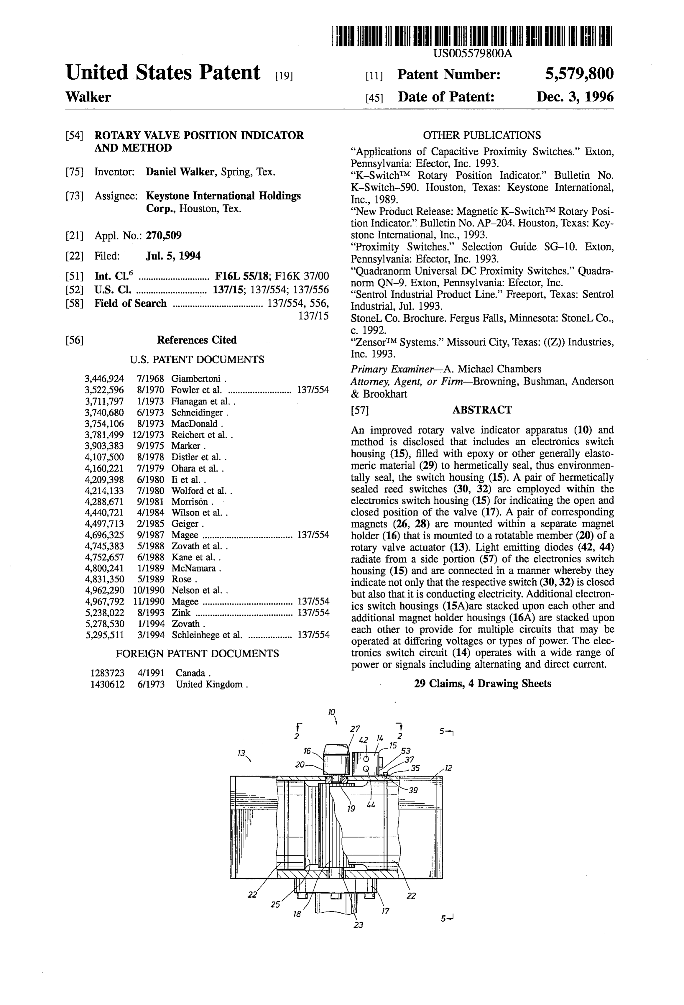
3,781,499 12/1973 Reichert et al.. An improved rotary valve indicator apparatus (10) and 3,903,383 9/1975 Marker. method is disclosed that includes an electronics switch 4,107,500 8/1978 Distler et al.. housing (15), filled with epoxy or other generally elasto 4,160,221 7/1979 Ohara et al.. meric material (29) to hermetically seal, thus environmen 4,209,398 6/1980 Ii et al.. tally seal, the switch housing (15). A pair of hermetically 4,214,133 7/1980 Wolford et al. . sealed reed switches (30, 32) are employed within the 4,288,671 9/1981 Morrison. electronics switch housing (15) for indicating the open and 4,440,721 4/1984 Wilson et al. . closed position of the valve (17). A pair of corresponding 4,497,713 2/1985 Geiger. magnets (26, 28) are mounted within a separate magnet 4,696,325 9/1987 Magee ..................................... 37A554 holder (16) that is mounted to a rotatable member (20) of a 4,745,383 5/1988 Zovath et al.. rotary valve actuator (13). Light emitting diodes (42, 44) 4,752,657 6/1988 Kane et al. . radiate from a side portion (57) of the electronics switch 4,800,241 1/1989 McNamara. housing (15) and are connected in a manner whereby they 4,831,350 5/1989 Rose. indicate not only that the respective switch (30,32) is closed 4,962,290 10/1990 Nelson et al. . but also that it is conducting electricity. Additional electron 4,967,792 11/1990 Magee ..................................... 137,554 ics switch housings (15A)are stacked upon each other and 5,238,022 8/1993 Zink ... ... 37,554 additional magnet holder housings (16A) are stacked upon 5,278,530 1/1994 Zovath. each other to provide for multiple circuits that may be 5,295,511 3/1994 Schleinhege et al. .................. 137,554 operated at differing voltages or types of power. The elec FOREIGN PATENT DOCUMENTS tronics switch circuit (14) operates with a wide range of
power or signals including alternating and direct current.
1430612 6/1973 United Kingdom. 29 Claims, 4 Drawing Sheets
Page 2
Drawing sheet — no readable text.
Page 3
Drawing sheet — no readable text.
Page 4
Drawing sheet — no readable text.
Page 5
Drawing sheet — no readable text.
Page 6
ROTARY VALVE POSITION INDICATOR the valve actuator assemblies is often cumbersome and AND METHOD difficult because it requires threading and tightening of numerous small screws or nuts. The metallic construction of many switches eventually results in corrosion that causes the
BACKGROUND OF THE INVENTION 5 switch installation to physically seize up, weaken or come 1. Field of the Invention loose, leak, or otherwise operate in an undesirable manner.
Heavy valve switch boxes are expensive and require
This invention relates generally to an electrical apparatus considerable ongoing maintenance. Because the switch indi for remote monitoring of a rotary valve position. More cators are large, bulky, and clumsy, they are difficult to specifically, this invention relates to an improved construc 10 manufacture and have tended in the past to spawn many tion of a rotary valve position indicator. different non-standardized brands that may have to be used 2. Description of the Background in a single system. Switch packages are typically cumber Remote monitoring and control of flow systems having some in that two separate packages must be used to provide numerous valves is often provided by computers using an open position switch and a closed position switch. specialized software. An electrical valve position indicator 15 The power supplied to some valve position indicators, may be used with each monitored valve to provide a signal especially those that use inductive or capacitive proximity to the system control computer. Generally, the signal pro detectors, requires precise voltage specifications and cannot vided by a valve position indicator is indicative of a status be used without modification for both alternating and direct condition of the particular valve, such as whether the valve current power. Power fluctuations may cause false signals to is fully open, fully closed, partially open, and so forth. 20 be produced in such valve position indicators to thereby Electrical devices that have been used in the past to deleteriously affect the computer control system. perform this function have had numerous problems. For As well, valve position indicators are typically sensitive instance, the switch indicators available to monitor valves to load variations. For instance, a valve position indicator must be sturdy and so are often supplied in large, bulky designed for use with an inductive load may cause system housings that have numerous crevices, dead end holes, and 25 problems when used with a solid state load. A solid state other irregularities. Such devices often tend to collect dirt in valve position indicator that is required to even momentarily the cracks and crevices and so are not suitable for operation switch a load outside its tolerances will often fail. in food processing environments, such as breweries, that Consequently, there remains the need for an improved require a high degree of cleanliness. rotary valve indicator that offers dependable operation at The electrical switches used in these bulky indicators 30 reduced levels of capital investment, is compact, is easily often have "bounce' problems that may produce false sig cleaned, handles small power signals without contact nals in a control system. Furthermore, the switch contacts in bounce problems, operates reliably even with wide power such devices are often affected by moisture or other factors fluctuations and different types of loads, provides hermeti so that even if the contacts close properly, they may still cally sealed switch contacts, is rugged and reliable, is have too much contact resistance to allow proper electrical 35 submersible and explosion proof, is easily mounted, requires signal flow. This may be especially true for relatively low little maintenance and is of such low cost that it can be amperage signals associated with solid state automation thrown away if failure occurs. Those skilled in the art have control systems. Such problems may cause system operation long sought and will appreciate the present invention, which errors by producing false or intermittently faulty signals. 40 provides solutions to these and other problems. Even sealed contacts may eventually develop contact SUMMARY OF THE INVENTION resistance problems. Due to the weather-proof or explosion proof housings of electrical contact boxes, it is difficult and Therefore, an object of the present invention is to provide time-consuming for an operator to check whether a fault an improved rotary valve position indicator. condition is the result of the contacts being closed but not 45 Another object of the present invention is to provide for conducting, or whether the contacts failed to close alto local visualization of contact operation. gether, or whether the electrical problem lies somewhere in Yet another object is to provide a smaller and less the cabling or interconnections. Once the housing is complex switch position indicator that is insensitive to a removed, the contact box is no longer explosion-proof and wide range of power fluctuations and operates with either activation of a switch during checking or maintenance could 5O alternating or D.C. power.
ignite flammable or explosive vapors. Yet another object is to provide a valve position indicator As well, electrical connections to the housings are often that is unaffected by moist or even submersed operating difficult and time-consuming to complete because they conditions.
require disassembly of covers or lids from their respective Yet another object is to provide a switch package that will bases. If the cover or lid is not properly reassembled, then 55 not create any sparking or arcing, even under maintenance leakage eventually occurs that may cause system problems. circumstances, in an explosive atmosphere. In some cases, electrical cable conduits go through various A feature of the present invention is a rotating magnet ambient temperature conditions that cause them to gradually holder housing separate from an electronics switch housing. fill with condensation that eventually makes its way back
An advantage into otherwise weatherproof switch housings. Weather-proof 60 an improved product.of the present invention is reduced costs for switches may not be adequately sealed when the switch housings are flushed with fluids or submersed as could Another advantage of the present invention is reduced happen when a plant is being cleaned. user costs because maintenance costs are decreased by using Furthermore, heavy and bulky valve position indicators, throwaway device logic.
though sturdy, may be easily broken or damaged if dropped, 65 Yet another advantage of the present invention is to or due to corrosion, or due to leakage in the switch indicator provide end of travel indicators for both open and closed housings. The mounting of the switch indicator devices to valve positions in a single switch housing.
Page 7
The present invention provides for an indicator assembly DETAILED DESCRIPTION OF THE to indicate a valve position of a rotary valve element. The PREFERRED EMBODIMENTS rotary valve element is rotatable by an actuator assembly The present invention provides generally for an improved that is typically disposed in an actuator assembly housing.
The actuator assembly includes a rotational element that rotary valve position indicator and method. The rotary rotates along with the rotary valve element to open and close position indicator of the present invention is preferably the valve. The indicator assembly includes a magnet holder characterized by its separation of magnet holder housing and attached to the rotational element of the actuator assembly electric switch circuitry. This construction produces two housings, with a magnet disposed in the magnet holder for rotation built into the rather than one housing with a rotatable portion housing as is seen in prior art rotary position along with the rotary valve element. An electronic switch 10 indicators. The result is an indicator assembly with two housing is also mounted to the rotary actuator housing smaller and more convenient overall size housings, sturdier adjacent to the magnet holder so that the rotary actuator construction, and uncomplicated operation. Those skilled in housing independently supports the electronic switch hous the art will immediately appreciate that the present invention ing and the magnet holder, respectively, at a selected dis is a great improvement over prior art rotary valve position tance therebetween. The electronic switch housing includes 15 indicators. The preferred separate mounting of a rotary a reed switch therein that is responsive to rotation of the magnet holder housing from the electronics control box magnet for indicating a position of the rotary valve element. effectively eliminates those problems associated with rotat In a preferred embodiment, the electronic switch housing ing components within a single housing. In fact, the rela may be connected to the actuator housing by a fastener, such tively simple improvement of placing the magnets and as a threaded fastener. The electronic switch housing is open 20 switches in separately mounted housings produces numer to ambient conditions associated with the valve. Light ous surprising advantages, as discussed hereinafter, that emitting diodes are preferably electrically connected to the provide solutions to many problems that have plagued prior outputs of the reed switches so as to provide a readily art valve position indicators.
obtained local verification that the switch is not only closed, With reference now to the drawings, and more specifically but that it is also conducting. 25
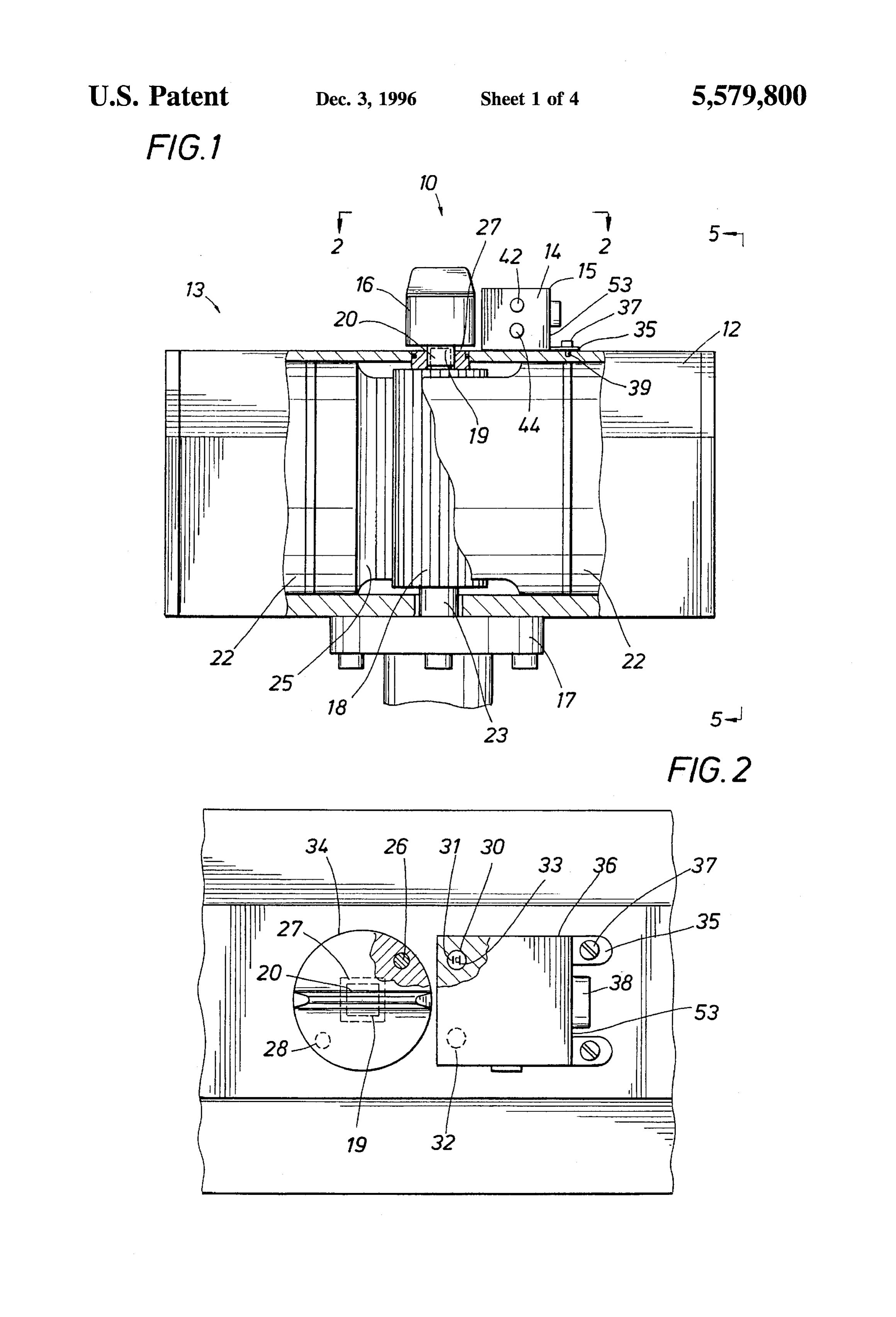
In operation, at least two magnets are preferably provided to FIG. 1, there is shown a position indicator assembly 10, in the magnet holder. The magnet holder is connected to the mounted to valve actuator housing 12 of actuator 13. Posi rotational element of the rotary actuator. The electronic tion indicator assembly 10 includes electronic switch 14 and magnet holder 16.
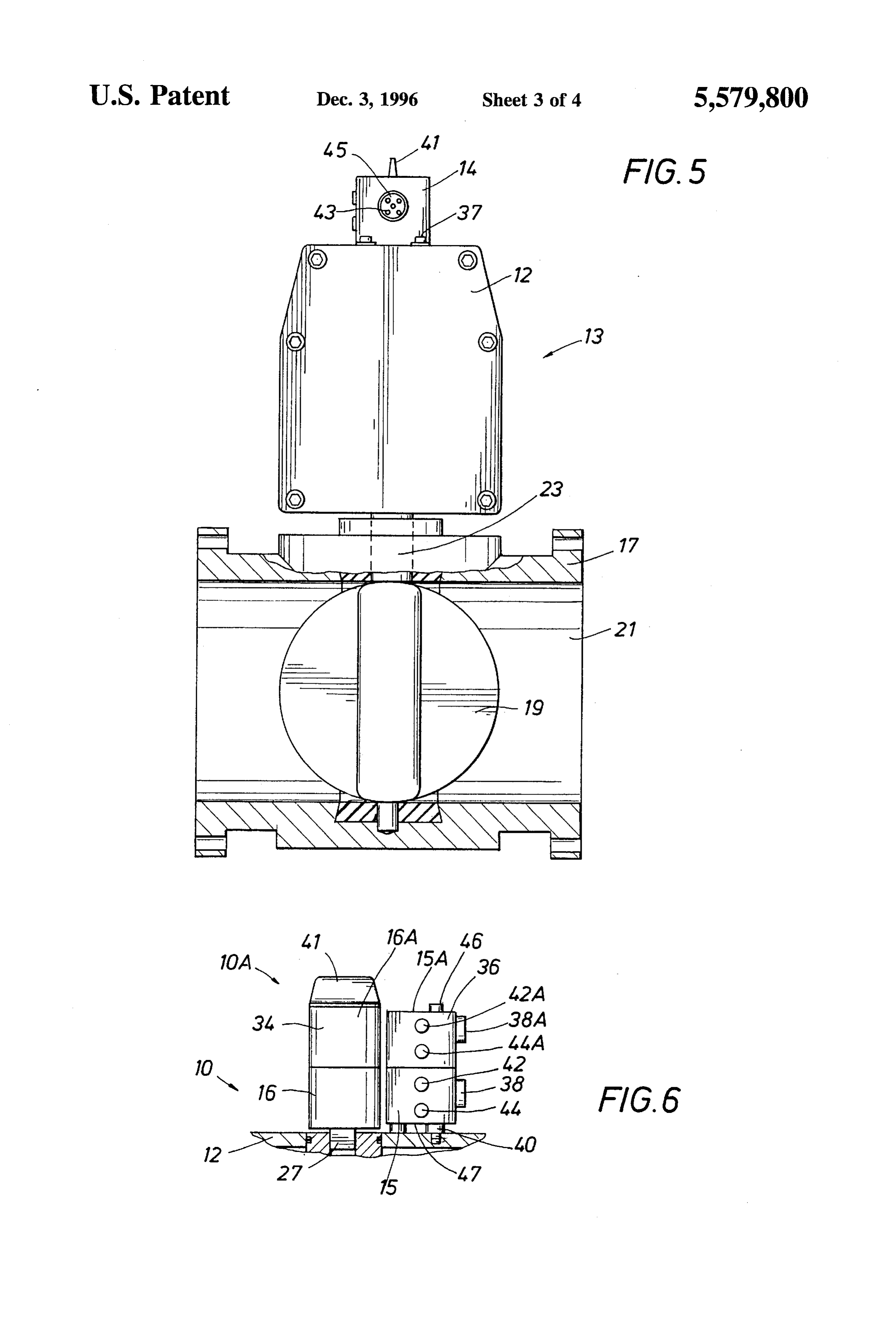
switch housing may be sealed with epoxy or other electri cally nonconductive sealing material. Each magnet indepen 30 Valve actuator housing 12 is mounted to rotary valve 17 dently operates a respective reed switch. The electronic (see FIG. 5). Rotary valve 17 includes rotary valve element switch housing is mounted to the actuator housing indepen 19 that rotatably moves between an open and a closed dently of the magnet holder. As the actuator is activated, the position to control fluid flow through bore 21. Rotary magnets operate the reed switches to indicate the open or actuator 13 may be electrically, pneumatically, manually, or closed position of the valve. 35 otherwise powered, for rotary movement of rotary valve Other features and intended advantages of the present element 19. In FIGS. 1, 2, and 5, rotary actuator 13 is of the pneumatic type, with pneumatic pistons 22 having racks 25 invention will be more readily apparent by reference to the secured thereto for engaging and rotating pinion 18 to open following detailed description in connection with the accom and close rotary valve 17. Actuator shaft 20 is rotatable and panying drawings.
40 is preferably connected, directly or indirectly, to rotary valve
BRIEF DESCRIPTION OF THE DRAWINGS shaft 23 that rotates rotary valve element 19. Magnet holder FIG. 1 is an elevational view, partially in section, of a housing 16 is mounted on actuator shaft 20 of rotary actuator 13 and rotates therewith. Therefore, magnet holder housing rotary valve indicator mounted to a valve actuator in accord 16 also rotates in concert with rotary valve shaft 23 and with the present invention; 45 corresponding rotary valve element 19. FIG. 2 is an upper view, partially in section, of the rotary Magnet holder housing 16 preferably contains two mag valve indicator of FIG. 1 along the line 2-2, nets 26 and 28, each producing a magnetic field, that are FIG. 3 is an elevational view, partially in section, of an used to indicate the open and closed positions of valve 17. alternative embodiment rotary valve indicator; Magnets 26 and 28 may be arranged in various configura FIG. 4 is an elevational view, partially in section, of the 50 tions, as desired, to activate reed switches 30 and 32, which switch housing of FIG. 3 along the line 4-4; are correspondingly arranged to most suitably receive the FIG. 5 is an elevational view, partially in section, of the respective magnetic fields of the magnets. While magnets 26 rotary valve indicator of FIG. 1 along the line 5-5; and 28 are preferably mounted within substantially cylin FIG. 6 is an elevational view, partially in section, of 55 drical magnet holder housing 16, they could also be on arms (not shown), in a disc (not shown) that could rotate above stacked switch housings and magnet holders; switch housing 15, or in numerous other configurations as FIG. 7 is a schematic for an electronic switch in accord desired.
with the present invention; and The relative position of the magnets 26 and 28 with FIG. 8 is an alternative embodiment schematic for an respect to reed switches 30 and 32, and more particularly electronic switch in accord with the present invention. 60 switch contact elements 31 and 33, shown with respect to While the present invention will be described in connec reed switch 30, determine the degree of rotation of valve tion with presently preferred embodiments, it will be under element 19 at which reed switches 30 and 32 open and close. stood that it is not intended to limit the invention to those Because the switches of the present invention are magnetic embodiments. On the contrary, it is intended to cover all and have no wear, the particular point of opening and closing alternatives, modifications, and equivalents included within 65 during rotation of valve element 19 does not change due to the spirit of the invention and as defined in the appended electrical variations or mechanical wear that occurs in other claims. switches. The operating repeatability of opening and closing
Page 8
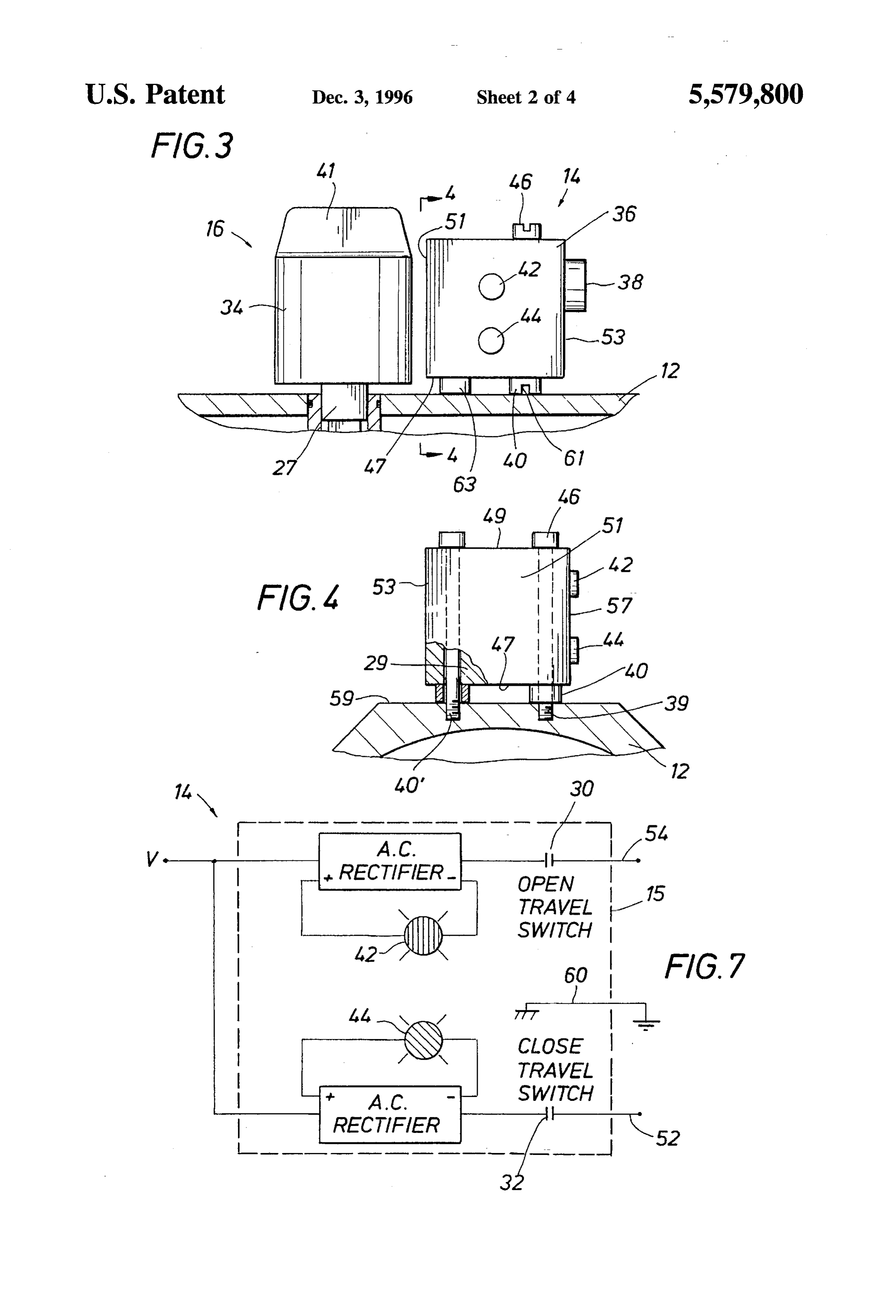
of the switches, with respect to position of the valve, stays Switch housing 15 and magnet holder 16 are clearly not within about plus or minus one-half degree. An adjustment held together by a larger housing or interconnected structure mechanism (not shown) may be used herewith to adjust the as used in the prior art, but are separately and independently particular valve angle at which the opening and closing of mounted and supported by actuator 13. The magnet-reed the switches occurs. switch spacing between switch housing 15 and magnet The magnets 26 and 28 are preferably of the rare earth holder 16 is normally fixed at the desired optimal spacing by type so as to provide relatively constant magnetic field the positioning of threaded mounting holes 39 in outer strength over a long period of time, although other types of surface 59 of actuator housing 12 (see FIG. 4). Thus, no suitably long-lasting magnetic material could also be used. adjustments are normally required. However, the mounting With long-lasting magnets, the reed switches are reliably 10 bracket 35, stand-offs 40, or mounting holes 39, or mounting operated in a stable manner over a long period of time, so method could be reconstructed or designed for a different that there is no significant signal timing variation due, for magnet-reed switch spacing.
instance, to aging of the magnet. Magnets 26 and 28 may be Because electronics switch 14 is small and effectively encapsulated, if desired, to reduce the possibility of any includes no moving parts, switch box. 15 is easily sealed if corrosion that could affect magnet strength. In a presently 15 desired, as by filling with epoxies or other nonconducting preferred embodiment, magnet housing 16 has a substan materials. Therefore, electronic switch box 14 is preferably tially square or rectangular socket (or plug) mounting 27 filled with a sealing material 29, such as epoxy, elastomeric (see especially FIG. 2) that secures its position with respect material, or the like (see FIG. 4). Although reed switches 30 to the preferably square or rectangular end portion 19 of and 32 contain movable contact elements 31 and 33, the actuator shaft 20. contact elements are hermetically sealed so that the switches Switch housing 15 may be mounted to actuator housing 20 are conveniently epoxied in place if desired. 12 with brackets 35 and screws 37 at threaded mounting To maintain switch tolerances, it is desirable that the holes 39. Alternatively, switch housing 15 may be mounted magnets and switches be securely mounted, within the on stand-offs 40 with threaded bolts 40 (see FIGS. 3, 4, and respective switch housing 15 and magnet holder housing 16, 6). Bolts 40 may extend through electronics switch 14 or 25 in a manner that will not change due to vibration or even may be accessible through an aperture through the housing. severe shocks such as if switch housing 15 or magnet Blank stand offs 63 do not have a bolt therethrough but are housing 16 is dropped during, for instance, transport or preferably molded onto switch housing 15 for additional assembly. Because housings 15 and 16 are preferably filled support. The mounting stand offs 40 preferably have weep with epoxy or other such material, secure mounting of the slots 61 therein. Weep slots 61 allow any liquid which may enter at the head of securing bolts 40 to flow out or evaporate 30 invention.and switches
This magnets is not a problem in the present sturdy mounting provides a great advantage rather than become trapped so as to produce mold or over prior art assemblies that normally cannot be dropped or bacteria. This latter mounting method may be preferred for otherwise experience significant g-shock and/or extensive valve operation in sterile environments where surfaces are vibration without damage or calibration variations. preferably exposed to the ambience so they can be more easily cleaned. A sterile environment in which such a 35 To further enhance electronics switch 14 sealing, it is mounting may be desired could, for instance, include a possible to include a preferred embodiment connector socket brewery with an automated valve system. 38 therewith, which may conveniently include five pins 43 As discussed briefly hereinbefore, Applicant preferably (see FIGS. 2, 3, 5, and 6) and have a sealed socket interior mounts the magnets separately from the reed switches in a portion 45, to prevent condensation from reaching the inte separate magnet holder housing 16 and electronics switch 14 40 rior of switch box 15. If switchbox 15 is filled with epoxy because such a configuration results in surprisingly numer sealing, such condensation would not reach any operating ous benefits. This separate construction results in less com components even without a sealed socket interiorportion 45. plex, smaller, more compact, sturdier, and more easily Connector socket 38 may also be of the type that is used with mounted components. This simple construction avoids the a flange-type plug (not shown), such as a connector assem problem of cracks and crevices that can collect debris, as is 45 bly available from Brad Harrison or other connector manu facturers, that quickly and securely provides a good electri undesirable in a sterile environment, because the separate electronics switchbox 15 and magnet housing 16 are easily cal connection. Other connections may also be used. For formed with smooth walls, such as smooth walls 34 and 36 instance a conduit (not shown) may be installed directly to on the switch box and magnet housing, respectively. While connector 38 without a sealed interior portion 45 but having magnet housing 16 and switch box housing 15 have the 50 several feet of leads extending therefrom to be threaded shape herein disclosed, they could have other shapes as through the conduit. The sealed switch housing 15 remains desired. water tight. As well, because switch housing 15, including Mounting wall 47 may for some purposes be preferably switches, L.E.D.'s, and circuitry, is completely filled with raised by stand-offs 40 and 63 so as to allow easy, unob epoxy, the present invention is effectively explosion-proof so as to be useable in areas which become filled with structed cleaning when necessary for a sterile environment. 55 explosive or highly flammable vapors.
Asmoothly raised elongate portion 41 on magnet housing 16 may be used to visually indicate whether valve 24 is open or Open indicator 42 and closed indicator 44 provide a visual closed. Preferably switch box 15 is box-like and has six indication of whether a respective reed switch 30 or 32 is sides 47,49, 51, 53, 55, and 57. The mounting is preferably activated. For instance, with reference to FIG. 7, which made using just one side of switch box 15 to prevent the 60 shows a simplified schematic diagram of the circuit of formation of unnecessary cracks and crevices during the switch 14 within switch housing 15, open indicator 42 will light mounting. As shown, lower side 47 is used in FIG.3 and an activated when corresponding reed switch 30 is magnetically outer side 53 is mounted with brackets 35 in FIG. 2. Thus, to make contact by a corresponding magnet. Open the remaining sides are connected to actuator housing 12 and closed indicators 42 and 44 are preferably L.E.D.'s only by virtue of their connection to switch box 15 and not 65 (light emitting diodes).
due to other external connecting members that form addi In operation of the electronic circuit of switch 14 shown tional cracks and crevices. in FIG. 7, voltage from a power source or signal source V
Page 9
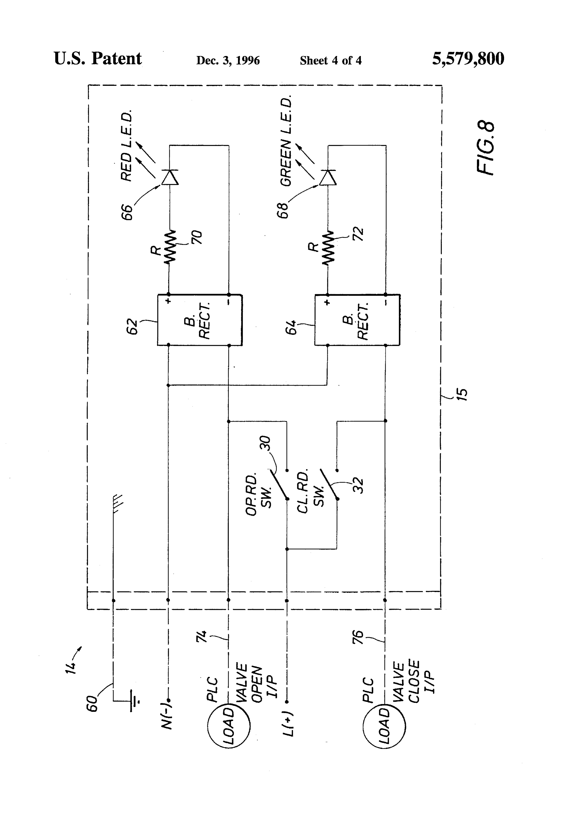
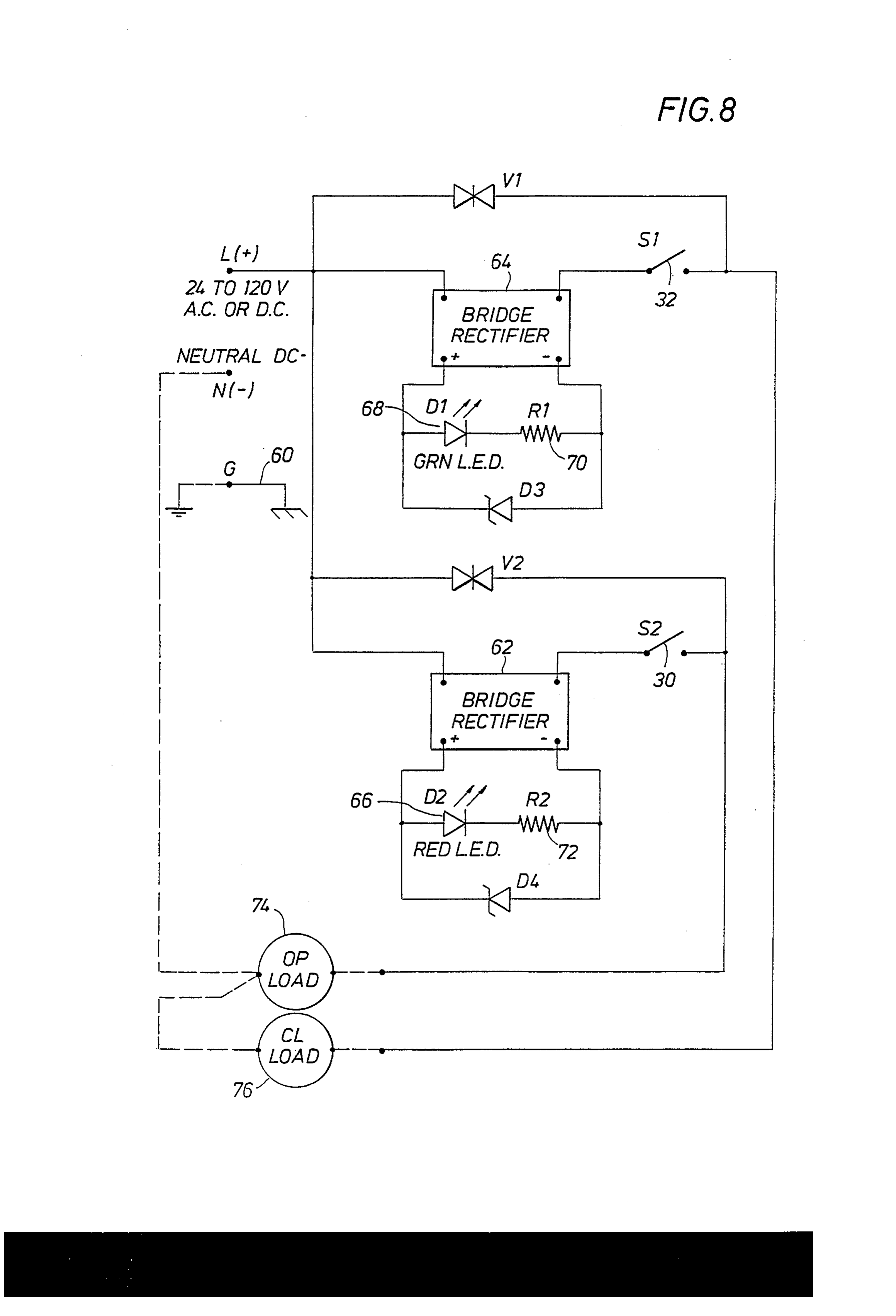
is applied to reed contacts of reed switches 30 and 32. When and 32, as well as respective bridge rectifiers 62 and 64, rotary valve element 19 is in a closed position, contacts of from damaging back emfs that occur as the switches open reed switch 32 will close to connect light 44 to control to thereby interrupt supply to an inductive load such as a devices (not shown) and activate light 44. Voltage V is also relay coil and the like. Resistors 70 and 72 limit current to applied to output line 52 to indicate that valve 17 is closed. respective L.E.D.'s to prevent damage and promote long Reed switch 30 is open so that light 42 is off and output line life. Switches 30 and 32 function to indicate that rotary 54 is de-energized. As rotary valve element 19 moves from element 19 is, respectively, open or closed. Output lines the closed position to the open position, both lights and provide the status information, as determined by the position output lines will be disconnected from voltage V, and the computer system will sense the valve is moving. When 10 of switches 30 and 32, to the open and closed loads 74 and 76, respectively, applied by the control system.
rotary valve 19 moves to the open position, light 42 is on and In operation, a respective normally open reed switch will output line 54 is connected to voltage V. close at the end of valve actuator 13 travel to allow current Reed switches 30 and 32 have small contact mass and therefore are not likely to produce contact "bounce' that load i.e. This to flow. output is used by the customer to energize a relay coil, solenoid, P.L.C. input, and the like. The could disrupt output signals to a system that may be con 15 nected to output lines 52 and 54. Furthermore, hermetically L.E.D. can only be illuminated if (1) the respective reed sealed reed switches 30 and 32 are less likely than large switch is closed, and (2) the respective reed switch is also contacts to develop contact resistance due, for instance, to conducting electricity. Thus, illumination of the L.E.D. corrosion. Contact resistance sometimes prevents otherwise tional.provides proof to service personnel that the switch is opera closed switches from conducting relatively small analog and 20 As well, red L.E.D. 66 is typically used to visually control signals that are typically between about 4 to 20 indicate an open valve and green L.E.D. 68 indicates a milliamperes. Such signals are typically greater than about closed valve.
2 milliamperes. A preferred embodiment switch may be The circuit of the present invention will operate on 6 to designed for about 25 VA. Thus, with a 24 volt AC or DC 120 volts A.C. or D.C. and even has wide operating toler power, it may provide up to about 1 ampere of current. With 25 ances with that range of operation voltage. If the A.C. line 120, volts it provide up to about 0.2 amperes of current. The or D.C. positive supply is connected to terminal point of use of reed switches in the present invention, rather than L(+), then current will flow through the full wave bridge electronic switches, allows considerably wide signal toler rectifier assuming the respective normally open reed switch ances. Reed switches can often take temporary overloads is closed. If a respective reed switch is not closed, then the whereas electronic switches normally fail immediately with 30 respective output 74 or 76 will not be driven and the an overload. respective L.E.D. cannot be illuminated. The respective load Another advantage of the circuit and configuration of the will also see a very high impedance when the switch is open present invention is that the L.E.D.'s are connected in a because the impedance of the varistors, V1 and V2, is manner that not only determines the status of the valve but normally very high as discussed hereinafter. also indicate that the relevant switch is closed and actually 35 If valve actuator 13 is run fully open or closed, then a does conduct the small signal levels that are also used to respective of magnets 26 and 28 in magnet holder 16 will be activate the L.E.D.'s. Thus, a technician can readily deter rotated into the appropriate reed switch magnetic activation mine, without having to open a sealed enclosure and perform field. The selected switch will close its contact and drive the current checks, whether the switch is functioning correctly-a customer's load device, and the respective rectifier will job that is difficult and time-consuming. Small analog and therefore have current flowing through it and will produce a control signals are typically about 4 milliamperes and nor D.C. voltage supply on its terminals. The respective Zener mally not larger than about 200 milliamperes, although reed diode will shunt off voltage and hold a steady value across switches may have a significantly greater current carrying the L.E.D. branch circuit. A respective of resistors 70 and 72 ability. is placed in series with each L.E.D. to limit the current flow Another presently preferred circuit embodiment for elec 45 through the L.E.D. within its design parameters. tronic switch 14 is shown in FIG. 8. Voltage L(+), which is Varistors V1 and V2 are located in the circuit across the typically a system voltage, may be either direct current or respective bridge rectifiers and reed switch contacts. The alternating current and will typically range from 24 to 120 varistors have no effect on the circuit (very high impedance) volts A.C. or D.C. As well, the circuit of FIG. 8 will work provided that the voltage potential does not exceed the for wide tolerances in voltage L(+). Thus, the circuit of FIG. 50 respective varistor rating. However, if a voltage spike 8 has significant advantages over many proximity detector appears in the line, or the switch opens to de-energize an circuits that require a fairly close tolerance voltage L(+). inductive load i.e. a relay coil, then the resultant back emfs Typical values for operating voltage L(+) of the present damaging effect on the contact and bridge rectifier will be embodiment may be 24 volts up to 120 volts AC or DC, with minimized. The varistor's ability to clip-off dangerous a wide tolerance for these voltages. The wide range of 55 power spikes also minimizes the magnitude of any arcing possible supply voltages do not adversely affect operation of that occurs when switch contacts break an energized circuit, either the switches or the L.E.D.'s. L(+) is applied with thus prolonging contact life. In this manner, the varistors respect to N(-), which may be a circuit ground, common, provide over-voltage and back emf protection to the system ground value, chassis ground, or could be a negative switches.
voltage, and so forth. Ground may also be applied by ground 60 In summary, the present circuitry is usable with a wide line 60. The dashed lines shown in FIG. 8 generally repre range of supply voltages and types of loads, includes a sent field wiring external to switch housing 14. self-test L.E.D. that eliminates questions of switch operation Bridge rectifiers 62 and 64 provide that either alternating to reduce service time, and is sealed in a rugged, waterproof, current or direct current will activate respective L.E.D.'s 66 explosion-proof package.
and 68. Zener diodes D3 and D4 are parallel with respective 65 With reference now to FIG. 6, yet another feature of the L.E.D.'s to ensure a constant voltage even with quite wide present invention is shown that allows for multiple circuits variations in power. Varistors V1 and V2 protect switches 30 operating at different voltages. For instance, an emergency
Page 10
shutdown circuit may be connected to switch indicator 10A, a light-emitting diode physically included with said and the computer control system could be connected to switch housing and electrically connected to said reed switch indicator 10. Each system could operate at separate switch operable for providing a visual signal when said voltages. However, closed and open signals at those separate reed switch is conducting electricity. voltages would be available by the stacked switch boxes 15 8. The apparatus of claim 7, wherein: and 15A operated by respective stacked magnet holders 16 said switch housing comprises a substantially solid body and 16A. Other respective features discussed earlier are of nonconducting material. referred to with an "A" suffix. The size and shape of the 9. The apparatus of claim 7, wherein all surfaces of said housings of the present invention are very suitable for such switch housing are substantially smooth. stacking, which may be used to provide two or more circuits 10 10. The apparatus of claim 7, further comprising: attached to a single actuator housing 12. a second magnet carried by said magnet holder; and The foregoing disclosure and description of the invention a second reed switch internally of said switch housing, is illustrative and explanatory thereof, and it will be appre said second reed switch being responsive to said second ciated by those skilled in the art that various changes in the magnet to indicate a second position of said rotary size, shape, positioning, and materials, as well as in the valve element.
details of the illustrated construction or combinations of 15 features of the various elements, may be made without 11. A valve position indicator for operation with an departing from the spirit of the invention. actuator, said actuator including an actuator housing with an What is claimed is: outer surface, said actuator further including an actuator 1. A method for indicating a position of a rotary valve assembly for rotating a rotary valve element, said actuator element, comprising the following steps: 20 assembly having a rotational element rotatable with said providing at least two reed switches within a switch rotary valve element, said valve position indicator compris housing, each of said two reed switches being inde ing:
pendently operable by first and second magnetic fields; a first electronic switch comprising a first switch housing providing at least two magnets within a first magnet removably mounted on said outer surface of said actua
tor housing and substantially filled with an electrically mounting said first magnet holder to a rotational element nonconductive material, said first electronic switch of a rotary actuator, further including:
independently removably mounting, with respect to said a first reed switch internal of said first switch housing magnet holder, said switch housing to a different por with first conductors leading to said first reed switch, tion of said rotary actuator; and said first reed switch being responsive to a first 30 magnetic field to provide an indication of a first providing a smooth outer surface on said switch housing valve position, and and providing a separate smooth outer surface on said first magnet holder. a fastener member extending from said first switch 2. The method of claim 1, further comprising: housing and connecting to said outer surface of said selectively supplying either alternating current or direct 35 actuator housing for removably securing said first current to said switch housing. switch housing to said actuator housing; and 3. The method of claim 1, further comprising: a first magnet external to said switch housing and mov stacking a second magnet holder on top of said first able with said rotational element, said first magnet magnet holder. producing said first magnetic field. 4. The method of claim 2, further comprising: 12. The valve position indicator of claim 11, further 40 comprising:
connecting a light-emitting diode to each of said reed switches in a manner that each said respective light a magnet holder external of said first switch housing for emitting diode is activated when a respective said reed carrying said first magnet, said magnet holder being switch is conducting said selected direct or alternating independently carried, with respect to said first switch Current.
housing, by said actuator at a selected distance from 5. The method of claim 1, further comprising: said first switch housing.
each of said two reed switches being mounted along one 13. The valve position indicator of claim 11, further substantially flat wall of said electronics circuit box. comprising:
6. The method of claim 1, further comprising: a second magnet carried by said magnet holder, hermetically sealing said switch housing. a second reed switch internal of said first switch housing 7. An apparatus for indicating the position of a rotary 50 for cooperation with said second reed switch, said valve element, said rotary valve element being rotatable by second reed switch and said second magnet operating an actuator, said actuator including an actuator housing and separately from said first magnet and said first reed having a rotational element rotatable with said rotary valve switch to indicate a second position of said rotary valve element, said apparatus comprising: element.
a magnet holder attached to and rotatable with said 55 14. The valve position indicator of claim 11, further rotational element, a magnet carried by said magnet comprising:
holder for rotation therewith; a second electronic switch comprising a second switch an electronic switch assembly comprising a switch hous housing stacked upon said first switch housing, said ing separate from said actuator housing and removably 60 second electronic switch further including: mountable to said actuator housing adjacent to said a second reed switch internal to said second switch magnet holder such that said actuator housing indepen housing, said second reed switch operating in con dently supports said switch housing and said magnet junction with said first reed switch for indicating said holder, respectively, at a selected distance therebe first valve position, said second reed switch having tween, said switch assembly including a reed switch second conductors leading to said second reed switch internally of said switch housing responsive to rotation 65 for providing a separate switch circuit. of said magnet for indicating a position of said rotary 15. A valve position indicator for operation with an valve element; and actuator, said actuator including an actuator housing with an
Page 11
outer surface, said actuator further including an actuator said electronic switch housing is substantially filled with assembly for rotating a rotary valve element, said actuator a nonmetallic substance.
assembly having a rotational element rotatable with said 23. The valve position indicator of claim 20, wherein: rotary valve element, said valve position indicator compris said electronic switch housing is substantially box-like, ing: having a first side connected to said actuator housing an electronic switch comprising a switch housing Sub and a second side opposite from said first side, said stantially filled with a nonmetallic material for sealing light source being mounted on an intermediate side of said switch housing, said switch housing having first said electronic switch housing between said first and and second sides, a fastener for removably securing second sides.
said first side of said switch housing to said outer 10 24. The valve position indicator of claim 23, further surface of said actuator housing, said second side of comprising:
said switch housing being unattached to said actuator except through said first side, said electronic switch a second magnet carried by said magnet holder for further comprising a reed switch internal to said switch producing a second magnetic field, housing, said reed switch being responsive to a first 15 a second reed switch internal to said switch housing magnetic field to provide an indication of a valve responsive to said second magnetic field, and position; and a second light source for indicating that said second reed a first magnet external to said switch housing and mov switch is conducting electricity. able with said rotational element, said first magnet 25. A valve position indicator operable with alternating producing said first magnetic field. current or direct current, said valve position indicator being 16. The valve position indicator of claim 15, wherein: 20 operable with an actuator including an actuator housing, said said first and second sides are opposite sides of said actuator further including a rotary actuator assembly having switch housing. a rotational element, said valve position indicator compris 17. The valve position indicator of claim 16, wherein: ing:
said electronics switch housing is substantially box 25 an electronics switch comprising a switch housing shaped and includes a third side between said first and secured to said actuator housing, said electronics second sides, said third side being unconnected to said switch further comprising:
actuator except through said first side. a connector to said switch housing having an input 18. The valve position indicator of claim 17, further power line for receiving said alternating current or comprising: direct current, said connector having open and closed a light-emitting diode disposed on said third side for 30 outputs for respective open and closed valve position providing a visual indication that said reed switch is signals, said connector having a common line for conducting electricity. said input power line, 19. The valve position indicator of claim 15, wherein: first and second reed switches each having a contact said electronics switch housing is substantially box 35 electrically connecting to respective of said open and shaped and said first and second sides are adjacent each closed output lines, said first and second reed other. switches each being separately operable responsive 20. A valve position indicator for indicating a position of to first and second magnetic fields, a rotary valve element, said valve position indicator being first and second lights to radiate from said switch operable with an actuator including an actuator housing, said housing responsively to respective of said first and actuator further including an actuator assembly within said 40 second reed switches, said first and second lights actuator housing for rotating said rotary valve element, said being electrically connected to said common input actuator assembly having a rotational element rotatable with power line and said open and closed output lines said rotary valve element, said valve position indicator through respective of said first and second switches; comprising: and an electronic switch comprising a switch housing separate 45 first and second rectifiers for supplying direct current to from said actuator housing and removably mountable said first and second lights from either alternating to said actuator housing, said electronic switch further current or direct current; and including: a magnet holder housing mounted to said rotational a first reed switch internal to said switch housing for element, said magnet holder carrying first and second indicating a position of said valve, 50 magnets to produce said first and second magnetic a first light source supported by said electronic switch fields.
housing and externally visible from said electronic 26. The valve position indicator of claim 25, further switch housing for indicating that said first reed comprising:
switch is conducting a control signal less than 25 VA, first and second resistors for limiting direct current to said and 55 first and second lights.
an electrical connection between said first reed switch 27. The valve position indicator of claim 26, wherein said and said first light source; and first and second lights comprise light-emitting diodes. a first magnet movable with said rotational element, 28. The valve position indicator of claim 25, wherein said said first magnet producing first magnetic field. magnet housing is external to and independently mounted 21. The valve position indicator of claim 20, further 60 with respect to said switch housing.
comprising: 29. The valve position indicator of claim 25, further a magnet holder mounted to said rotational element of comprising:
said actuator housing for carrying said first magnet, a first and second varistors connected in parallel to said said magnet holder housing being external to said first and second switches and said first and second switch housing and supported by said actuator housing 65 rectifiers.
independently from said switch housing.
22. The valve position indicator of claim 20, wherein:
Page 12
UNITED STATES PATENT AND TRADEMARK OFFICE
CERTIFICATE OF CORRECTION
PATENT NO. : 5,579,800 Page 1 of 2
NVENTOR(S) : Daniel Walker It is certified that error appears in the above-indentified patent and that said Letters Patent is hereby Corrected as shown below:
Replace Fig. 8 with the attached Fig. 8.
Signed and Sealed this
Twenty-second Day of April, 1997 (a teen BRUCE LEHMAN
Commissioner of Patents and Trademarks Attesting Officer
Page 13
Drawing sheet — no readable text.
Provenance
- Collection
- Cited prior art
- Original PDF
- patentimages.storage.googleapis.com →
- Filed
- 1994-07-05
- Pages
- 13
- Method
- pdftotext (the PDF's own text layer) + pdftoppm 300dpi page scans
- Source
- Google Patents bibliographic record
- Granted
- 1996-12-03
- Inventors
- Daniel Walker; Keystone International Holdings Corp
- Transcribed from
- patentimages.storage.googleapis.com →