patent · US2903610
Dynamo-electric machine field magnet construction with split poles
8 September 1959
Page 1
Drawing sheet — no readable text.
Page 2
Drawing sheet — no readable text.
Page 3
Drawing sheet — no readable text.
Page 4
Drawing sheet — no readable text.
Page 5
United States Patent Office 2,903,610 Patented Sept. 8, 1959
the roots of two consecutive core elements of opposed 2,903,610 polarities being connected together by a magnetic piece, DYNAMO-ELECTRIC MACHINE FIELD MAGNET So that the whole of these two core elements and of said CONSTRUCTION WITH SPLT POLES magnetic piece forms a single unit the cross section of which is substantially in the form of a horseshoe.
Pierre Etienne Bessiere, Paris, France, assignor, by mesne The manufacture of such units, either made of a single assignments, to Societe Anonyme Etablissements Lab piece or of several identical pieces juxtaposed in the inal, Paris, France, a society of the French Republic longitudinal direction (case of laminated poles), and Application July 22, 1957, Serial No. 673,344 the mounting of the inductor coils on such units are O delicate and costly operations. Furthermore, these units
Claims priority, application France August 22, 1956 must be accurately secured on a rigid supporting frame 9 Claims. (CI. 310-254) work so that their relative positions are quite correct. In order to obviate this drawback, according to the
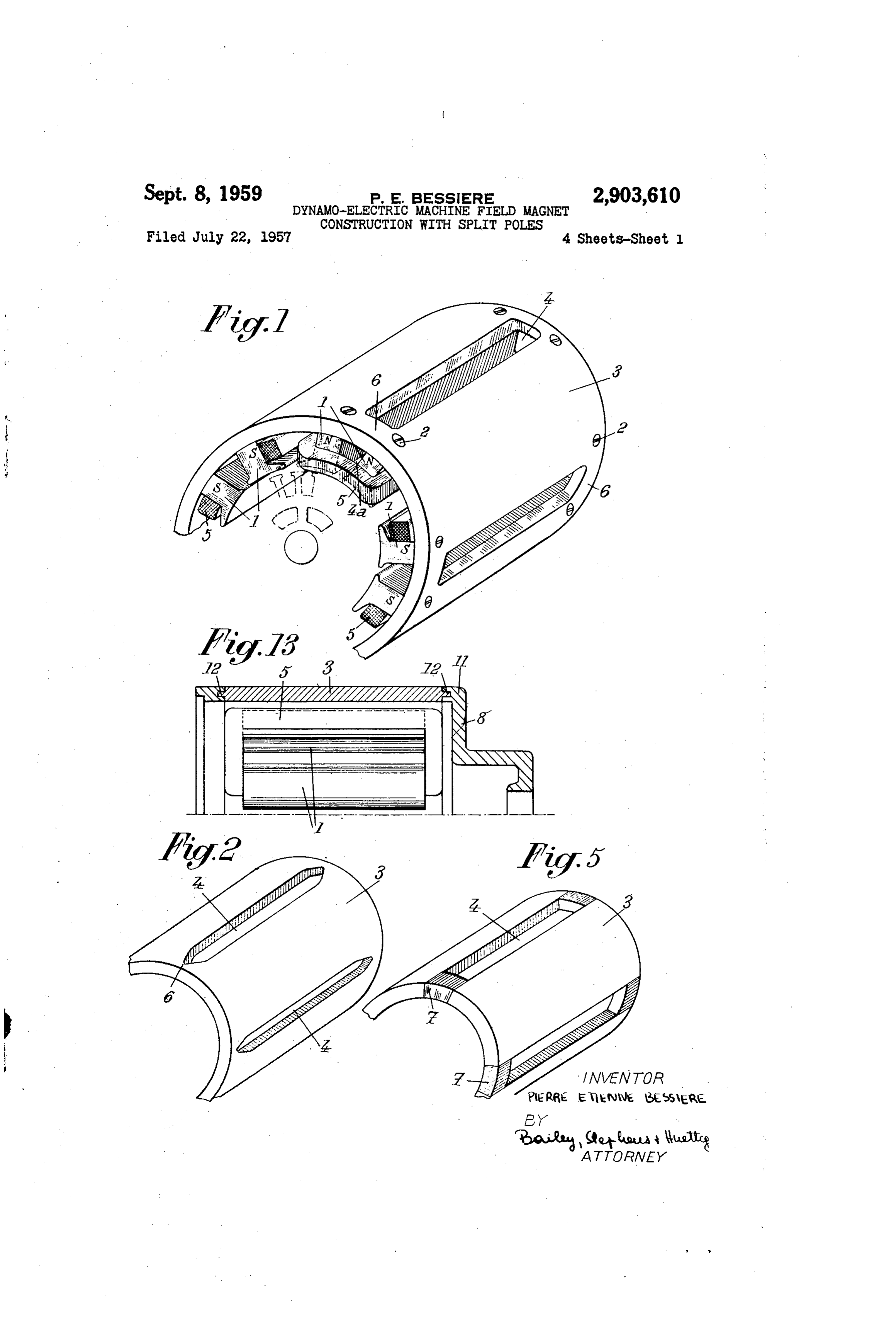
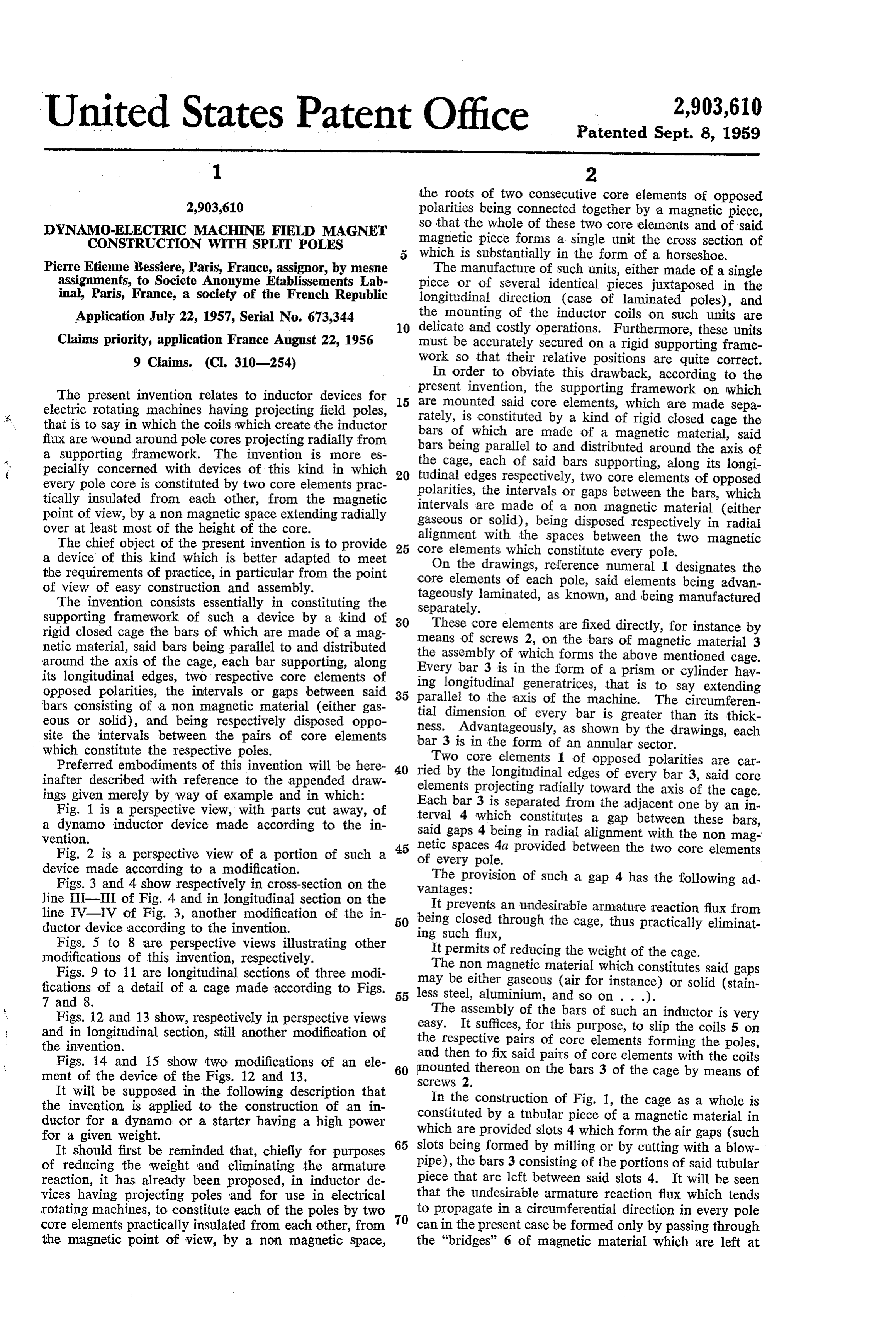
The present invention relates to inductor devices for present invention, the supporting framework on which 5 are mounted said core elements, which are made sepa electric rotating machines having projecting field poles, rately, is constituted by a kind of rigid closed cage the that is to say in which the coils which create the inductor bars of which are made of a magnetic material, said flux are wound around pole cores projecting radially from a supporting framework. The invention is more es bars the being parallel to and distributed around the axis of cage, each of said bars supporting, along its longi pecially concerned with devices of this kind in which 20 tudinal edges every pole core is constituted by two core elements prac polarities, the respectively, two core elements of opposed intervals or gaps between the bars, which tically insulated from each other, from the magnetic intervals are made of a non magnetic material (either point of view, by a non magnetic space extending radially gaseous or solid), being disposed respectively in radial over at least most of the height of the core. alignment with the spaces between the two magnetic The chief object of the present invention is to provide 25 core elements which constitute every pole. a device of this kind which is better adapted to meet On the drawings, reference numeral 1 designates the the requirements of practice, in particular from the point core elements of each pole, said elements being advan of view of easy construction and assembly. tageously laminated, as known, and being manufactured The invention consists essentially in constituting the Separately.
supporting framework of such a device by a kind of 30 These core elements are fixed directly, for instance by rigid closed cage the bars of which are made of a mag netic material, said bars being parallel to and distributed means of screws 2, on the bars of magnetic material 3 around the axis of the cage, each bar supporting, along the assembly of which forms the above mentioned cage. Every bar 3 is in the form of a prism or cylinder hav its longitudinal edges, two respective core elements of ing longitudinal generatrices, that is to say extending opposed polarities, the intervals or gaps between said 35 parallel to the axis of the machine. The circumferen bars consisting of a non magnetic material (either gas tial dimension of every bar is greater than its thick eous or solid), and being respectively disposed oppo ness. Advantageously, as shown by the drawings, each site the intervals between the pairs of core elements bar 3 is in the form of an annular sector. which constitute the respective poles. Two core elements 1 of opposed polarities are car Preferred embodiments of this invention will be here 40 ried by the longitudinal edges of every bar 3, said core inafter described with reference to the appended draw elements projecting radially toward the axis of the cage. ings given merely by way of example and in which: Each bar 3 is separated from the adjacent one by an in Fig. 1 is a perspective view, with parts cut away, of terval 4 which constitutes a gap between these bars, a dynamo inductor device made according to the in said gaps 4 being in radial alignment with the non mag vention. netic spaces 4a provided between the two core elements Fig. 2 is a perspective view of a portion of such a 45 of every pole.
device made according to a modification. The provision of such a gap 4 has the following ad Figs. 3 and 4 show respectively in cross-section on the Vantages:
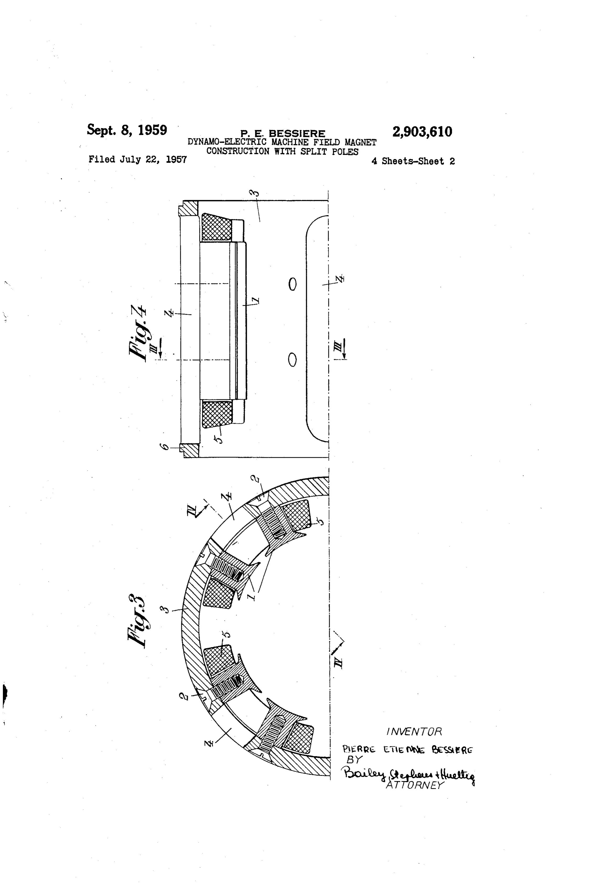
line III-III of Fig. 4 and in longitudinal section on the It prevents an undesirable armature reaction flux from line IV-IV of Fig. 3, another modification of the in 50 being closed through the cage, thus practically eliminat ductor device according to the invention.
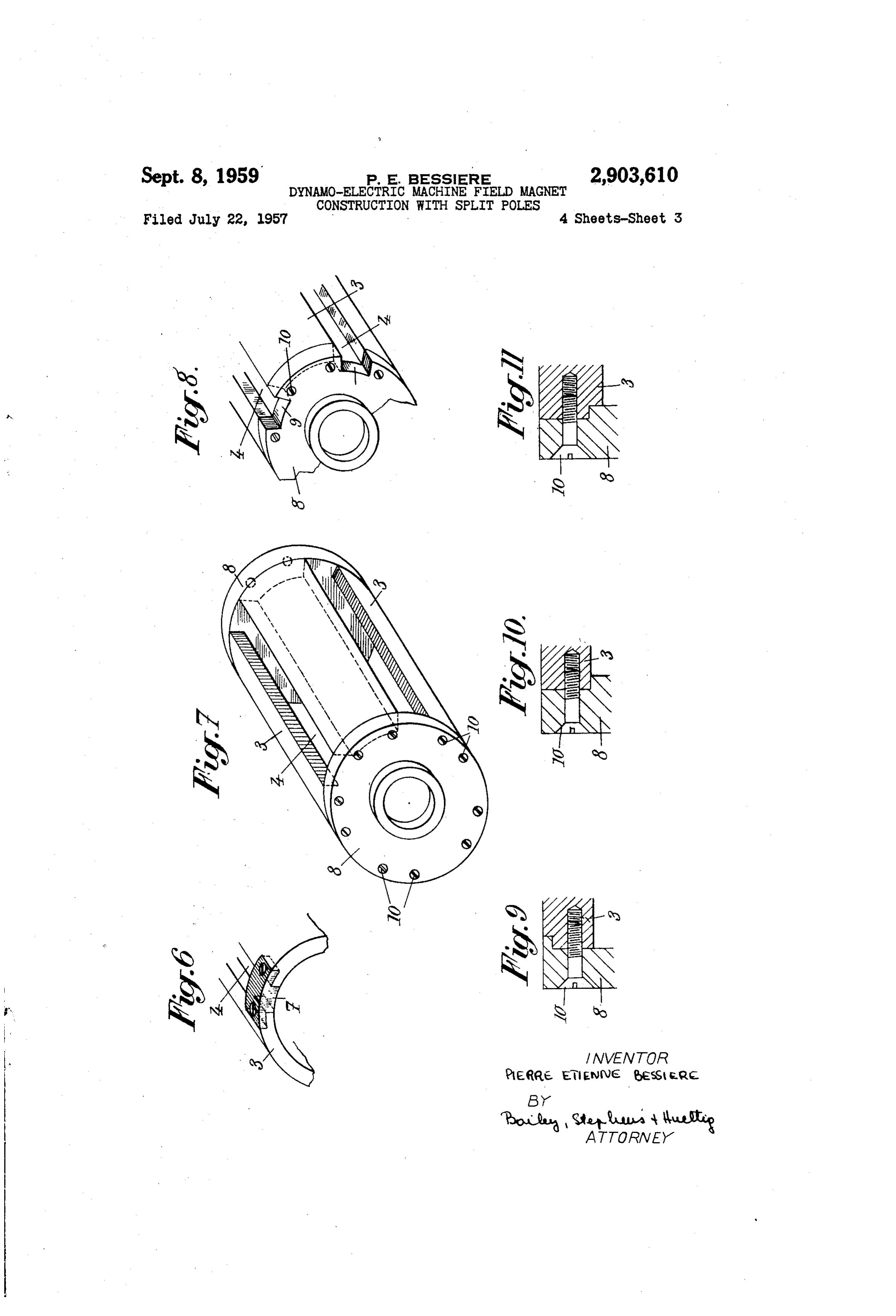
Figs. 5 to 8 are perspective views illustrating other ingItSuch flux, permits of reducing the weight of the cage.
modifications of this invention, respectively. The non magnetic material which constitutes said gaps Figs. 9 to 11 are longitudinal sections of three modi may be either gaseous (air for instance) or solid (stain fications of a detail of a cage made according to Figs. 55 less steel, aluminium, and so on . . .).
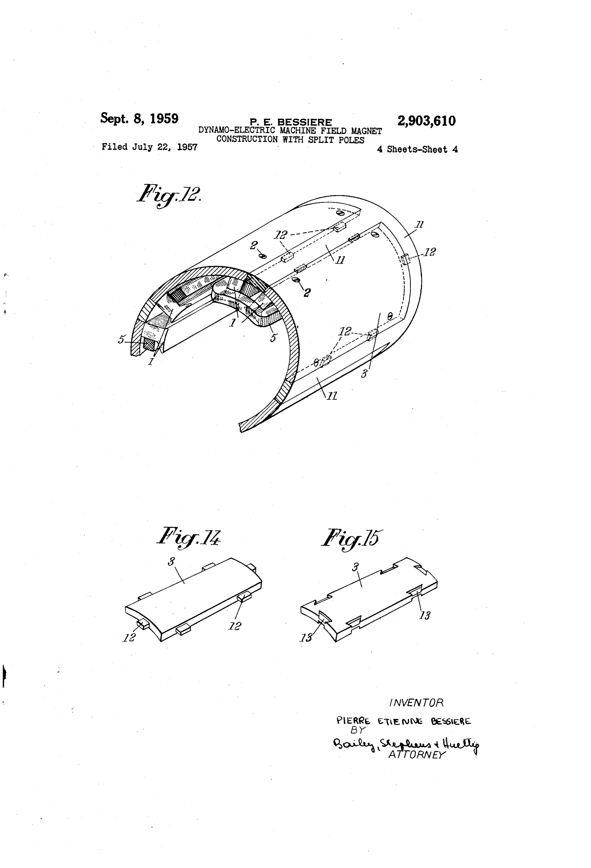
Figs. 12 and 13 show, respectively in perspective views easy.The assembly of the bars of such an inductor is very It suffices, for this purpose, to slip the coils 5 on and in longitudinal section, still another modification of the respective the invention. pairs of core elements forming the poles, Figs. 14 and 15 show two modifications of an ele 60 (mounted thereonsaidonpairs and then to fix the of core elements with the coils bars 3 of the cage by means of ment of the device of the Figs. 12 and 13.
It will be supposed in the following description that Screws 2.
In the construction of Fig. 1, the cage as a whole is the invention is applied to the construction of an in constituted by a tubular piece of a magnetic material in ductor for a dynamo or a starter having a high power for a given weight. which are provided slots 4 which form the air gaps (such It should first be reminded that, chiefly for purposes 65 slots being formed by milling or by cutting with a blow of reducing the weight and eliminating the armature pipe), the bars 3 consisting of the portions of said tubular reaction, it has already been proposed, in inductor de piece that are left between said slots 4. It will be seen vices having projecting poles and for use in electrical that the undesirable armature reaction flux which tends rotating machines, to constitute each of the poles by two to propagate in a circumferential direction in every pole core elements practically insulated from each other, from 70 can in the present case be formed only by passing through the magnetic point of view, by a non magnetic space, the “bridges' 6 of magnetic material which are left at
Page 6
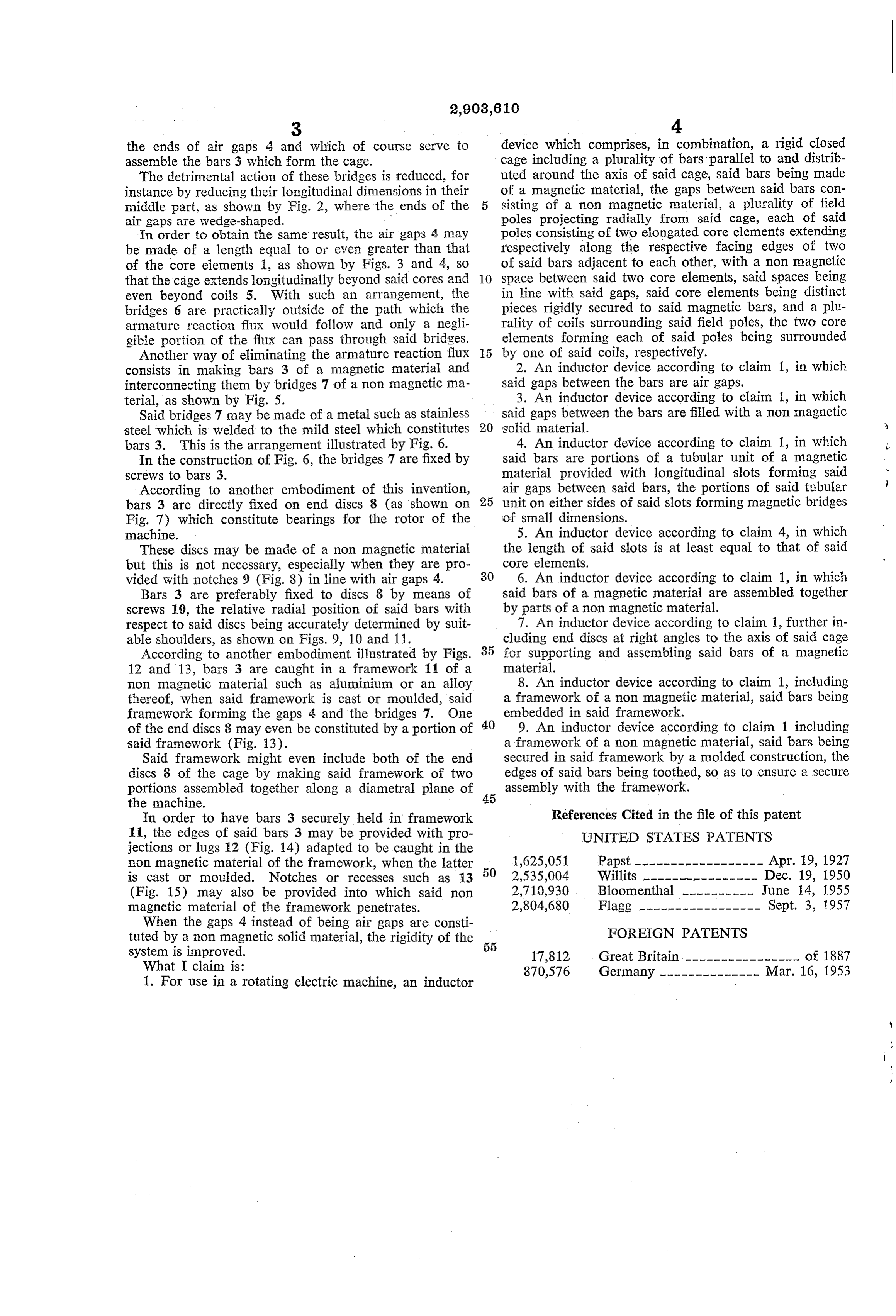
the ends of air gaps 4 and which of course serve t device which comprises, in combination, a rigid closed assemble the bars 3 which form the cage. cage including a plurality of bars parallel to and distrib The detrimental action of these bridges is reduced, for uted around the axis of said cage, said bars being made instance by reducing their longitudinal dimensions in their of a magnetic material, the gaps between said bars con middle part, as shown by Fig. 2, where the ends of the sisting of a non magnetic material, a plurality of field air gaps are wedge-shaped. poles projecting radially from said cage, each of said In order to obtain the same result, the air gaps 4 may poles consisting of two elongated core elements extending be made of a length equal to or even greater than that respectively along the respective facing edges of two of the core elements a, as shown by Figs. 3 and 4, so of said bars adjacent to each other, with a non magnetic that the cage extends longitudinally beyond said cores and 10 space between said two core elements, said spaces being even beyond coils 5. With Such an arrangement, the in line with said gaps, said core elements being distinct bridges 6 are practically outside of the path which the pieces rigidly secured to said magnetic bars, and a plu armature reaction flux would follow and only a negli rality of coils surrounding said field poles, the two core gible portion of the flux can pass through said bridges. elements forming each of said poles being surrounded Another way of eliminating the armature reaction flux by one of said coils, respectively. consists in making bars 3 of a magnetic material and 2. An inductor device according to claim 1, in which interconnecting them by bridges 7 of a non magnetic ma said gaps between the bars are air gaps. terial, as shown by Fig. 5. 3. An inductor device according to claim 1, in which Said bridges 7 may be made of a metal such as stainless said gaps between the bars are filled with a non magnetic steel which is welded to the mild steel which constitutes 20 Solid material.
bars 3. This is the arrangement illustrated by Fig. 6. 4. An inductor device according to claim 1, in which In the construction of Fig. 6, the bridges 7 are fixed by said bars are portions of a tubular unit of a magnetic screws to bars 3. material provided with longitudinal slots forming said According to another embodiment of this invention, air gaps between said bars, the portions of said tubular bars 3 are directly fixed on end discs 8 (as shown on 25 unit on either sides of said slots forming magnetic bridges Fig. 7) which constitute bearings for the rotor of the of Small dimensions.
machine. 5. An inductor device according to claim 4, in which These discs may be made of a non magnetic material the length of said slots is at least equal to that of said but this is not necessary, especially when they are pro core elements.
vided with notches 9 (Fig. 8) in line with air gaps 4. 30 6. An inductor device according to claim 1, in which Bars 3 are preferably fixed to discs 8 by means of said bars of a magnetic material are assembled together screws 10, the relative radial position of said bars with by parts of a non magnetic material. respect to said discs being accurately determined by suit 7. An inductor device according to claim 1, further in able shoulders, as shown on Figs. 9, 10 and 11. cluding end discs at right angles to the axis of said cage According to another embodiment illustrated by Figs. 35 for Supporting and assembling said bars of a magnetic 12 and 13, bars 3 are caught in a framework 11 of a material.
non magnetic material such as aluminium or an alloy 8. An inductor device according to claim 1, including thereof, when said framework is cast or moulded, said a framework of a non magnetic material, said bars being framework forming the gaps 4 and the bridges 7. One 40 embedded in said framework.
of the end discs 8 may even be constituted by a portion of 9. An inductor device according to claim 1 including said framework (Fig. 13). a framework of a non magnetic material, said bars being Said framework might even include both of the end secured in said framework by a molded construction, the discs 8 of the cage by making said framework of two edges of said bars being toothed, so as to ensure a secure portions assembled together along a diametral plane of 45 assembly with the framework.
the machine.
In order to have bars 3 securely held in framework References Cited in the file of this patent 11, the edges of said bars 3 may be provided with pro UNITED STATES PATENTS jections or lugs 12 (Fig. 14) adapted to be caught in the non magnetic material of the framework, when the latter 50 1,625,051 Papst ------------------ Apr. 19, 1927 is cast or moulded. Notches or recesses such as 13 2,535,004 Willits -------p w are arr - a - Dec. 19, 1950 (Fig. 15) may also be provided into which said non 2,710,930 Bloomenthal ---------- June 14, 1955 magnetic material of the framework penetrates. 2,804,680 Flagg ----------------- Sept. 3, 1957 When the gaps 4 instead of being air gaps are consti FOREIGN PATENTS tuted by a non magnetic solid material, the rigidity of the 55 system is improved. 17,812 Great Britain ---------------- of 1887 What I claim is: 870,576 Germany -------------- Mar. 16, 1953 1. For use in a rotating electric machine, an inductor
Provenance
- Collection
- Cited prior art
- Original PDF
- patentimages.storage.googleapis.com →
- Filed
- 1957-07-22
- Pages
- 6
- Method
- pdftotext (the PDF's own text layer) + pdftoppm 300dpi page scans
- Source
- Google Patents bibliographic record
- Granted
- 1959-09-08
- Inventors
- Bessiere Pierre Etienne; Labinal SA
- Transcribed from
- patentimages.storage.googleapis.com →