patent · US3468548
Rotating shaft seal
23 September 1969
Page 1
Drawing sheet — no readable text.
Page 2
United States Patent Office Patented Sept. 23, 1969
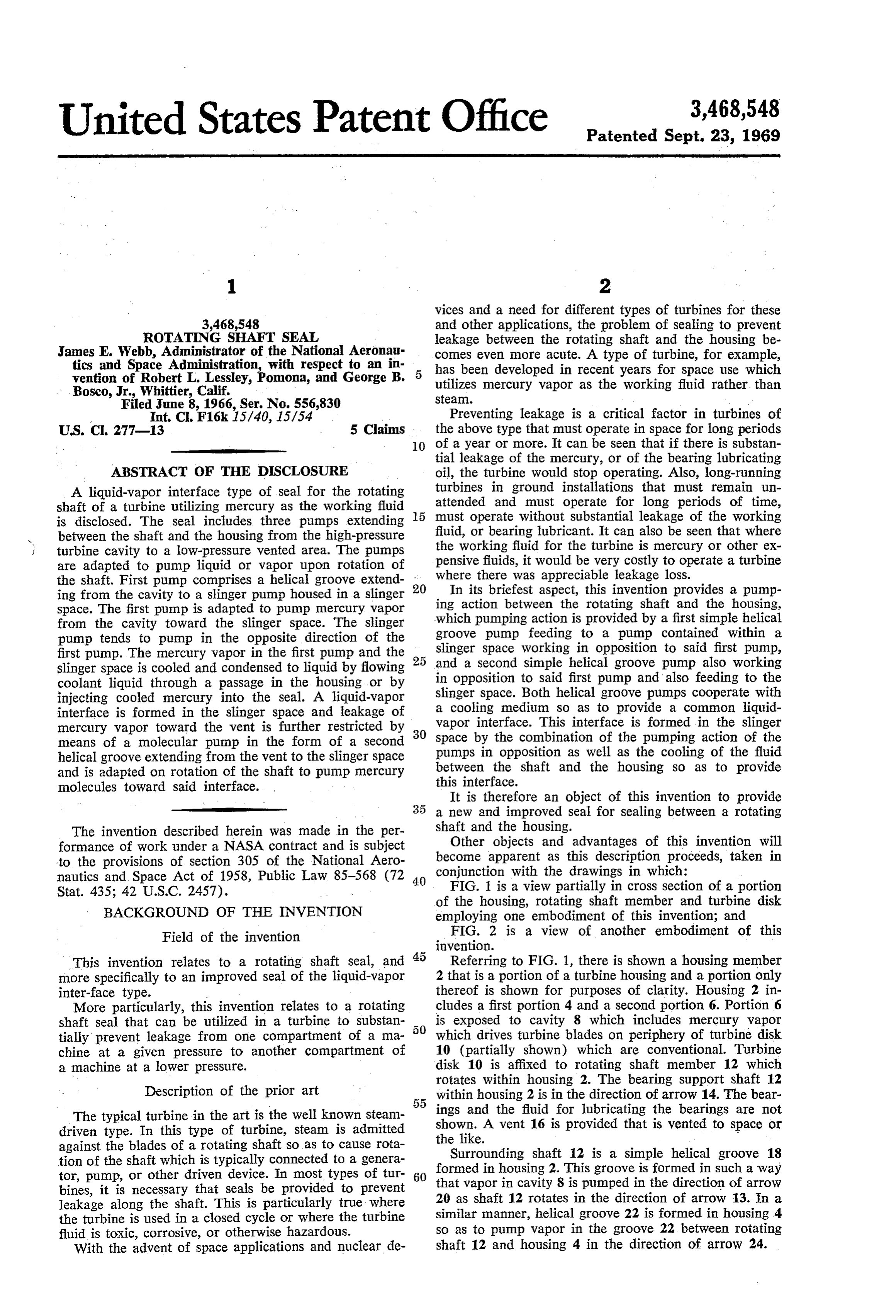
vices and a need for different types of turbines for these 3,468,548 and other applications, the problem of sealing to prevent ROTATING SHAFT SEAL leakage between the rotating shaft and the housing be James E. Webb, Administrator of the National Aeronau comes even more acute. A type of turbine, for example, tics and Space Administration, with respect to an in has been developed in recent years for space use which vention of Robert L. Lessley, Pomona, and George B. utilizes mercury vapor as the working fluid rather, than Bosco, Jr., Whittier, Calif. Steal.
Filed June 8, 1966, Ser. No. 556,830 Preventing leakage is a critical factor in turbines of
U.S. C. 277-13 5 Claims . the above type that must operate in space for long periods 0 of a year or more. It can be seen that if there is substan tial leakage of the mercury, or of the bearing lubricating
ABSTRACT OF THE DISCLOSURE oil, the turbine would stop operating. Also, long-running A liquid-vapor interface type of seal for the rotating turbines in ground installations that must remain un shaft of a turbine utilizing mercury as the working fluid 5 attended and must operate for long periods of time, is disclosed. The seal includes three pumps extending must operate without substantial leakage of the working between the shaft and the housing from the high-pressure fluid, or bearing lubricant. It can also be seen that where turbine cavity to a low-pressure vented area. The pumps the working fluid for the turbine is mercury or other ex are adapted to pump liquid or vapor upon rotation of pensive fluids, it would be very costly to operate a turbine the shaft. First pump comprises a helical groove extend 20 where there was appreciable leakage loss. ing from the cavity to a slinger pump housed in a slinger In its briefest aspect, this invention provides a pump space. The first pump is adapted to pump mercury vapor ing action between the rotating shaft and the housing, from the cavity toward the slinger space. The slinger which pumping action is provided by a first simple helical pump tends to pump in the opposite direction of the groove pump feeding to a pump contained within a slinger space Working in opposition to said first pump, first pump. The mercury vapor in the first pump and the 25 and slinger space is cooled and condensed to liquid by flowing a second simple helical groove pump also working in opposition to said first pump and also feeding to the coolant liquid through a passage in the housing or by slinger injecting cooled mercury into the seal. A liquid-vapor space. Both helical groove pumps cooperate with interface is formed in the slinger space and leakage of a cooling medium so as to provide a common liquid mercury vapor toward the vent is further restricted by 30 vapor interface. This interface is formed in the slinger means of a molecular pump in the form of a second space by the combination of the pumping action of the helical groove extending from the vent to the slinger space pumps in opposition as well as the cooling of the fluid and is adapted on rotation of the shaft to pump mercury between the shaft and the housing so as to provide molecules toward said interface. this interface.
It is therefore an object of this invention to provide a new and improved seal for sealing between a rotating
The invention described herein was made in the per shaft and the housing.
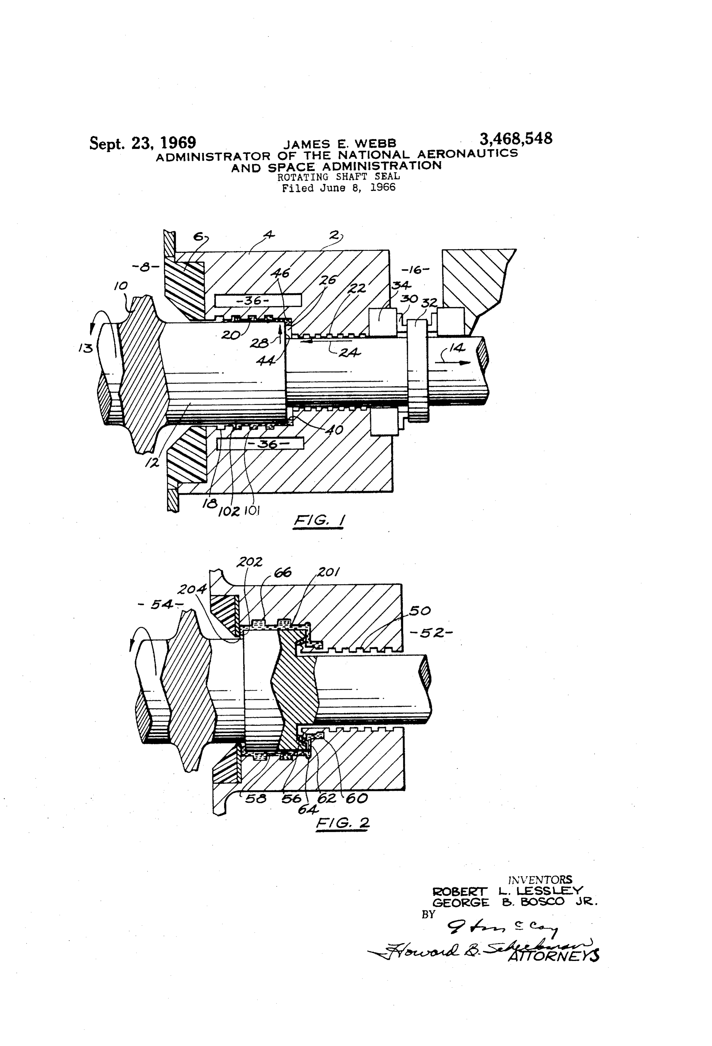
formance of work under a NASA contract and is subject Other objects and advantages of this invention will to the provisions of section 305 of the National Aero become apparent as this description proceeds, taken in nautics and Space Act of 1958, Public Law 85-568 (72 40 conjunction with the drawings in which: FIG. 1 is a view partially in cross section of a portion
Stat. 435; 42 U.S.C. 2457). of the housing, rotating shaft member and turbine disk BACKGROUND OF THE INVENTION employing one embodiment of this invention; and Field of the invention FIG. 2 is a view of another embodiment of this invention.
This invention relates to a rotating shaft seal, and 45 Referring to FIG. 1, there is shown a housing member more specifically to an improved seal of the liquid-vapor 2 that is a portion of a turbine housing and a portion only inter-face type. thereof is shown for purposes of clarity. Housing 2 in More particularly, this invention relates to a rotating cludes a first portion 4 and a second portion 6. Portion 6 shaft seal that can be utilized in a turbine to substan is exposed to cavity 8 which includes mercury vapor tially prevent leakage from one compartment of a ma which drives turbine blades on periphery of turbine disk chine at a given pressure to another compartment of 10 (partially shown) which are conventional. Turbine a machine at a lower pressure. disk 10 is affixed to rotating shaft member 12 which rotates within housing 2. The bearing support shaft 12
Description of the prior art within housing 2 is in the direction of arrow 14. The bear The typical turbine in the art is the well known steam ings and the fluid for lubricating the bearings are not driven type. In this type of turbine, steam is admitted theshown. A vent 16 is provided that is vented to space or against the blades of a rotating shaft so as to cause rota like.
tion of the shaft which is typically connected to a genera Surrounding shaft 12 is a simple helical groove 18 formed in housing 2. This groove is formed in such a way tor, pump, or other driven device. In most types of tur 60 that bines, it is necessary that seals be provided to prevent 20 asvapor in cavity 8 is pumped in the direction of arrow shaft 12 rotates in the direction of arrow 13. In a leakage along the shaft. This is particularly true where the turbine is used in a closed cycle or where the turbine similar manner, helical groove 22 is formed in housing 4 fluid is toxic, corrosive, or otherwise hazardous. so as to pump vapor in the groove 22 between rotating With the advent of space applications and nuclear de shaft 12 and housing 4 in the direction of arrow 24.
Page 3
s 4.
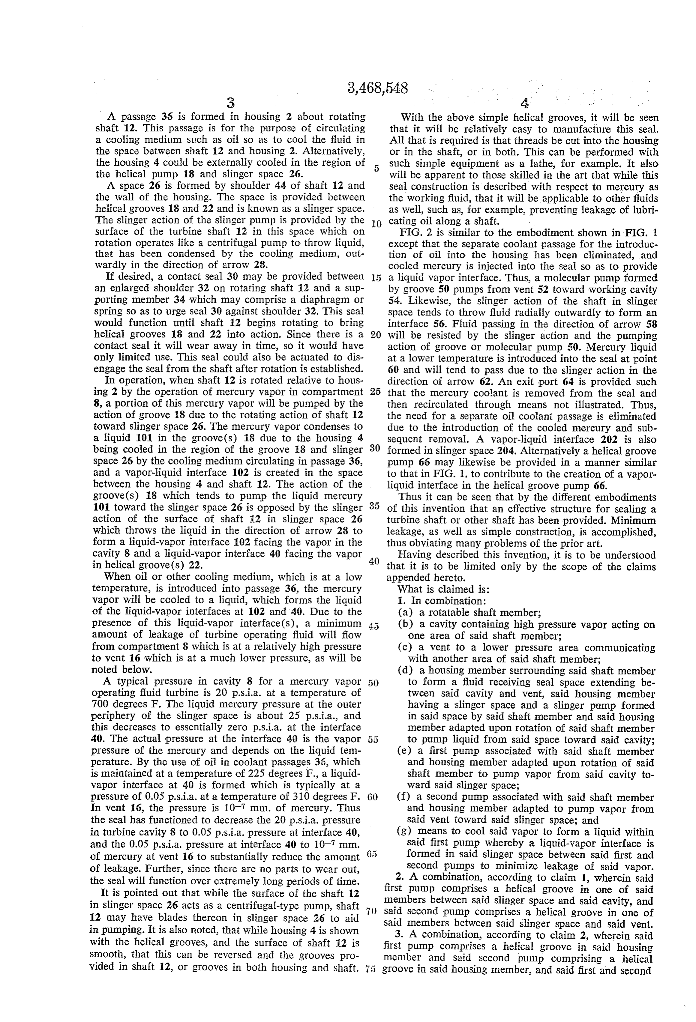
A passage 36 is formed in housing 2 about rotating With the above simple helical grooves, it will be seen shaft 12. This passage is for the purpose of circulating that it will be relatively easy to manufacture this seal. a cooling medium such as oil so as to cool the fluid in All that is required is that threads be cut into the housing the space between shaft 12 and housing 2. Alternatively, or in the shaft, or in both. This can be performed with the housing 4 could be externally cooled in the region of such simple equipment as a lathe, for example. It also the helical pump 18 and slinger space 26. will be apparent to those skilled in the art that while this A space 26 is formed by shoulder 44 of shaft 12 and seal construction is described with respect to mercury as the wall of the housing. The space is provided between the working fluid, that it will be applicable to other fluids helical grooves 18 and 22 and is known as a slinger space. as well, such as, for example, preventing leakage of lubri The slinger action of the slinger pump is provided by the 0 cating oil along a shaft.
surface of the turbine shaft 12 in this space which on FIG. 2 is similar to the embodiment shown in FIG. 1 rotation operates like a centrifugal pump to throw liquid, except that the separate coolant passage for the introduc that has been condensed by the cooling medium, out tion of oil into the housing has been eliminated, and wardly in the direction of arrow 28. cooled mercury is injected into the seal so as to provide If desired, a contact seal 30 may be provided between 5 a liquid vapor interface. Thus, a molecular pump formed an enlarged shoulder 32 on rotating shaft 12 and a Sup by groove 50 pumps from vent 52 toward working cavity porting member 34 which may comprise a diaphragm or 54. Likewise, the slinger action of the shaft in slinger spring so as to urge seal 30 against shoulder 32. This seal space tends to throw fluid radially outwardly to form an would function until shaft 12 begins rotating to bring interface 56. Fluid passing in the direction of arrow 58 helical grooves 18 and 22 into action. Since there is a 20 will be resisted by the slinger action and the pumping contact seal it will wear away in time, so it would have action of groove or molecular pump 50. Mercury liquid only limited use. This seal could also be actuated to dis at a lower temperature is introduced into the seal at point engage the seal from the shaft after rotation is established. 60 and will tend to pass due to the slinger action in the In operation, when shaft 12 is rotated relative to hous direction of arrow 62. An exit port 64 is provided such ing 2 by the operation of mercury vapor in compartment 25 that the mercury coolant is removed from the seal and 8, a portion of this mercury vapor will be pumped by the then recirculated through means not illustrated. Thus, action of groove 18 due to the rotating action of shaft 12 the need for a separate oil coolant passage is eliminated toward slinger space 25. The mercury vapor condenses to due to the introduction of the cooled mercury and Sub a liquid 101 in the groove(s) 18 due to the housing 4 sequent removal. A vapor-liquid interface 202 is also being cooled in the region of the groove 18 and slinger 30 formed in slinger space 204. Alternatively a helical groove space 26 by the cooling medium circulating in passage 36, pump 66 may likewise be provided in a manner similar and a vapor-liquid interface 102 is created in the space to that in FIG. 1, to contribute to the creation of a vapor between the housing 4 and shaft 12. The action of the liquid interface in the helical groove pump 66. groove(s) 18 which tends to pump the liquid mercury Thus it can be seen that by the different embodiments 101 toward the slinger space 26 is opposed by the slinger of this invention that an effective structure for sealing a action of the surface of shaft 12 in slinger space 26 turbine shaft or other shaft has been provided. Minimum which throws the liquid in the direction of arrow 28 to leakage, as well as simple construction, is accomplished, form a liquid-vapor interface 102 facing the vapor in the thus obviating many problems of the prior art. cavity 8 and a liquid-vapor interface 40 facing the vapor 40 Having described this invention, it is to be understood in helical groove(s) 22. that it is to be limited only by the scope of the claims When oil or other cooling medium, which is at a low appended hereto.
temperature, is introduced into passage 36, the mercury What is claimed is:
vapor will be cooled to a liquid, which forms the liquid 1. In combination:
of the liquid-vapor interfaces at 102 and 49. Due to the (a) a rotatable shaft member; presence of this liquid-vapor interface(s), a minimum (b) a cavity containing high pressure vapor acting on amount of leakage of turbine operating fluid will flow one area of said shaft member; from compartment 8 which is at a relatively high pressure (c) a vent to a lower pressure area communicating to vent 16 which is at a much lower pressure, as will be with another area of said shaft member; noted below. (d) a housing member surrounding said shaft member A typical pressure in cavity 8 for a mercury vapor to form a fluid receiving seal space extending be operating fluid turbine is 20 p.s.i.a. at a temperature of tween said cavity and vent, said housing member 700 degrees F. The liquid mercury pressure at the outer having a slinger space and a slinger pump formed periphery of the slinger space is about 25 p.s.i.a., and in said space by said shaft member and said housing this decreases to essentially zero p.S.i.a. at the interface member adapted upon rotation of said shaft member 40. The actual pressure at the interface 40 is the vapor 5 5 to pump liquid from said space toward said cavity; pressure of the mercury and depends on the liquid tem (e) a first pump associated with said shaft member perature. By the use of oil in coolant passages 36, which and housing member adapted upon rotation of said is maintained at a temperature of 225 degrees F., a liquid shaft member to pump vapor from said cavity to vapor interface at 40 is formed which is typically at a ward said slinger space;
pressure of 0.05 p.s.i.a. at a temperature of 310 degrees F. 60 (f) a Second pump associated with said shaft member In vent 16, the pressure is 10 mm. of mercury. Thus and housing member adapted to pump vapor from the seal has functioned to decrease the 20 p.s.i.a. pressure said vent toward said slinger space; and in turbine cavity 8 to 0.05 p.s.i.a. pressure at interface 40, (g) means to cool said vapor to form a liquid within and the 0.05 p.s.i.a. pressure at interface 40 to 10 mm. Said first pump whereby a liquid-vapor interface is of mercury at vent 6 to substantially reduce the amount formed in said slinger space between said first and of leakage. Further, since there are no parts to Wear out, Second pumps to minimize leakage of said vapor. the seal will function over extremely long periods of time. 2. A combination, according to claim 1, wherein said It is pointed out that while the surface of the shaft 12 first pump comprises a helical groove in one of said members between said slinger space and said cavity, and in slinger space 26 acts as a centrifugal-type pump, shaft 70 Said 12 may have blades thereon in slinger space 26 to aid Second pump comprises a helical groove in one of in pumping. It is also noted, that while housing 4 is shown Said members between said slinger space and said vent. with the helical grooves, and the surface of shaft 12 is 3. A combination, according to claim 2, wherein said first pump comprises a helical groove in said housing smooth, that this can be reversed and the grooves pro member and said second pump comprising a helical vided in shaft 12, or grooves in both housing and shaft. 75 groove in said housing member, and said first and second
Page 4
pump grooves extend in opposite directions away from References Cited said slinger space. UNITED STATES PATENTS 4. A combination, according to claim 1, wherein said 2,330,730 9/1943 Mosshart ------------ 277-16 means to cool said vapor comprises a passageway formed 3,076,656 2/1963 Hofmann -------- 277-134 X in said housing about said shaft member separate from 3,131,940 5/1964 Ertaud ---------- 277-134 X said seal space for circulating a cooling medium to cool 3,150,822 9/1964 Dreyfus et al. ----- 277-134 X the vapor in said first pump. 3,161,413 12/1964 Audemar --------- 277-134 X 5. A combination according to claim 1, wherein said 3,355,179 11/1967 McGrew ----------- 277-134 vapor is mercury vapor and said means to cool said 945,900 1/1910 Ahlquist ------------ 277-13 vapor comprises cooled mercury liquid at a lower tem O perature than the mercury liquid within said first pump, SAMUEL ROTHBERG, Primary Examiner said housing member including means to introduce said cooled mercury to said vapor-liquid interface, and further U.S. C. X.R. including means to remove said cooled mercury from said 277-67, 134
Seal space. 5
Provenance
- Collection
- Cited prior art
- Original PDF
- patentimages.storage.googleapis.com →
- Filed
- 1966-06-08
- Pages
- 4
- Method
- pdftotext (the PDF's own text layer) + pdftoppm 300dpi page scans
- Source
- Google Patents bibliographic record
- Granted
- 1969-09-23
- Inventors
- Robert L Lessley; George B Bosco Jr
- Transcribed from
- patentimages.storage.googleapis.com →