patent · US5777952
Thin bias magnet unit for magneto-optical recording device
7 July 1998
Page 1 — bibliographic record
United States Patent (19) 11 Patent Number: 5,777,952 Nishimura et al. 45 Date of Patent: Jul. 7, 1998 (54) THIN BLAS MAGNET UNIT FOR MAGNETO 5,587,973 12/1996 Kanazawa et al. ....................... 369/13
OPTICAL RECORDING DEVICE
FOREIGN PATENT DOCUMENTS
(75) Inventors: Hajime Nishimura, Chigasaki; Atsushi 2-126402 5/990 Japan. Ichikawa, Odawara; Akio Yabe, 5-2792 fgg3 Japan.
Fujisawa; Yuji Yokoyama, Odawara, all 5-307785 11/1993 Japan.
of Japan 5290433 1/1993 Japan.
73) Assignees: Hitahi, Ltd., Tokyo; Hitachi Primary Examiner Tan Dinh Computer Peripherals Co., Ltd., Attorney; Agent, or Firm-Fay, Sharpe. Beall, Fagan, Kanagawa-ken, both of Japan Minnich & McKee (21) Appl. No.: 678,267 57 ABSTRACT 22 Filed: Jul. 11, 1996 A bias magnet unit has a permanent magnet that applies a 30 Foreign Application Priority Data bias magnetic field to an optical spot on a magneto-optical disk. A driving coil rotates the magnet in order to change a
Jul. 12, 1995 JP Japan .................................... 7-176263 polarity of the bias magnetic field. A sensor detects the intensity and polarity of the bias magnetic field to confirm (51) Int. Cl. .................... G11B 11/00 the rotational position of the magnet after it has been rotated. 52 U.S. Cl. .......................... 369/13; 369/77.2: 369/75.2: A linkage structure that is connected between a magnet 360/114 holder of the magnet unit and the housing has arms that drive 58 Field of Search ........................... 369/13, 75.2. 75.1, the magnet unit between two positions, one in which the 369/77.2, 77.1, 78.79; 360/114,59 magneto-optical disk cartridge can be inserted into the device and another in which the disk is loaded onto the (56) References Cited spindle motor for recording?playback. Overall, the compo
relatively thin device structure having low power consump 5202,861 4/1993 Yoshida ..................................... 369/13 tion.
5,345,431 9/1994 Olivar et al. ....... ... 369/13 5.537,370 7/1996 Shigematsu et al. ..................... 36.9/13 15 Claims, 7 Drawing Sheets
Page 2
Drawing sheet — no readable text.
Page 3
Drawing sheet — no readable text.
Page 4
Drawing sheet — no readable text.
Page 5
ROTATIONAL TOROUE
OF THE BIAS MAGNET
INTENSITY OF THE
MAGNET FELDAPPLIED
VERTICALLY TO THE
OPTICAL DISC
OUTPUT OF THE
MAGNETIC SENSOR
ELECTRIC CURRENT
THROUGH THE COL
DURING CLOCKWISE
ROTATION
ELECTRIC CURRENT
THROUGH THE COIL
DURING
COUNTERCLOCKWISE
ROTATION
RANGE OF THE ROTATION OF THE MAGNET 61
ANGLE BETWEEN THE OPTICAL DISCAND THE BOUNDARY PLANE 81 THAT
EXISTS BETWEEN THE SANDN POLES OF THE BIAS MAGNET
FIG. 5
Page 6
Drawing sheet — no readable text.
Page 7
Drawing sheet — no readable text.
Page 8
Drawing sheet — no readable text.
Page 9
THIN BAS MAGNET UNIT FOR MAGNETO In Japanese Laid Open Patent Publication Hei 6-176424, OPTICAL RECORDNG DEVICE the bias magnet and the optical head are stored in a moving head. The moving head varies its location in a radial
FIELD OF THE INVENTION direction of the optical disk. The optical spot and the bias This invention is related to a magneto-optical disk device. magnetic field are applied from the same side of the disk
surface in order to minimize the thickness of the device. In in which an optical cartridge can be loaded and unloaded. such a structure, there are problems that the moving head and especially to a magneto-optical disk which is thin and becomes relatively heavy and it takes a longtime for access. operates with low power consumption.
Whether or not a permanent magnet or an electromagnet 10 is used, the intensity of the magnetic field becomes weaker
BACKGROUND OF THE INVENTION
in accordance with the increase in distance of the bias
A magneto-optical disk device has generally a spindle magnet from the surface of the disk. Accordingly, it is motor that rotates an optical disk at a predetermined speed, necessary to arrange the bias magnet as close as possible to an optical head and a signal detecting optical system that the optical disk during recording or playing back of the data. forms an optical spot at a predetermined recording position 15 For attaining this objective, structure is used to return the on the optical disk for recording and play back of data on the bias magnet to the upper area or to the side face of the optical disk. A circuit is provided for signal processing and cartridge holder during the entry (loading) or exit controlling the device and a loading mechanism receives an (unloading) of the cartridge.
inserted disk cartridge and transfers the optical disk therein In Japanese Laid Open Patent Publication Hei 5-307785. into a position in which data is recorded or played back. The 20 a bias magnet is disclosed that is moved in advance inside device also includes a bias magnet unit having a magnet that to a position wherein the optical cartridge is transferred by applies a magnetic field to the optical spot, a magnet a loading mechanism and wherein an optical disk is set into supporter, and a magnetic sensor that detects a polarity of the position with respect to the optical head. At the same time bias magnetic field. with the setting of the optical disk onto the spindle motor, The spindle motor and the optical head are located well 25 the bias magnet advances along the optical disk to the inside the device so that it is difficult for an operator to set position where it faces the optical head and a bias magnetic the optical disk cartridge directly onto the spindle motor field is applied. There are problems with this design, how because of the device structure. Therefore, in the magneto ever. Since the bias magnet is moved or retreated inside the optical disk device, a cartridge holder in the loading mecha setting position of the optical disk cartridge, it is necessary nism is loaded inside horizontally and then descends verti to reserve a space for the bias magnet in this position and to cally. This efficiently positions the cartridge in order to provide a mechanism to set the magnet. It also takes more position a center of the optical disk onto the spindle motor. time to transport the bias magnet back and forth. In the magneto-optical disk device, the data is recorded or In Japanese Laid Open Patent Publication Hei 2-126402, erased by focusing the optical spot and by applying the bias 35 a bias magnet is arranged between a device cover that is magnetic field vertically to the surface of the disk at the positioned at the upper part of an optical disk cartridge, in recording spot. The polarities of the applied magnetic field the inserting position, and a cartridge holder so that the bias are reversed during recording or erasing. magnet does not interfere with the insertion of the optical The bias magnetic structure in the prior art uses either disk cartridge. The bias magnetic field application structure permanent magnet or an electromagnet. Japanese Laid Open 40 brings the bias magnet closer to the optical disk when the Patent Publication Hei 5-2792, discloses using an electro cartridge is inserted and the optical disk is set to a spindle magnet as the bias magnet and the polarity of the applied motor. By the vertical movement of the loading mechanism magnetic field is reversed by switching the directions of that transfers the optical disk cartridge, a leaf spring attached electric current flowing through a coil of the electromagnet. to the side face of the bias magnet is moved vertically and However, it is inconvenient to use an electromagnet as the 45 the bias magnet is brought closer to the optical disk with a bias magnetic field because the coil needs to at least 8 mm leverage mechanism. However, the thickness of the bias in thickness and this makes it difficult to design a thin magnet and the above up-and-down structure is approxi device. mately 10 mm. Therefore in the case of a 5 inch half height On the other hand, Japanese Laid Open Patent Publication tridge size magneto-optical disk device, a space between the car Hei 6-176424, discloses using a permanent magnet as the 50 upon would holder and the components that are positioned there bias magnet and a permanent magnet driving coil surrounds arrange a circuit be only around 3 mm. There may be a need to a cylindrical permanent magnet that is rotated by an elec prepare holes therein, board above the cartridge holder and to tromagnetic interaction between a current through the driv ing the circuit board. which results in a difficulty of design ing coil and a magnetic field generated by the permanent magnet. Consequently the polarity of the magnetic field 55 SUMMARY OF THE INVENTION applied by the permanent magnet is reversed. The driving The present invention is intended to provide a thin bias coil of this type is arranged vertically to the radial direction magnet structure that can apply a bias magnetic field in a of the optical disk in order to generate a large driving torque magneto optical disk device and that uses a thin rotating at start and stop for rotating the bias magnet and to get a permanent magnet with a thickness of approximately 2 mm quick change of the bias magnetic polarities. for applying the bias magnetic field. Further it is intended to For the above types of devices, a magnetic sensor detects provide a thin linkage and movement structure that positions a rotational angle of the bias magnet. The output signal at a the bias magnet vertically between two positions, one in predetermined rotational angle triggers a change of the which the magneto-optical disk cartridge can be inserted current of the driving coil, which stops the rotation of the into the device and another in which the disk is loaded onto bias magnet. The magnetic sensor is arranged in the direc 65 the spindle motor for recording/playback and the magnet so tion of thickness of the bias magnet in order to detect the that the magnet is positioned close to the optical disk with angle precisely. excellent height accuracy.
Page 10
To attain the objects of the invention, the following can be decelerated by changing the rotation driving current engineering problems were considered. or switching directions of the current during the rotating When a boundary plane between the S and N poles of a movement of the magnet.
rotating bias magnet is positioned in line with the main plane The second object was solved as follows. Concerning the of a driving coil, the torque to rotate the magnet goes to zero. structure that moves the bias magnet up and down, the Consequently the driving coil can not make the magnet stop magneto-optical disk device has a side cover that faces the or start its rotating. (Here, because the device is designed to side of the cartridge holder and that is fixed to the device be thin, the magnet is shaped like a plate and it is magnetized base, loading mechanism moves the cartridge holder that vertically with respect to the plate's surface.) Although holds the optical disk cartridge vertically or horizontally arranging the driving coil and the bias magnet simply in O and-vertically, to transfers the cartridge vertically or parallel to the optical disk makes the magneto-optical disk horizontally-and-vertically, device thinner than prior devices, the rotating torque applied In the structure that moves the bias magnet up and down, to the magnet for changing its orientation and consequently there are arms, each of which has a central linear portion, the polarity of the applied magnetic field reaches a dead and both ends of which are L shaped. The central linear point in which the torque is zero and the bias magnet cannot 15 portion is pivoted by bearings mounted on an upper surface be rotated. of the cartridge holder, and one L shaped tip of the arm is In consideration of a mechanical part which brings the engaged with a hole arranged on a side surface of the bias bias magnet closer to the optical disk during recording or magnet and the other L shaped tip is engaged in a hole on playing back of the data, in the prior art, the distance in the side cover. At least one of the hole on the side of the bias which the bias magnet is moved to the optical disk is 20 magnet or the hole of the side cover is formed to be a slot required to be similar to the height between a cartridge or a long hole. The L shaped portions are engaged with the holder and the components placed thereupon. In the present slots or long holes. The angle between the L shaped portion invention, the these considerations were as follows. and the upper surface of the cartridge holder is offset form During loading or unloading of the optical disk cartridge. 25 being 90 degrees at the start, operation and end of the a thickness of the structure that moves the bias magnet up loading or unloading (if the angle is 90 degrees, i.e. the L and down should be equal to or less than a thickness of the shaped portion is perpendicular to the surface of the car bias magnet and the bias magnet should be stopped at a tridge holder, the cartridge holder cannot move or descend). position that does not interfere with the loading or unloading The slider bearing surfaces secure a smooth rotation of the of the cartridge. arms and a stable up-and-down movement of the bias Further, during recording or playing back of the data, the magnet.
bias magnet should be placed closer to the optical disk and The slots or holes on the upper surface of the cartridge a certain space should be kept between the components holder and the side surface of the bias magnet are arranged above the cartridge holder and the bias magnet. so that distances between the holes of the cartridge holder The first object of the present invention was to arrange 35 are longer than distances between the holes of the bias each element of the bias magnet unit using the rotational magnet. A stopper arm that links the holes of the cartridge permanent magnet, such as, the thin permanent magnet, the holder with the holes of the bias magnet can stop descending driving coil and a magnetic sensor, above the cartridge of the bias magnet with high precision. Further, stopper holder within a space similar to the thickness of the perma portions are mounted on the cartridge holder or the bias nent magnet so that the driving coil could rotate the bias magnet so that ascending of the bias magnet can be stopped magnet securely and stably. at a position wherein the lower surface of the bias magnet The second object of the invention was to keep a thickness and or the upper surface of the cartridge holder are nearly equal level.
of the structure that moves the bias magnet up and down, which has a function to move the bias magnet closer to the Using the above the above structure, the rotational angle optical disk with high precision, similar to the thickness of 45 of the magnetis limited by the stopper portions. As the main the bias magnet during loading or unloading of the disk plane of the magnet driving coil does not come to be in cartridge. parallel with the boundary plane between the S and N poles The first object was solved by attaching cylindrical shaft of the bias magnet, the rotating torque for the bias magnet stubs to each end of a bias magnet having a thickness of is not decreased to zero. Therefore the structure prevents the about 2 mm, supporting the shafts with a magnet holder that 50 bias magnet from stopping its rotation between the opposite has slider bearing surfaces for supporting the shafts in polarity magnetic field applying positions. rotation, providing a space at its center for the magnet to Before the magnet is stopped in rotation by the stopper rotate, and arranging a magnet rotation driving coil and a portion, the current through the driving coil is changed for magnetic sensor that detects a rotational angle of the magnet a deceleration of the rotational speed. Thus, a shock of the and a stopped position of the magnet's rotation, within a 55 collision is decreased and a damage of the magnet and the region that is defined between a plane parallel to the optical stopper portion is suppressed. Consequently the magnet and disk which includes a point of the magnet closest to the disk stopper can have a longer life.
and another plane parallel to the optical disk which includes An intensity of the bias magnetic field applied to the a point of the magnetfarthest from the disk. By attaining this optical disk can be made constant by holding a magnet objective, the thickness is minimized. Also, the limit of position where the bias magnet is stopped in rotation. The rotation of the magnet by a stopper is provided in order to holding is attained by flowing an electric current through the prevent the magnet from reaching a position that is a dead driving coil in the direction that makes the bias magnet spot in the rotating torque, i.e. a point at which the torque continuously engage the stopper portion. An output of the becomes zero. magnetic sensor that is arranged near the side face of the bias A life of the magnet holder may be prolonged by allevi 65 magnet can be monitored to detect the polarity and intensity ating any shock associated with the collision of the magnet of the bias magnetic field applied to the optical disk to with the stopper by decelerating the rotation. The rotation confirm proper positioning of the magnet after rotating it.
Page 11
S 6
The structure that moves the bias magnet up and down is "horizontal', 'vertical", "ascend", and "descend” and other provided with a pair of L shaped portions. By a rotational words expressing relative positioning of the components of movement in combination with a horizontal or a vertical the disk device are to be given their normal meaning. that is movement of the L shaped arms of which the tips are a meaning consistent with the device being positioned engaged with the slots or long holes on the side cover, the horizontally on a work surface, for example. Of course, the bias magnet, with which the other tips of the L shaped arms device is intended to be operational in any orientation are engaged, is transferred vertically, During the loading or consistent with the use of the device in a computer, for unloading of the optical disk cartridge, the bias magnet is example. Further, since it is intended that an operator will retreated into the space between the cartridge holder and the insert an optical disk cartridge into the disk device, the side components that are positioned on the cartridge holder. O facing the operator is disclosed as the outer side, meaning During recording or playing back of the data, the bias the external side and the other internal side is disclosed as magnet is brought closer to the optical disk. Since the end being the "inner side".
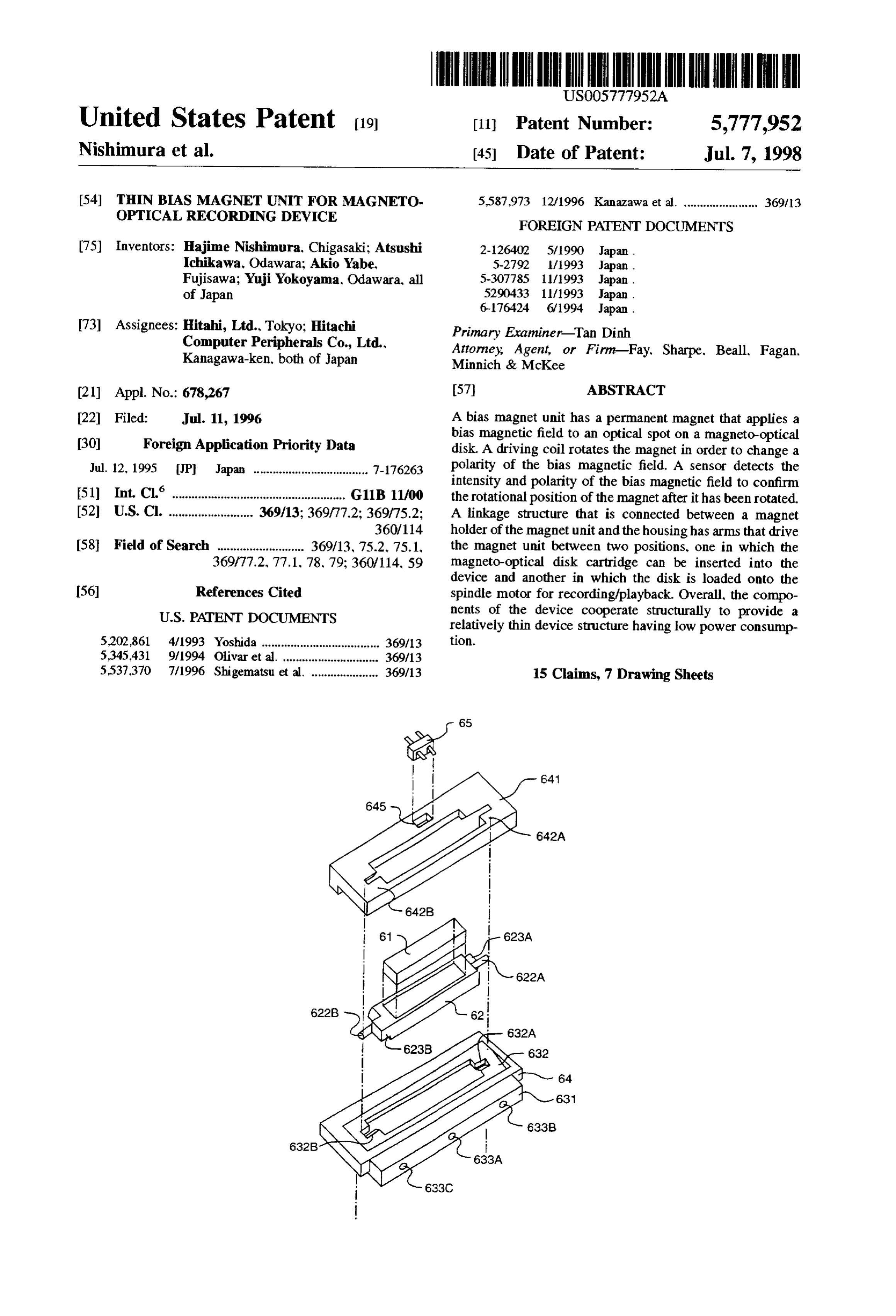
portions of the arms of structure that moves the bias magnet FIG. 1 is a perspective view of the magneto-optical disk up and down, which are engaged with the slots or long holes device of the present invention, according to a preferred arranged on the side cover, and the upper surface of the 5 embodiment. The magneto-optical disk device includes a cartridge holder are always kept at an acute angle, the tips unit mechanism or housing 3 on which a spindle motor and of the L shaped portions do not touch the side surfaces of the an optical head (not shown) are mounted. On a fixed portion holes at a right angle. That is to say, the tips are not locked 4 of the disk device, a semiconductor laser is intended to be and do not stop ascending or descending the cartridge mounted, along with the optical components normally asso holder. 20 ciated with the laser, as well as a signal detection system and Also, preferably the vertical transfer distance of the bias so forth (not shown). The fixed portion 4 also includes a magnet is limited by stopper arms that engage the slots in the circuit portion 5that provides the signal processing function cartridge holder and the bias magnet. Further, the stopper necessary for the operation of the device, such as the signal arms preferably have L shaped arms at their ends. The bias detection processing circuit, the signal processing circuit magnet does not touch the optical disk surface as a result of 25 and the drive controller for the mechanisms of the disk the stopper arms. Also, since the ascent of the bias magnet device, etc.
is limited by the stoppers mounted on the cartridge holder or A loading mechanism 2 is used for guiding the insertion the bias magnet, the bias magnet does not touch the com of the magneto-optical disk cartridge 1 into the disk device. ponents that are positioned above the cartridge holder. A bias magnet portion 6 applies a bias magnetic field to the
BRIEF DESCRIPTION OF THE DRAWINGS
optical disk 12 located within the cartridge 1 and a structure 7, to be explained in greater detail hereinafter, moves the
FIG. 1 is a perspective view of an embodiment of the bias magnet 6 up and down or vertically with respect to the magnetic disk.
magneto-optical disk device of the present invention;
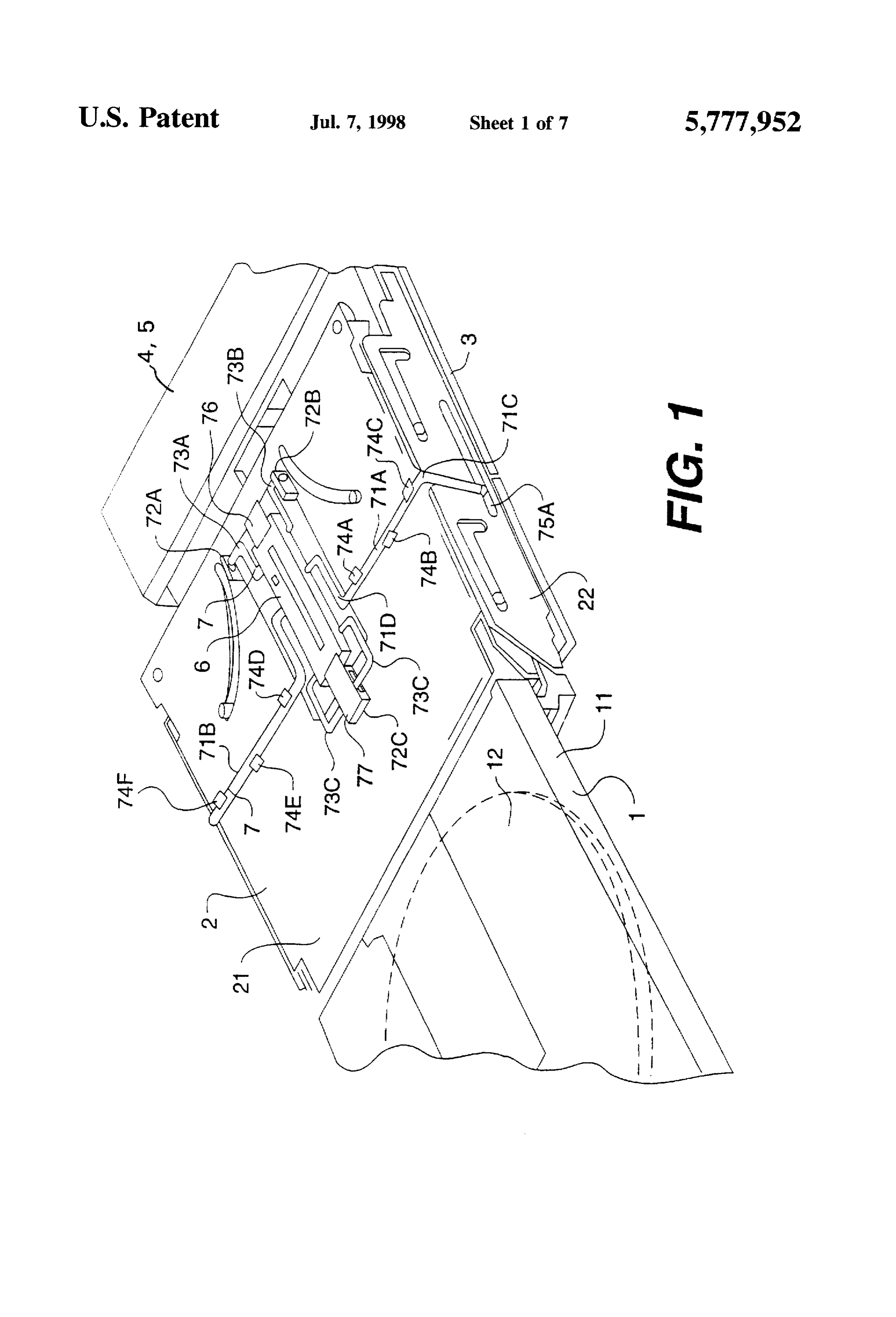
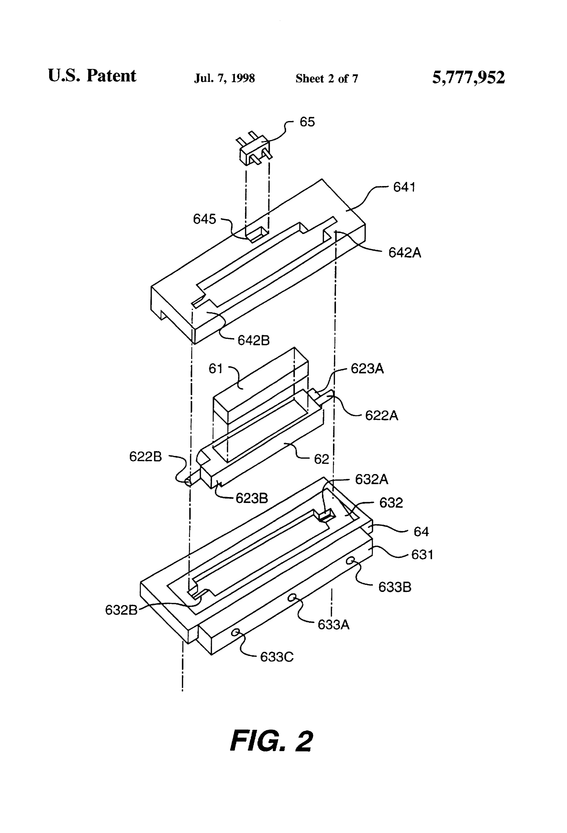
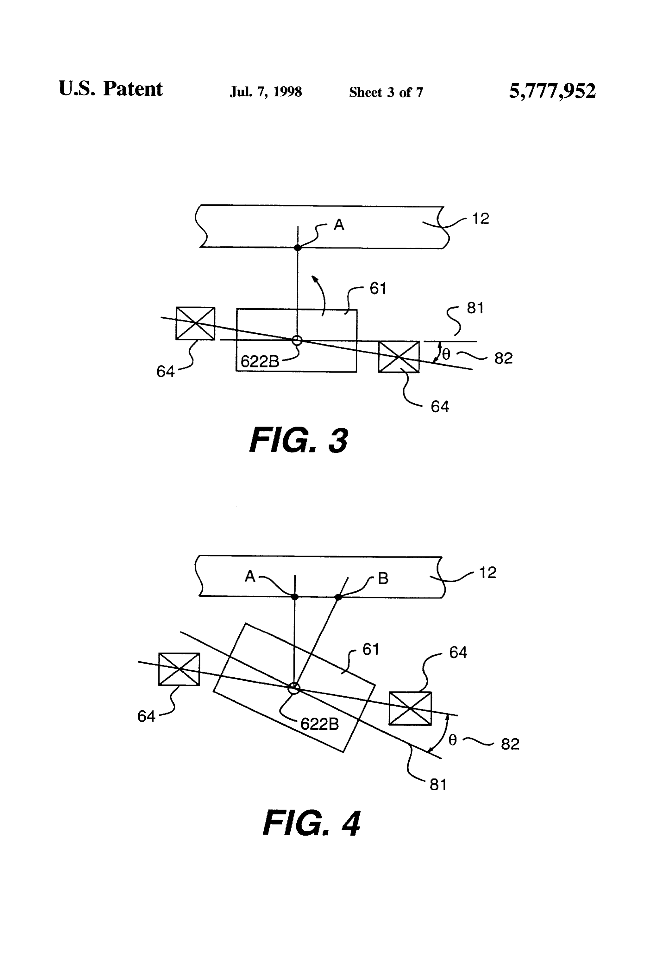
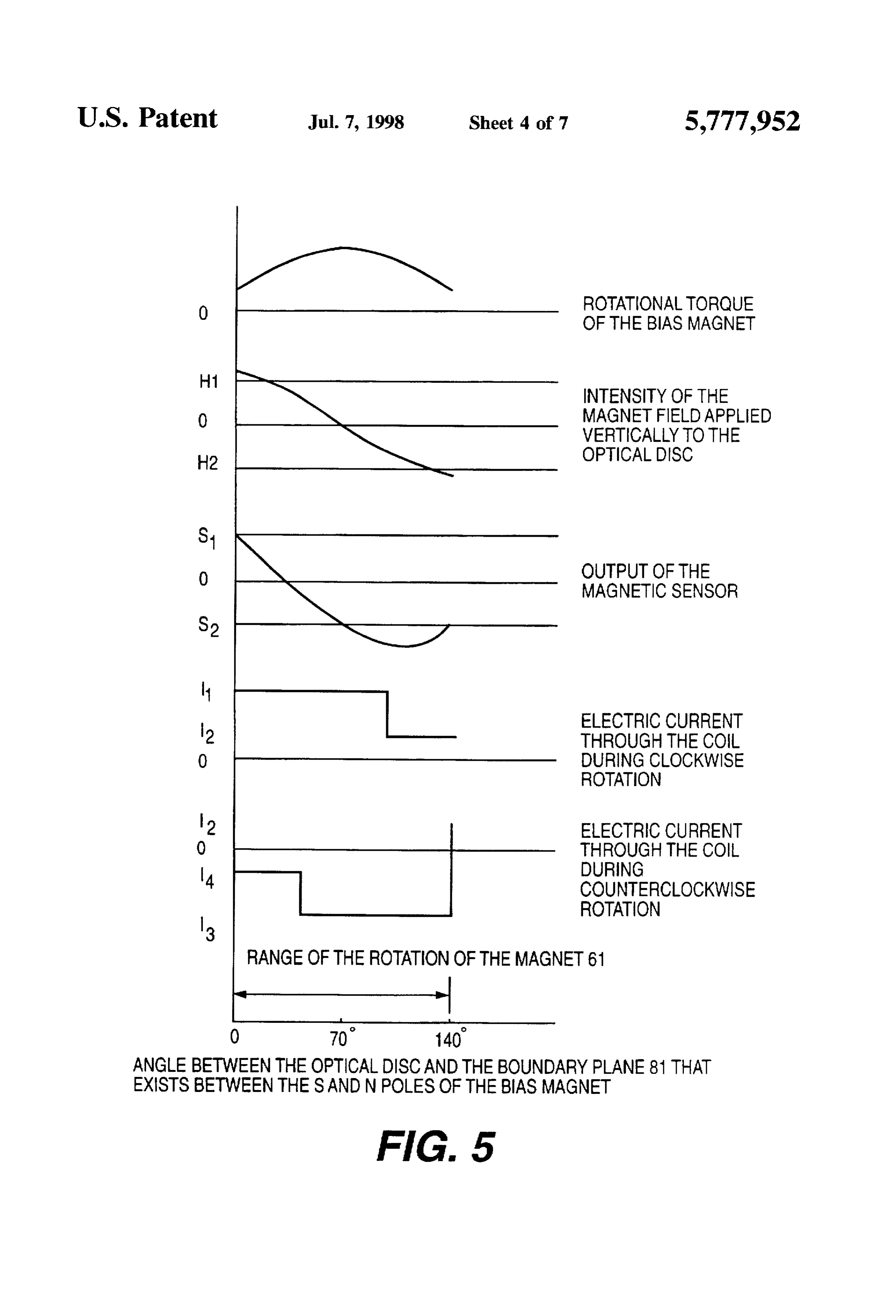
FIG. 2 is an oblique exploded view of the bias magnet; 35 The optical disk cartridge 1 is inserted by an operator FIG. 3 is a cross sectional view showing the relative from a front side of the device, and is first transferred to the positions of the optical disk, the bias magnet and the driving loadingsidemechanism inner of the device by the loading mechanism 2. The 2 horizontally guides the disk cartridge coil during recording or playing back of the data on the with a cartridge holder 21 and then vertically downwardly optical disk; loads the cartridge into the use position. In the use position, FIG. 4 is a cross sectional view showing the relative positions of the optical disk, the bias magnet and the driving the optical disk 12 is supported by a spindle motor and rotated at a predetermined speed. Laser light emitted from a coil during erasing of the data on the optical disk; semiconductor laser passes through an optical head and is FIG. 5 is a multi-wave form graph showing relations formed as an optical spot on a recording part of the disk 12. between the rotational angle of the bias magnet and various 45 Reflected light from the optical disk goes through the optical other parameters; head and is processed by a signal detection in process system FIG. 6 is a partial perspective view showing the relative that is part of the circuit portion 5, not shown in detail. As positions of the magnet and the stoppers during recording of a result, data is able to be recorded and played back on the the data on the optical disk; disk.
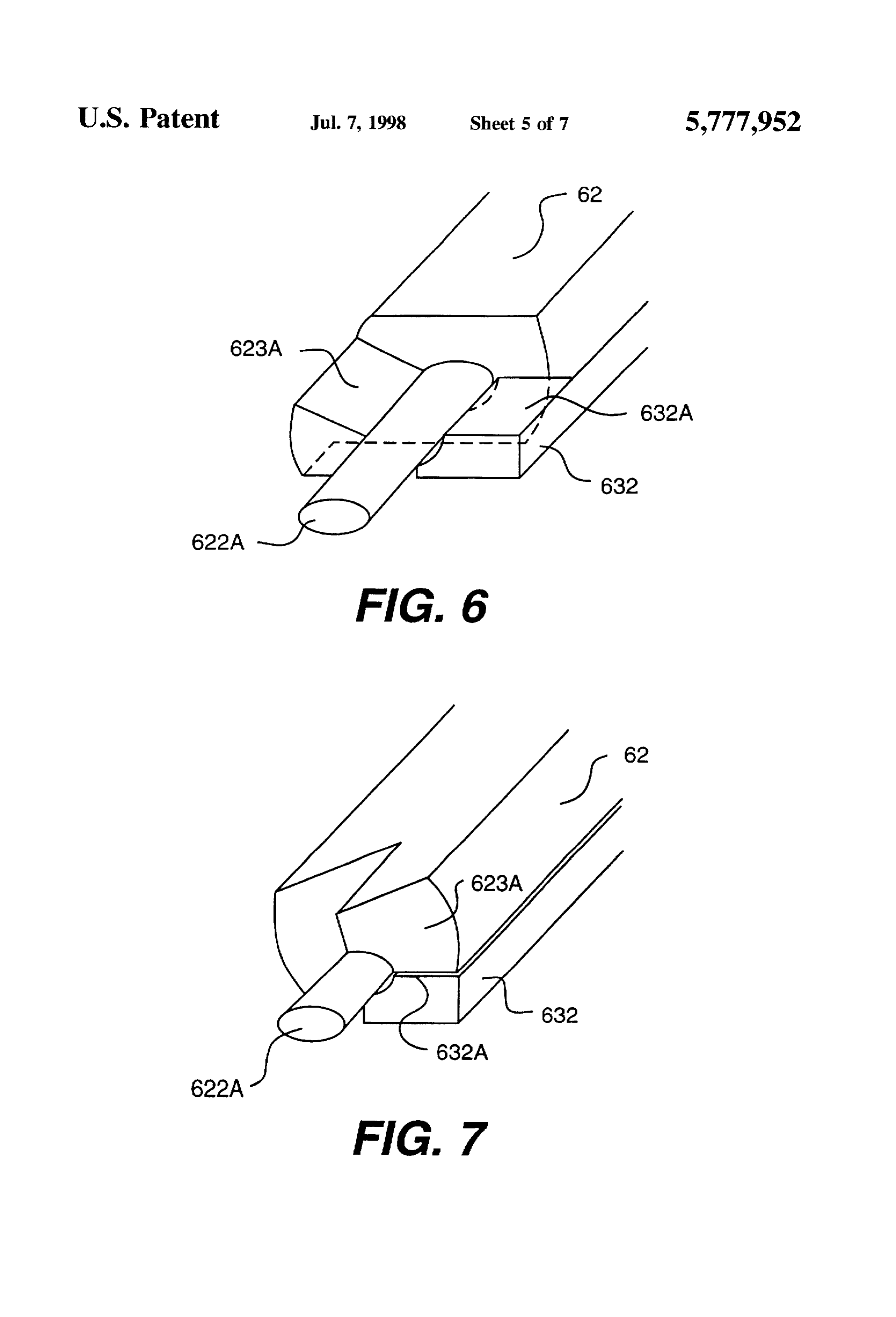
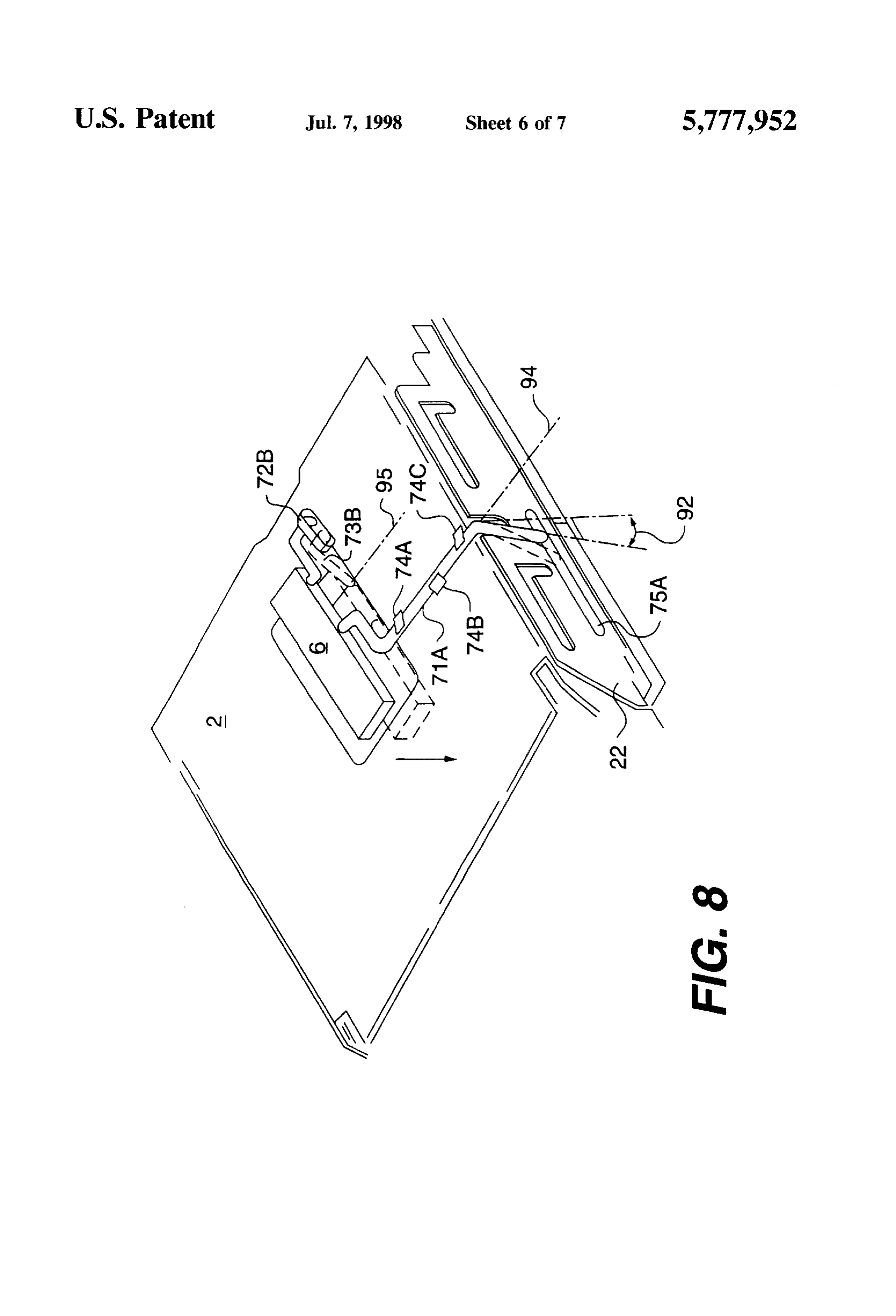
FIG. 7 is a partial perspective view showing the relative 50 FIG. 2 shows the details of the bias magnet 6 in an positions of the magnet and the stoppers during erasing of exploded view. The bias magnet unit includes a magnet 61. the data on the optical disk; which is a permanent magnet preferably having a rectangu FIG. 8 is a partial perspective view useful for explaining lar cross section that is about 2 mm in thickness and about the operation of the up-and-down movement of the bias 2 mm in width, and having an overall length of about 35 mm. magnet; 55The length of permanent magnet 61 is preferably about 5 FIG. 9 is a partial elevational view of the disk device mm longerradius than the difference between a maximum and a before the loading or after the unloading of the optical disk minimum of a recording area on the optical disk Magnet 61 has opposite poles on its planar surfaces wherein cartridge;
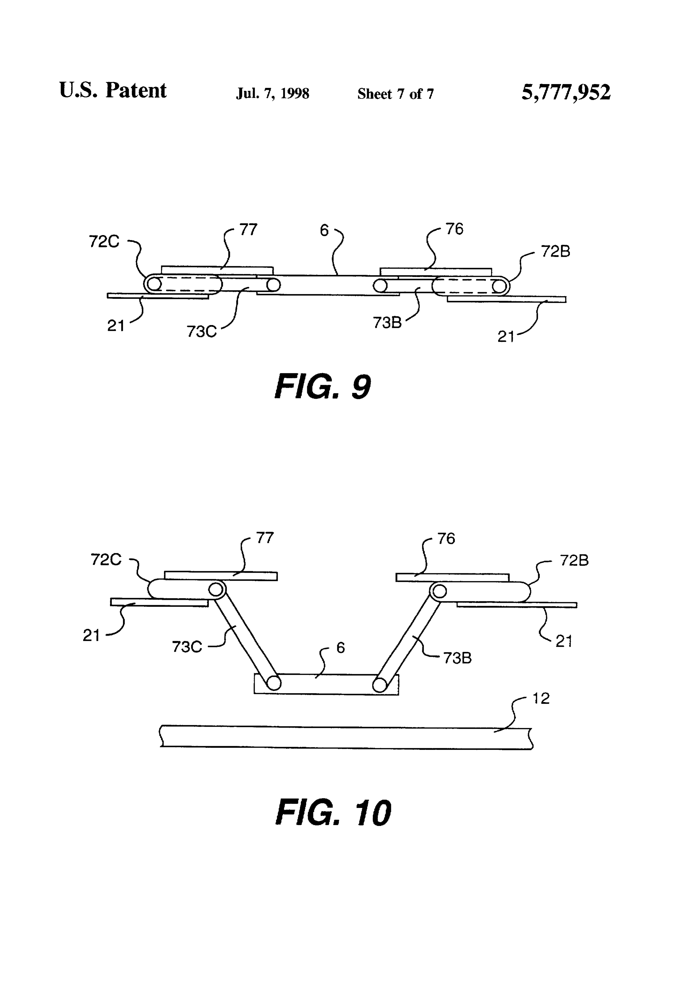
one surface is an Spole and the other surface is an N pole.
FIG. 10 is a partial elevational view of the disk device Accordingly, the permanent magnet is magnetized in the during recording or playing back the data on the optical disk direction of its thickness to provide these opposite poles. DETAILED DESCRIPTION OF THE Magnet 61 is embedded in a center portion of a cap 62. PREFERRED EMBODIMENTS The cap has end shafts 622A and 622B that are received in semicircular grooves 632A and 632B of a magnet holder 632
As set forth herein, the magneto-optical disk device of the 65 to permit rotation of the magnet 61 and cap 62 together. invention is disclosed as having an optical disk disposed or Preferably, the end shafts of cap 62 have a smooth circular horizontally. It is intended that the use of the words outer dimension that is about 1 mm in diameter. The
Page 12
thickness of cap 62 is approximately the same as that of the In FIG. 4, magnet 61 is shown in the position rotated thickness of magnet 61 so that smooth rotation of these about 140 counterclockwise from the position shown in components together is possible. Also, end shafts 622A. FIG.3 for erasing data on disk 12. Stoppers 623A and 623B 622B are preferably coated with a material that permits on cap 62 engage stoppers 632A, 632B and 642A and 642B smooth rotation of the end shafts. to limit the rotational movement of the cap 62. Cap 62 is Cap 62 also has stop 623A and 623B for stopping the prevented from rotating more than about 140° so that the rotational movement of the cap 62 to permit a predetermined boundary plane 81 does not end up being substantially in angular rotation of the cap. The stoppers are arranged line with the mid line passing through the coil 64, in which symmetrically about the rotational axis of the cap 62. A case there would be a very limited amount of rotating torque detailed disclosure of stopper 623A and 623B is set forth O generated upon excitation of the coil 64. In other words, the hereinafter with respect to FIGS. 6 and 7. rotation of cap 62 is limited to prevent the cap from reaching Magnet 61 is supported for rotational movement about the a neutral position in which rotation in either direction would shaft end 622A, 622B by magnet holders 631. 632 and 641.
Magnet holders 631 and 641 have a flat shape that is longer be FIGS. made difficult merely by driving the cap with the coil 64. 6 and 7 show the details of the relation between the than magnet 61 in width and in length. The semicircle 15 stoppers and groove portions 632A, 632B formed in magnet holder 632 of magnet capthe62.magnet In holder 632 by reference to one side particular, a stopper 623A of cap 62 is are complemented by upper semicircular grooves 642A, 642B formed in magnet holder 641. Together the semicircle shown in FIG. 6 to be in the position schematically repre portions respectively support shaft end 622A, 622B in sented in FIG. 3. After rotation of about 140°, clockwise as rotation as bearing surfaces for the shaft ends. shown in the transition between FIGS. 6 and 7, the stopper Magnet holders 631 and 641 sandwich the cap 62 to 623A engages the above surface 632A of magnet holder 632. support rotational movement of the cap therebetween. FIG. 5 is a multiwaveform graph showing the values of Preferably, each of the magnet holders 631 and 641 is one various variables in relation to the degree of angular rotation half of the thickness of the permanent magnet. i.e. each of of the magnet 61 in the transition between the positions of the magnet holders is approximately 1 mm in thickness. As magnet 61 shown in FIGS. 3 and 4. These variables include a result, when the magnet holder 631 and 641 are assembled 25 the rotational torque of the bias magnet, the intensity of the together they have a similar thickness of that with cap 62. magnetic field applied vertically to the optical disk, the Cap 62 and magnet 61 rotate to provide the polarity output of the magnetic sensor 65, the electric current flowing change in the magnetic field that is applied to the disk 12. through the coil during clockwise rotation and the electric For rotating cap 62 and consequently magnet 61, a driving current flowing through the coil during counterclockwise coil 64 is provided as shown in FIG. 2, and as schematically 30 rotation of the magnet 61.
shown in FIGS. 3 and 4. As shown, driving coil 64 is angularly offset from being parallel to the surfaces of magnet A current I1 is added to the driving coil 64 when the 61. Coil 64 is shown as being fixed to magnet holders 631 magnet starts to rotate, as shown in FIG.5. Then the rotation and 632. and at one side of magnet holder 631, coils of the cap 62 and magnet 61 is accelerated. During the 633A-633C are provided, in which are received the ends or 35 acceleration, the current is reduced to I2, as shown, or tips of arms 71A, 73B and 73C. respectively, as shown in reversed in its direction temporarily in order to decelerate FIG. 1. On the opposite side of the magnet holder 631, three the rotational speed and to alleviate the shock of the engage similarly positioned holes (not shown) are provided in which ment between the stoppers. Reversing the direction of the are received the tops or ends of arms 71B.73A and 73D. The current is an effective method to decrease the shock. After arms of the magnet positioning structure are described in the magnet stops rotating, a minimum current level I2 is greater detail with reference to FIGS. 8-10. maintained to keep the magnet in its position with the As shown in FIG. 2, a magnet sensor 65 that detects the stopper 623A and 623B engaging the surfaces 632A and polarity of the applied magnetic field and the rotational 632B and 642A and 642B, respectively.
angle of the magnet 61 from the intensity of the magnetic When the magnet is rotated in the reverse direction, a field is mounted in a socket 645 provided in magnet holder 45 current I3 is generated in driving coil 64 and the magnet 641. The sensor is mounted on a small, thin circuit board that starts to rotate in the reverse direction. During acceleration is not shown in the drawings. in reverse, the current is reduced to I4, as shown or the The cap 62 and bias magnet 61 rotate by the interaction direction of the current is reversed temporarily. After the between the electric current flowing through the driving coil magnet stops rotating, current level I4 is maintained in coil 64 and the magnetic field generated by magnet 61. The 50 64 to keep the magnet 61 in the position shown in FIG. 3. polarity reversing of the magnetic field applied to the disk is FIG. 5 also shows the output of the sensor 65. When the attained by rotating the cap 62. The cap 62 rotates from an magnet stops at either of the positions shown to be at 0 or initial position shown in FIG. 3, for example, at 0° to about 140°, the output of the sensor reaches the values S1 or S2. 140° in the counterclockwise direction until reaching the respectively. Therefore, the magnetic sensor 65 detects position shown in FIG. 4. 55 whether or not the magnet has stopped at one of the FIGS. 3 and 4 show the relative positions of the disk 12. predetermined angular positions or not by monitoring the driving coil 64 and bias magnet 61, schematically. During output of the sensor. If the output is within a predetermined loading or unloading of the optical disk cartridge 1 and range around the normal values, Si or S2, a stop position is during data recording, the magnet 6 is in the position determined to be confirmed.
shown in FIG. 3. Stoppers 623A and 623B, shown in FIG. FIG. 9 shows that the lower surface of the bias magnet 6 2, for example, are arranged so that the boundary plane 81 is at nearly the same height as the upper surface of the between the S and N poles of the magnet 61 is nearly in cartridge holder 21. The bias magnet 6 is arranged above the parallel to the optical disk when the magnet 61 is in the FIG. cartridge holder and a venting hole is arranged at the upper 3 position. A main plane that includes the center or mid surface of the cartridge holder for the up and down move portion of the driving coil 64 is angularly offset with respect 65 ment of the bias magnet 6. During loading and unloading of to boundary plane 81 by an angle 0, which is preferably the optical disk cartridge 11, the boundary plane 81 of about 20. magnet 61 is nearly in parallel to the optical disk 12.
Page 13
As shown in FIGS. 3 and 4, and as discussed above, the and 72B. These plates are positioned so that the lower magnet 61 rotates approximately 140° so that its surface is surface of the bias magnet 61 equals the level of the upper not parallel with the optical disk 12 when in the erase position shown in FIG. 4. Accordingly, an optical spot A, surface of the cartridge holder 21, as shown in FIG. 9. which is along a line perpendicular to plane 81, directly is shown withofrespect
Movement the bias magnet by the linkage structure 7 above magnet 61, as shown in FIG. 3. is not subjected to the partial perspective viewtothat FIG.8. FIG. 8 is a simplified or discloses only the arms 71A, same magnetic field of opposite polarity when the magnet 61 is shifted to the position shown in FIG. 4. The reason for this the stopper arm 73B and the slot portion 72B. When an is that the surface of magnet 61 is shown in FIG. 4. In other operator inserts an optical disk cartridge 11 into the words, for a point "A", the intensity of the bias magnetic magneto-optical disk device, the cartridge 11 is held by the field applied vertically to the optical disk during erase is 10 cartridge holder 21 and a loading motor and corresponding smaller than the intensity of a magnetic field applied during mechanism (not shown) transfers the cartridge holder 21 recording (FIG. 3). Therefore, an adjustment is made before horizontally into the interior of the device. After confirming assembly to shift the point on the magnetic disk that is to be an end of the horizontal transfer operation of the cartridge recorded on or played back from and erased, depending holder 21 by a sensor (not shown) the cartridge holder 21 upon the position of magnet 61. Such a shifted point "B" is 15 descends. During the descent, the tip of the arm 71A, which shown in FIG. 4, for example. The position of point "B" is is engaged in the slot 75A of the side cover 22, is driven by determined by insuring that the intensity of the magnetic a vertical upward force applied through slot 75A. This field applied to the point A in FIG. 3 is the same as that causes rotation of arm 71A around an axis of rotation 94. applied to the point B in FIG. 4, however of opposite which is a shaft of the arm for an angle of rotation 92 polarity. The optical spot is shifted prior to or in the process measured with respect to a perpendicular or vertical line that of assembly of the device so that the intensity of the vertical is perpendicular to the surface of cartridge holder 21. The tip component of the magnetic field at the optical spot during of the arm 71 is moved horizontally along slot 75A by the erasing becomes substantially equal to or similar to that of upwardly generated force, which makes arm 71A rotate the intensity of the vertical component of the magnetic field 25 thereby increasing angle 92. Consequently, clockwise during recording. rotation, as viewed in FIG. 8, is produced resulting in Alinkage structure 7 moves by its magnet 6 up and down. magnetshows 6 being driven in descent. Accordingly, FIG. 8 the down position in dashed lines and the upposition and is explained as follows with respect to FIG. 1. In particular, linkage structure 7 includes arms 71A and 71B. in solid lines.
which are arranged oppositely of one another on each side According to the descent of the bias magnet 6, the stopper of magnet 6 and supported, respectively, by bearing 74A. arm 73B rotates around an axis of rotation 95, which is a 74B, 74C and 74D, 74E and 74F The bearings, which are pivoting center of arm 73B. The tip of the stopper arm 73B, mounted on the cartridge holder 21 permits smooth rota which is engaged with the slot 72B moves horizontally tional movement of the arms. At each end of arms 71A, 71B along the slot 72B to the end of the slot closest to the center are L shaped portions. In FIG. 1 the L shaped portions 71C 35 of the device as the arm rotates. The end portion of the slot and 71D are shown for arms 71A, and the arm 71B is 72B stops the horizontal movement of the tip of the stopper arranged symmetrically with respect to arms 71A. A right arm 73B and consequently rotational movement of the angle bend is provided at the terminal portion of L shaped stopper arm 73B so that the descent of the bias magnet 6 is arm portion 71D and the top of the arm 71A is received with stopped. It is understood that this action is also achieved a hole 633A shown in FIG. 2 of magnet holder 631. A similar through the arm and slot combinations of arms 73A and 73C arrangement is provided for arm 71B on the other side of the and the respective slot 72A and 72C, although these arms magnet 6. At the other end portion of arm 71A, the tip of the and slots are not shown in FIG. 8.
arm of L shaped art portion 71C, the return bend or right FIG. 10 is a partial elevational view showing the relative angle bend enables the end or top of arm 71A to be received positions of the bias magnet 6 (61). the cartridge holder 21. within an elongated slot 75A. Although the arrangement for 45 the optical disk 12, the stopper arms 73B and 73C. The arm arm 71A is shown in detail is the perspective view of FIG. 71A and connection point to magnet 6 through hole 633A 1, it is understood that arm 71B has a similar arrangement, formed in magnet holder 631 is not shown in FIG. 10. including the provision of an elongated slot opposite to slot The unloading operation is performed similarly to the 75A that is formed in the side cover 22. loading operation, except that the cartridge holder 21 moves As shown in FIG. 2. magnet holder 631 also has holes 50 vertically upwardly or ascends. A vertical downward force 633B and 633C which receive, respectively, the ends of arms pushes the top of the arms 71A, which is engaged in slot 73A, 73B and 73C. The opposite ends of each of these arms 75A. The tip of the arm 71A moves along the slot 75A are respectively received in elongated slots 72A, 72B and horizontally to the inner side of the device. Therefore, the 72C. During descent of the magnet 6, the end portions distal arm 71A rotates counterclockwise around the axis of rota from magnet 6 of arms 72A-72C travel in respective slots 55 tion 94 and the bias magnet 6 ascends. The thin plates 76 and 72A-C until the respective ends of these slots are engaged 77 are arranged to stop the ascent of the bias magnet in the by the arms and the magnet can descend no further. position, as shown in FIG. 9. This leaves the lower surface According to the arrangement of arms of linkage structure of the bias magnet 61 to be approximately equal with the 7, the linkage does not occupy a great amount of space in the upper surface of the cartridge holder 21, thereby providing vertical direction on the cartridge holder 21. Further, the bias clearance for the removal of magneto-optical disk cartridge magnet 6 moves vertically smoothly. It is clear from FIG. 1 11.
that the length of the slots 72A-72C is longer than the The linkage structure that drives the bias magnet up and distance between the holes 633B and 633C of magnet holder down, according to the present invention, is thin enough to 631. be arranged between the device cover and the cartridge To stop the ascent of magnet 6 in the upward direction, 65 holder. When an operator inserts the optical disk cartridge protruding thin plates 76 and 77 are arranged opposite one into the magneto-optical disk device, a thin bias magnet another on the upper part of slots 72C and between slots 72A arranged between the device cover and the cartridge holder
Page 14
descends to a position adjacent or near to the recording spot a stopper for limiting a rotational angle through which of the optical disk by the aforementioned structure providing said magnet rotates so that a boundary place between the up and down movement. When the operator rejects the an Spole and an Npole of said magnet is not in parallel optical disk cartridge, the bias magnet is repositioned into with a plane of said optical disk in a stopped position the space between the device cover and the cartridge holder. of said magnet;
thus allowing the cartridge to be removed. a linkage structure for moving said magnet up and down The driving coil, the magnetic sensor and the magnetic including a pair of support arms, each having a central holder, as well as the structure providing the up and down linear portion pivoted by bearings on an upper surface movement of the magnet can be arranged, according to a of said cartridge holder; and preferred embodiment of the invention, within a space of a O each said support arm further having first and second thickness of about 2 mm. The profile of these components is L-shaped portions at opposite end portions thereof, and shown in FIG. 9 to be very thin. Accordingly, the height of a first tip at one end of said support arm adjacent said the magneto-optical disk device can be decreased, which first L shaped portion that is engaged with a first hole decreases the overall size of the device, thereby making the provided on a side of said bias magnet unit and a magneto-optical disk device more compact. 15 second tip at the other end of said support arm adjacent Further, the electric current that flows through the driving said second L shaped member that is engaged with a coil is low when the coil rotates the bias magnet or when it first slot that is arranged on said side cover; is stopped. Still further, since the structure providing the up wherein, for each said support arm, movement of said and down movement of the bias magnetis mainly comprised second tip in said slot causes rotational movement in of the linkage structure 7 that does not require special motors said central linear portion to move up and down said or gears to transfer the bias magnet, the device of the present first tip by movement of said first L shaped portion that invention can be assembled easily and function efficiently causes up and down movement of said bias magnet with small power consumption. unit.
We claim: 3. A magneto-optical disk device according to claim 2. 1. A magneto-optical disk device having a housing includ 25 further including:
ing a base and a side cover fixed to said base, a cartridge stopper arms arranged on opposite sides of said support holder for holding and transferring an optical disk cartridge. arms and second and third slots arranged on an upper a spindle motor that rotates an optical disk in said optical surface of said cartridge holder, said stopper arms at disk cartridge, and an optical head that projects an optical 30 one end thereof engaging second and third holes in spot onto a recording or playing back portion of an optical sides of said magnet unit and engaging at the other end disk, comprising: thereof said second and third slots; a loading mechanism that transfers said optical disk wherein a distance between said second and third slots is cartridge, when held by said cartridge holder, between longer than a distance between said second and third an entry/exit position and a playing position by trans 35 holes of said bias magnet unit, ferring said cartridge vertically; whereby a descent position of said magnet unit is limited a bias magnet unit that includes a permanent magnet that by said stopper arms when said loading mechanism applies a bias magnetic field to said projected optical drives said cartridge holder vertically to said playing spot, a driving coil that rotates said permanent magnet position.
in order to switch a polarity of said bias magnetic field 4. A magneto-optical disk device according to claim 3, as applied to said projected optical spot. and a sensor to further including protruding stoppers on one of said car detect said polarity of said bias magnetic field; tridge holder and said bias magnet unit for stopping an said driving coil of said magnet and said sensor are ascent of said bias magnet unit at a position where a lower arranged within a thickness of said magnet with respect surface of said bias magnet unit is level with said upper to a thickness direction of said optical disk; and 45 surface of said cartridge holder.
a stopper for limiting a rotational angle through which 5. A magneto-optical disk device according to claim 4. said magnet rotates so that a boundary plane between wherein said linkage structure has a thickness nearly equal an Spole and an Npole of said magnet is not in parallel to a thickness of said magnet unit during a loading/ with a plane of said optical disk in a stopped position unloading position.
of said magnet. 50 6. A magneto-optical disk device according to claim 1. 2. A magneto-optical disk device having a housing includ wherein a plane that goes through said optical spot and ing a base and a side cover fixed to said base, a cartridge crosses vertically said optical disk, does not correspond to a holder for holding and transferring an optical disk cartridge, plane that goes through a rotational axis of said magnet and a spindle motor that rotates an optical disk in said optical crosses vertically said optical disk, and disk cartridge. and an optical head that projects an optical 55 said optical spot is shifted horizontally and appropriately spot onto a recording or playing back portion of an optical so that an intensity of said bias magnetic field during disk, comprising: erasing data, is approximately equal to an intensity of a loading mechanism that transfers said optical disk said bias magnetic field during recording of said data. cartridge, when held by said cartridge holder, between 7. A magneto-optical disk device having a housing includ an entry/exit position and a playing position by trans ing a base and a side cover fixed to said base, a cartridge ferring said cartridge vertically; holder for holding and transferring an optical disk cartridge. a bias magnet unit that includes a permanent magnet that a spindle motor that rotates an optical disk in said optical applies a bias magnetic field to said projected optical disk cartridge, and an optical head that projects an optical spot, a driving coil that rotates said permanent magnet spot onto a recording or playing back portion of an optical in order to switch a polarity of said bias magnetic field 65 disk, comprising:
as applied to said projected optical spot, and a sensor to a bias magnet for applying a magnetic field to said optical detect said polarity of said bias magnetic field; disk at said optical spot;
Page 15
a stopper for limiting a rotational angle through which a sensor in said linkage structure that detects a polarity said magnet rotates so that a boundary place between and an intensity of said magnetic field. an S Pole and an N Pole of said magnet is not in parallel 12. A disk device according to claim 10, further com with a plane of said optical disk in a stopped position prises:
of said magnet; a side cover that is fixed to a base of said device and that a linkage structure mounted on said cartridge holder in a faces a side of said cartridge holder. space at a center of the cartridge holder that moves the 13. A disk device having a housing including a base and bias magnet up and down; a side cover fixed to said base, a cartridge holder for holding said linkage structure including arms that rotate around an 10 and transferring an optical disk cartridge, a spindle motor axis that are secured on said cartridge holder. that rotates an optical disk in said optical disk cartridge, and 8. A disk device according to claim 7, further comprises: an optical head that projects an optical spot onto a recording a sensor in said linkage structure that detects a polarity or playing back portion of an optical disk, comprising: and an intensity of said magnetic field.
9. A disk device according to claim 7. further comprises: 15 a permanent medium in magnet that applies a magnetic field to a disk said disk cartridge;
a side cover fixed to a base of said device and that faces a side of said cartridge holder. a stopper for limiting a rotational angle through which 10. A disk device having a housing including a base and said magnet rotates so that a boundary place between a side cover fixed to said base, a cartridge holder for holding an Spole and an Npole of said magnet is not in parallel and transferring an optical disk cartridge, a spindle motor 20 with a plane of said optical disk in a stopped position that rotates an optical disk in said optical disk cartridge, and of said magnet;
an optical head that projects an optical spot onto a recording a linkage structure mounted on said cartridge holder in a or playing back portion of an optical disk, comprising: space at a center of the cartridge holder that moves the a permanent magnet that applies a magnetic field to a disk bias magnet up and down;
medium in said disk cartridge; 25 a loading mechanism that transfers said disk cartridge a stopper for limiting a rotational angle through which horizontally and vertically from a loading position to a said magnet rotates so that a boundary place between playing position together with said cartridge holder; an S Dole and an Npole of said magnet is not in parallel said linkage structure including arms that rotate according with a plane of said optical disk in a stopped position to said vertical transfer of said disk cartridge around of said magnet; 30 axes that are secured on said cartridge holder.
a linkage structure mounted on said cartridge holder in a 14. A disk device according to claim 13, further com space at a center of the cartridge holder that moves the prises:
bias magnet up and down; a sensor in said linkage structure that detects a polarity a driving coil in said linkage structure that rotates said 35 and an intensity of said magnetic field. permanent magnet in order to switch a polarity of said 15. A disk device according to claim 13, further com magnetic field; and prises:
said linkage structure including arms that rotate around an a side cover that is fixed to a base of said device and that axis that are secured on said cartridge holder. faces a side of said cartridge holder. 11. A disk device according to claim 10, further com prises: :: k -k sk xk
Provenance
- Collection
- Cited prior art
- Original PDF
- patentimages.storage.googleapis.com →
- Filed
- 1996-07-11
- Pages
- 15
- Method
- pdftotext (the PDF's own text layer) + pdftoppm 300dpi page scans
- Source
- Google Patents bibliographic record
- Granted
- 1998-07-07
- Inventors
- Hajime Nishimura; Atsushi Ichikawa; Akio Yabe; Yuji Yokoyama; Hitachi Computer Peripherals Co Ltd; Hitachi Ltd
- Transcribed from
- patentimages.storage.googleapis.com →