patent · US6246126
Hooded wind power engine
12 June 2001
Page 1 — bibliographic record
(12) United States Patent (10) Patent No.: US 6,246,126 B1 Van Der Veken et al. (45) Date of Patent: Jun. 12, 2001
(54) HOODED WIND POWER ENGINE 4.324,985 4/1982 Oman ..................................... 290/55 4,396,843 8/1983 Martinez Parra ...................... 290/55 (75) Inventors: Germaine Van Der Veken, 4,411,588 10/1983 Currah, Jr. ........... . 41.5/2 A St.-Jans-Molenbeek (BE); Pierre 4,808,068 2/1989 Asbjornson et al. 415/157 Martinet, St.Etienne (FR); Jozef 4,859,140 * 8/1989 Passadore ............. ... 41.5/48 Adriaenssens, Antwerpen (BE) 5,035,611 * 7/1991 Neubecker et al. ................. 432/176 5,827,044 * 10/1998 Yazici et al. ......................... 415/132 (73) Assignee: Germaine Van Der Veken, St.-Jans. FOREIGN PATENT DOCUMENTS Molenbeek (BE) 44 28 730 2/1996 (DE).
(*) Notice: Subject to any disclaimer, the term of this 2317522 2/1977 (FR). patent is extended or adjusted under 35 873173 7/1961 (GB).
U.S.C. 154(b) by 0 days. 3323-200-A 1/1985 (GB) ..................................... 415/4.5 (21) Appl. No.: 09/449,524 * cited by examiner (22) Filed: Nov. 29, 1999 Primary Examiner Nicholas Ponomarenko (74) Attorney, Agent, or Firm-Bacon & Thomas, PLLC
Related U.S. Application Data (57) ABSTRACT
p of application pp No. 09/284.830, filed as Wind engine device consisting of a wind power engine (2) application No. PCT/BE97/00122 on Oct. 21, 1997. and means (3) to increase the wind Velocity in the direction (30) Foreign Application Priority Data of the wind power engine (2) when the wind Velocities are low, whereby these means (3) contain at least a first wind
Oct. 22, 1996 (FR) ... guiding element (5) which narrows in a conical manner Mar. 4, 1997 (CH) ................................................... 0510/97 according to the direction in which the wind (W) blows (51) Int. Cl." .................................................... F03D 1700 towards the wind power engine (2), characterized in that this (52) U.S. Cl. ................................................. 290/55; 290/44 device (1) contains means (4) which make it possible to (58) Field of Search ......................... 290/44, 55; 41.5/21, diminish the wind Velocity, the wind force respectively, on 415/1, 48 the place where the wind power engine (2) is situated, which contain a second wind guiding element (9) which joins the (56) References Cited exit (7) of the first element and which widens in a conical manner according to the direction in which the wind blows
1,345,022 6/1920 Oliver. power engine (2) and the Second wind guiding element (9) 3,192,712 7/1965 Nash et al. ............................ 60/35.6 in relation to one another, Such that the wind power engine 3,883,750 5/1975 Uzzell, Jr. .. ... 290/55 (2) slides in further or less further in the second wind 4,047,832 9/1977 Sforza ... ... 415/1 guiding element (9).
4,079,264 3/1978 Cohen .................................... 290/55 4,260,325 4/1981 Cymara ................................ 415/2 R 10 Claims, 3 Drawing Sheets
Page 2
Drawing sheet — no readable text.
Page 3
Drawing sheet — no readable text.
Page 4
Drawing sheet — no readable text.
Page 5
HOODED WIND POWER ENGINE diameter at the entry 6 and at the exit 7 of this element 5, in particular the diminution of the diameter, produces an
This Application is a continuation-in-part of Ser. No. increase of the wind velocity in the direction of the rotor 8 09/284,830 filed Jun. 17, 1999 which is a 371 of PCT/BE97/ of the wind power engine 2.
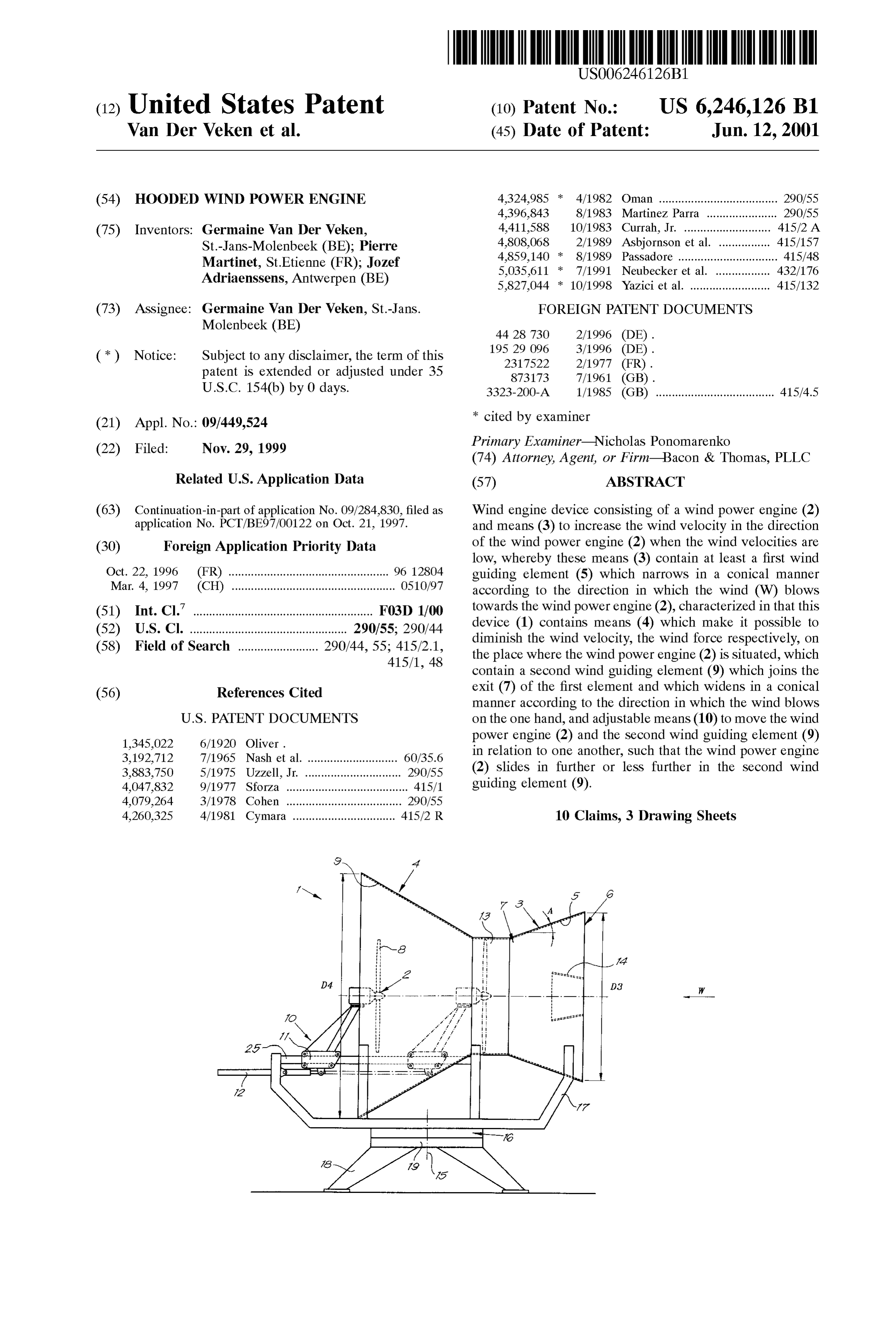
100122 Oct. 21, 1997. The means 4 for diminishing the wind velocity, the actual The present invention concerns a wind engine device. wind force respectively, on the place where the wind power In particular, the invention concerns a device consisting engine 2 is situated, contain a Second wind guiding element of a wind power engine and means to increase the wind 9 on the one hand which joins, either directly or indirectly, Velocity towards the wind power engine when Said wind the exit 7 of the first element 5 and which widens conically Velocity is low, whereby these means contain at least a first according to the direction in which the wind blows, and wind guiding element which narrows in a conical manner means 10 on the other hand which make it possible to move according to the direction in which the wind blows towards the wind power engine 2 and the Second wind guiding the wind power engine. element 9 in relation to one another, Such that the wind A wind engine device of this type is known from docu power engine 2 slides in further or less further in the Second ment U.S. Pat. No. 3,883,750. However, this document does 15 wind guiding element 9.
not disclose a Solution which makes it possible to provide for In the embodiment represented in FIG. 1, the wind an optimal adjustment as a function of the wind Velocities, guiding element 9 is fixed and the above-mentioned means i.e. an adjustment which makes it possible to increase the 10 are composed of a carriage 11 upon which the wind effect of the wind on the wind power engine in case of a power engine 2 is mounted and of drive means 12 to move gentle breeze and to diminish Said effect in case of a Strong the carriage 11.
breeze. In the given example, these drive means 12 are composed The invention aims a wind engine device which does not of one or Several hydraulic pressure cylinders which may be have the above-mentioned disadvantage and which is par automatically controlled depending on the requirements of ticularly efficient with low wind velocities as well as with the wind power engine. However, it is clear that, according high wind Velocities. 25 to a variant, the drive may be of a mechanical, electric or To this end, the invention concerns a wind engine device other nature.
consisting of a wind power engine and means to increase the Naturally, according to a variant, the wind power engine wind Velocity in the direction of the wind power engine 2 can be mounted in a fixed manner, whereas the wind when the wind velocities are low, whereby these means guiding element 9 can be moved, either with or without the contain at least a first wind guiding element which narrows wind guiding element 5.
in a conical manner according to the direction in which the It should be noted that the wind power engine 2 has a wind blows towards the wind power engine, characterized in rotor diameter which corresponds more or less to the diam that this device contains means which make it possible to eter of the passage between the first and the Second Wind diminish the wind Velocity, the wind force respectively, on guiding element, 5 and 9 respectively. the place where the wind power engine is situated, which 35 AS represented in FIG. 1, a cylindrical connecting piece contain a Second wind guiding element which joins the exit 13 can be provided.
of the first element and which widens in a conical manner It should be noted that the input diameter D3 is smaller according to the direction in which the wind blows on the than the output diameter D4.
one hand, and adjustable means to move the wind power The wind always increases inside the wind guiding engine and the Second wind guiding element in relation to 40 element 5, with low wind velocities as well as with high one another, Such that the wind power engine Slides in wind velocities. As the diameter D4 is larger than the further or less further in the Second wind guiding element. diameter D3 and the wind power engine 2 can be moved, the In order to better explain the characteristics of the wind can be diminished as well as increased inside the wind invention, the following preferred embodiments are power engine, compared to the outside wind.
described as an example only without being limitative in any 45 AS indicated in FIG. 1, the guiding element 5 may way, with reference to the accompanying drawings, in possibly be equipped with a guiding piece 14 which widens which: conically.
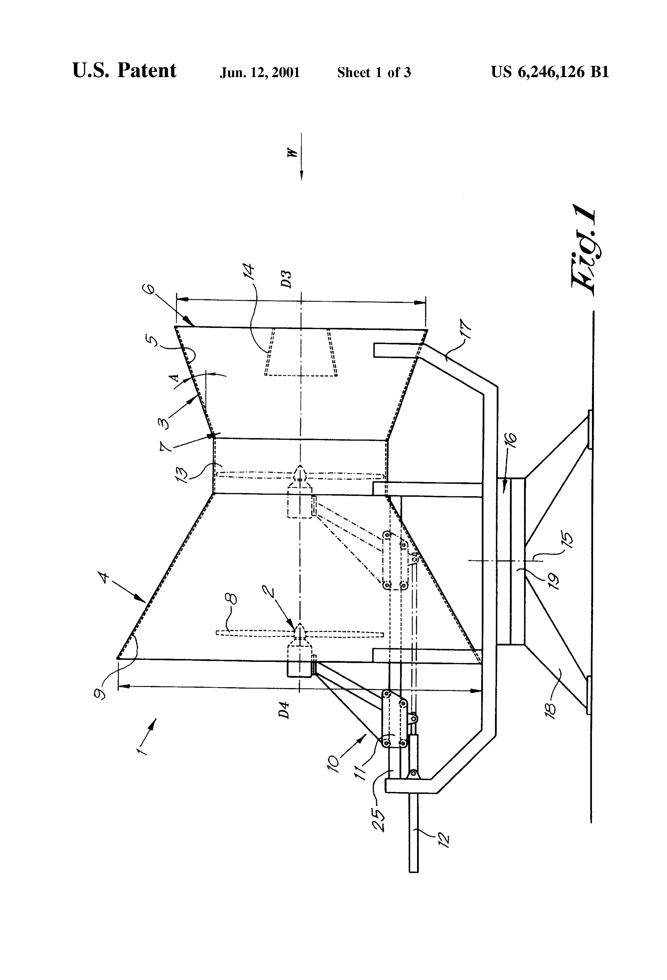
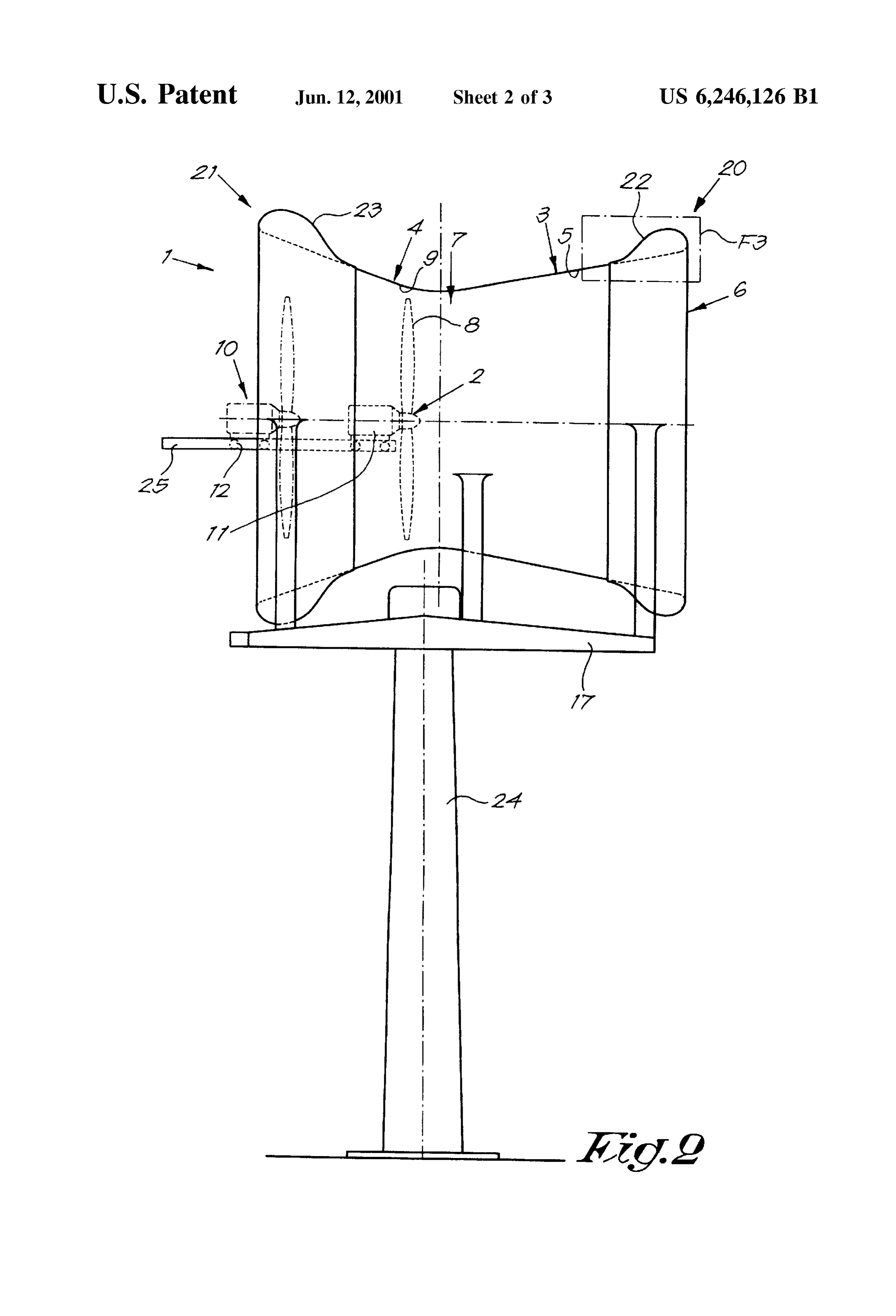
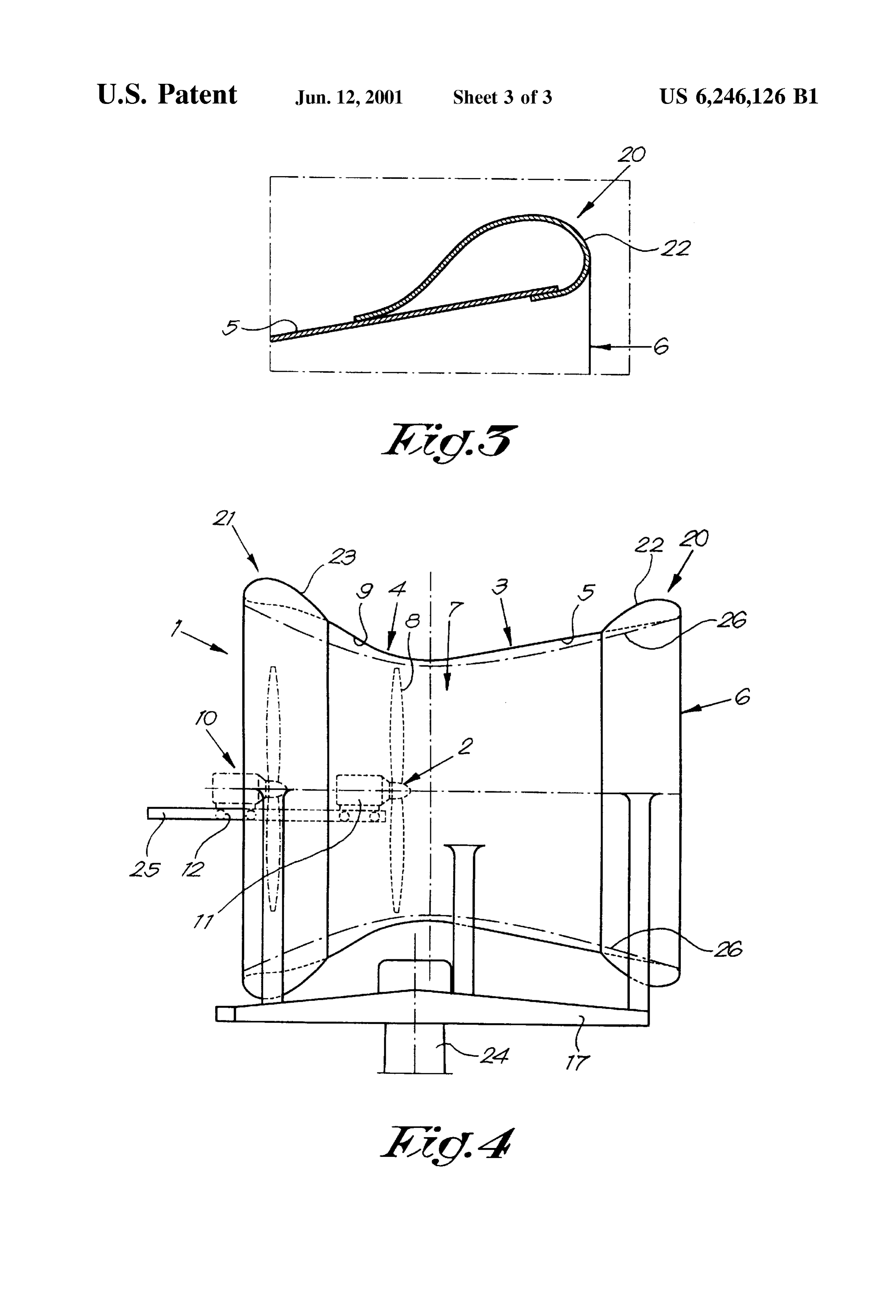
FIG. 1 represents a wind engine device according to the The whole can preferably rotate around a vertical shaft invention; 15 which is equipped with drive means 16 to place it in the FIG. 2 represents a variant of the invention; 50 wind. The wind power engine 2 and the wind guiding FIG. 3 shows a section of the part indicated by F3 in FIG. elements 5 and 9 are mounted on a frame 17 to this end 2 to a larger Scale; which is placed in a revolving manner on a fixed Support FIG. 4 represents another variant of the invention. 18-19.
As represented in FIG. 1, the wind engine device 1 The working can be easily derived from FIG. 1. according to the invention mainly consists of the combina 55 Preferably, the whole is always placed facing the wind tion of a wind power engine 2, means 3 to increase the wind and it is maintained in the wind by means of the driving Velocity in the direction of the wind power engine 2 when means 16, which may be automatically controlled as a the wind Velocities are low, and means 4 to influence, in function of the data of a measuring instrument which particular diminish the wind velocity in the direction of the determines the direction of the wind. wind power engine 2 when the wind Velocities are high. 60 In case of a gentle breeze, the wind power engine 2 is The means 3 to increase the wind force on the place positioned in part 13, i.e. in the right position represented in where the wind power engine 2 is situated are composed of FIG.1. The conical shape of the first wind guiding element a wind guiding element 5 which narrows in a conical manner 5 makes the wind flow increase considerably on the place according to the direction of the wind W. where the wind power engine 2 is situated. This wind guiding element 5 mainly consists of a conical 65 AS Soon as the wind Velocity increases in the open or shell having a slope A which is preferably inferior to 20 during a Storm, the wind engine device will not be turned degrees. The reason of this slope is that the difference in away from the direction of the wind and will thus remain
Page 6
operational. In this case, the wind power engine 2 is moved that this device (1) contains means (4) which make it backwards, i.e. in a more leftward position in FIG. 1. This possible to diminish the wind velocity, the wind force has for a result that only a portion of the wind caught by the respectively, on the place where the wind power engine (2) element 5 ends up on the wind power engine, Such that the is situated, which contain a second wind guiding element (9) wind power engine 2 is only exposed to admitted wind which joins the exit (7) of the first element and which widens Velocities. in a conical manner according to the direction in which the The present invention is by no means restricted to the wind blows on the one hand, and adjustable means (10) to above-described embodiments as represented in the accom move the wind power engine (2) and the Second wind panying drawings, on the contrary, Such a wind engine guiding element (9) in relation to one another, Such that the device can be made in different shapes and dimensions while wind power engine (2) slides in further or less further in the Still remaining within the Scope of the invention. Second wind guiding element (9). FIG. 2 shows a variant in which the transition between the cones of the first guiding element 5 and the Second 2. Wind engine device according to claim 1, characterized guiding element 9 has a curved shape. in that the two wind guiding elements (5-9) are mounted in The far ends 20 and 21 of said cones are provided with 15 a fixed manner and in that the wind power engine (2) can be round wind guiding pieces 22 and 23, in particular guiding axially moved in relation to these wind guiding elements pieces having a croSS Section whose shape is similar to that (5-9).
of the wing of an airplane. It is clear that, according to a 3. Wind engine device according to claim 2, characterized variant, only one of the far ends 20 or 21 may be equipped in that the means (10) to move the wind power engine (2) are with Such a piece 22, 23 respectively. composed of a carriage (11) upon which the wind power The wind guiding pieces 22 and 23 may consist of a bent engine (2) is mounted and of drive means (12) to move the plate, fixed to the border of the far ends 20 and 21, as carriage (11).
represented in the magnification of FIG. 3. It is clear that 4. Wind engine device according to claim 1, characterized these pieces 22-23 can also be realized in another manner, in that the wind power engine (2) has a rotor (8) diameter for example they can be made as a whole with the above 25 which corresponds more or less to the diameter of the mentioned cones. These pieces 22-23 also reinforce the passage between the first and the Second wind guiding whole. element (5–9).
The whole is supported by a frame 17 which is mounted 5. Wind engine device according to claim 4, characterized in a rotatable manner to the top end of a pylon 24 of any in that the transition between the first guiding element (5) construction whatsoever. and the Second guiding element (9) contains a cylindrical The wind power engine 2 can be moved by means of a connecting piece (13).
carriage 11 which can move along a sliding rail 25. The 6. Wind engine device according to claim 1, characterized sliding rail may be situated below the guiding element 9 as in that the input diameter (D3) is smaller than the output represented in FIG. 1, or in the middle of the guiding diameter (D4).
element 9, as represented in FIG. 2. It is clear that any other 35 7. Wind engine device according to claim 1, characterized means to move the wind power engine 2 can be used to in that the whole can rotate around a vertical shaft (15) and realize the invention. is provided with drive means (16) to place and maintain it in According to a special variant, the guiding element 9 has the wind.
an inside wall which is bent in a concave manner, as 8. Wind engine device according to claim 1, characterized represented in FIG. 4. A similar shape can be provided at the 40 in that at least one of the two wind guiding elements (5-9) entry, i.e. for the inner wall of the first guiding element 5. is provided with an inner wall which is bent in a concave According to another variant, the inner wall may have a manner and/or is equipped with a round wind guiding piece shape as indicated by line 26 in FIG. 4. (22-23) at its free end (20–21). What is claimed is: 9. Wind engine device according to claim 8, characterized 1. Wind engine device consisting of a wind power engine 45 in that at least the far end (20) of the first guiding element (2) and means (3) to increase the wind Velocity in the (5)10. is equipped with Such a wind guiding piece (22). Wind engine device according to claim 9, character direction of the wind power engine (2) when the wind
Velocities are low, whereby these means (3) contain at least ized in that at least the inner wall of the Second wind guiding a first wind guiding element (5) which narrows in a conical element (9) has a bent shape.
manner according to the direction in which the wind (W) 50 blows towards the wind power engine (2), characterized in
Provenance
- Collection
- Cited prior art
- Original PDF
- patentimages.storage.googleapis.com →
- Filed
- 1999-11-29
- Pages
- 6
- Method
- pdftotext (the PDF's own text layer) + pdftoppm 300dpi page scans
- Source
- Google Patents bibliographic record
- Granted
- 2001-06-12
- Inventors
- Germaine Van der Veken; Pierre Martinet; Jozef Adriaenssens
- Transcribed from
- patentimages.storage.googleapis.com →