patent · US4398773
Magnetic suspension assembly for a rotor
16 August 1983
Page 1 — bibliographic record
United States Patent (19) (11) 4,398,773 Boden et al. 45 Aug. 16, 1983
54 MAGNETIC SUSPENSIONASSEMBLY FOR 4,043,614 8/1977 Lyman .................................. 308/10 A ROTOR 4,065,189 12/1977 Sikorra .... ... 308/10 4,080,012 3/1978 Boden ................................... 308/10 75) Inventors: Karl Boden, Jülich; Johan K. FOREIGN PATENT DOCUMENTS Fremerey, Bonn, both of Fed. Rep. of
Germany 14724-13 1/1969 Fed. Rep. of Germany ........ 308/10 (73) Assignee: Kernforschungsanlage Jilich 234.1766 2/1975 Fed. Rep. of Germany ........ 308/10
Gesellschaft mit beschrankter 2504631 8/1975 Fed. Rep. of Germany ........ 308/10 Haftung, Jilich, Fed. Rep. of 2309754 5/1976 France .................................. 308/10 Germany
OTHER PUBLICATIONS
21 Appl. No.: 148,236 Siemens Data Book; 1976/77; "Galvanometric De 22 Filed: May 9, 1980 vices', Munich, Germany; pp. 51-92. (30) Foreign Application Priority Data Machine Design 1963, vol. 35, Mar. 14, pp. 14-15. May 12, 1979 (DE Fed. Rep. of Germany ....... 2.919236 Primary Examiner-R. Skudy Attorney, Agent, or Firm-Karl F. Ross; Herbert Dubno 51) Int. Cl. .............................................. F16C 39/00 52 U.S. C. ...................................................... 308/10 57 ABSTRACT 58) Field of Search ...................... 308/10; 290/43, 52, A magnetic suspension system, especially for a rotor, 290/54; 324/173, 174 comprises a stator having two axially spaced permanent 56) References Cited magnets which are poled the same as a pair of spaced
sion field suspends the rotor within the stator. A mag 3,143,704 8/1964 Wright .................................. 308/10 netic coil surrounds the rotor and is disposed between 3,233,950 2/1966 Baermann ...... ... 308/10 the pole pieces of the stator substantially bridging the 3,243,238 3/1966 Lyman ....... ... 308/10 gap between them and the permanent magnets of the 3,493,275 2/1970 Stone...... ... 308/10 3,512,851 5/1970 Love ...... ... 308/10 stator and the rotor repel each other in the axial direc 3,623,835 11/1971 Boyd ...... .308/io tion. A contactless field sensor responds to the axial 3,698,775 10/1972 Gilber ... ... 308/10 position of the rotor and controls the energization of the 3,791,704 12/1974 Perper ... ... 308/10 magnetic coil to stabilize the axial position of the rotor 3,877,761 4/1975 Boden ... .308/io by augmenting or decreasing the net axial forces gener 3,888,553 6/1975 Wehde ... ... 308/10 ated by the magnetic fields in the axial direction. 3,890,019 6/1975 Boden ........ ... 308/10 3,929,390 12/1979 Simpson. .308/io 8 Claims, 5 Drawing Figures 4,037,886 7/1977 Boden ........ ... 308/10
SS NNNN
sists
NaNaNSESnanas
Page 2
Drawing sheet — no readable text.
Page 3
Drawing sheet — no readable text.
Page 4
including large size, complex construction and inability
MAGNETIC SUSPENSION ASSEMBLY FOR A to be provided in an extremely reliable and compact
FIELD OF THE INVENTION OBJECTS OF THE INVENTION
Our present invention relates to a magnetic suspen It is, therefore, the principal object of this invention sion or bearing assembly for a rotor and, more particu to provide an improved magnetic suspension for a rotor larly, to a magnetic suspension for a rotor which is which is free from the disadvantages of the prior art provided with means for stabilizing the axial position of O Systems and which has a simple construction, is com the rotor. pact and of an especially low volume and which is
BACKGROUND OF THE INVENTION
capable of providing both radial and axial stabilization of a rotor.
In magnetic bearings or suspensins for rotors or Yet another object of this invention is to provide an shafts, the rotor is generally maintained in a contactless 15 improved magnetic suspension, especially adapted for state relative to the stator by magnetic field forces passive radial stabilization and active controlled axial which are kept in balance. stabilization, which can be fabricated at low cost and For example, in German patent document (Open can be utilized with a variety of machines for various Application-Offenlegungsschrift) DE-OS No. 14. 72 applications.
413, a magnetic suspension arrangement for an upright shaft is disclosed in which two annular permanent mag SUMMARY OF THE INVENTION nets are provided for the radial stabilization of the rotor These objects and others which will become apparent on the latter and confront two annular permanent mag hereinafter are attained, in accordance with the present nets of the stator with opposite polarity. The axial stabi invention, in a magnetic suspension for a rotor and lization is provided by a disk formed on the end of the which comprises a pair of axially spaced pole pieces shaft of ferromagnetic material and a cup-shaped mag 25 formed on the stator and each having at least one mag net on the stator juxtaposed with this disk. The latter netic pole turned toward said rotor, a pair of pole pieces magnet is energized electrically under the control of field plates which are disposed between the disk and the on pole the rotor with a corresponding axial spacing, the pieces all forming permanent magnets and the cup-shaped magnet and which operate through a circuit number for controlling coil energization for maintaining the the sameofaspoles
the of each pole pieces of the stator being number of the juxtaposed corresponding axial position substantially constant. pole piece of the rotor which is radially spaced there This system has the disadvantage that the cup-shaped magnet and the associated disk take up space which from, and the poles are so oriented that repulsion forces are maintained between the juxtaposed pole pieces of could be more usefully exploited otherwise and make the the entire assembly bulky and difficult to incorporate 35 Inrotor and stator in the radial direction. addition, an electromagnetic coil is provided and into an apparatus in which the magnetic suspension cooperates with the permanent magnets to generate an would otherwise be advantageous. axial-position-stabilizing field which is varied in re Reference may also be made to the following patent documents which are relevant to magnetic suspension sponse to movement of the rotor in the axial direction, bearings and assemblies: German patent No. DE-OS the coil being energized in response to a position signal No. 23 41 766 and U.S. Pat. Nos. 3,243,238, 3,888,553 detected by a contactless sensor of the axial position of and 3,512,851. the rotor via an appropriate circuit. For an explanation of the operation of magnetic field Magnetic coil completely or practically bridges the plates as magnetic field plates, as magnetic field sensors, gap between the stator pole pieces and the permanent and the associated circuitry, reference may be had to 45 magnets of the stator on the one hand are poled to repel Siemens Data Book 1976/1977 Galyanomagnetic Devices, each other magnetically while the permanent magnets Siemens AG, Munich Germany, p. 51 ff., in which the of the rotor on the other hand are poled to repel each field plates are referred to as magneto resistors. other. Thus the permanent magnets of the stator and It is also known to provide a magnetic suspension those of the rotor are repellantly magnetized in the axial which has at each end of the shaft two annular ferro 50 direction.
magnetic bodies which are spaced apart. This magnetic suspension bearing system has the In the region of the ferromagnetic bodies, the stator is advantage that the permanent magnets of the stator and provided with two annular permanent magnets between rotor provide a passive stable balance in the radial di which an annular controllable electromagnetic element rection while the intrinsically unstable equilibrium in is provided with a ferromagnetic core. While the elec 55 the axial direction is stabilized by active control of the tromagnetic element combination with the ferromag magnetic coil.
netic body of the rotor and the permanent magnets Thus, as soon as the rotor tends to be thrown out of effects a radial stabilization, this system cannot be effec equilibrium in the axial direction and the fields of the tively used for axial stabilization except through detect permanent magnet act to accelerate this displacement, ing the axial rotor position and controlling the magnetic 60 the correspondingly energized magnetic coil, in re field of a further annular electromagnet which varies sponse to the detected axial displacement, produces an and stabilizes the magnetic forces acting in the axial oppositely effective stabilizing magnetic field. With any direction. This suspension is capable of balancing forces tendency toward axial displacement in one or the other but not moments and for complete suspension or jour direction, therefore, the system automatically produces naling, still a second suspension element is required. 65. a countervailing magnetic force tending to bring the The other magnetic suspensions of the aforemen rotor back into its original position. The stabilizing axial tioned patent documents, while being capable of mait forces are phase-shifted timewise relative to the axial aining a rotor in suspension, have various disadvantages shift so that, in addition to the restoring force, damping
Page 5
forces are applied to stabilize retention of the rotor in its the flows of environmentally hazardous materials with original position. out danger.
In order to increase the axial force field of the ener The axial stabilization is maintained even when the gized magnetic coil, a ferromagnetic body can be dis flow direction is reversed. posed between the permanent magnets of the rotor. A turbine wheel flow measuring device according to It has also been found to be advantageous to extract the invention has been found to be especially effective the oscillation energy of the rotor in the radial direction for breathing device enabling both inhaled and exhaled by providing ahead of at least one end of the rotor a air flow to be measured.
damping element mounted on the stator of relatively The flowmeter also can be used effectively for an high electric conductivity, an electric conductivity O anesthetic administration, in disinfective devices and higher than that of the permanent magnet, to function as wherever gases or liquids must be metered in a fully a sort of eddy current brake. sanitary and accurate manner. Furthermore, the permanent magnets can each be The energization current for the magnetic coil can be provided with pole shoes of soft iron to make their produced in a simple manner by measuring the axial magnetic fields at least in the region of the pole pieces, 5 displacement of the rotor with a contactless position substantially uniform. detector and converting a position signal to a corre The magnetic suspension of the present invention can sponding control signal in a control circuit which can be utilized with great advantage for devices, instru be a comparator establishing the set point position of the ments or the like, in which the rotor is supported in a rotor.
contactless manner with respect to the stator but never We have found that best results are obtained with theless is subjected to axial forces. inductive measuring methods whereby at each end of For example, it can be used in a rotation counter for the rotor a metal ring can be provided while the housing a turbine which is driven by liquids or gases and is or stator is formed with two coils connected to the mounted on a tube traversed by the gases or liquids control circuit. The magnetic elements can be applied in which drive the turbine so that the speed of the latter 25 various ways to the rotor. For example, the rotor can be reflects the flow rate and the total rotation count re formed as a hollow shaft in which the ferromagnetic flects the volume traversing tube. - body and the two permanent magnets are disposed. The In this case, the tubular housing is provided with two ferromagnetic body and the two permanent magnets axially spaced annular permanent magnets bridged by a may be constituted as solid or hollow elements, e.g. as coil surrounding the tube and filling the space between 30 sleeves.
the two circular permanent magnets of the stator. The magnetic suspension device of the present inven Within this housing the rotor, formed with blades or tion, can also be used as the bearing for an electrical vanes, is provided at its ends with two permanent mag power metering system having a vertical rotor shaft. By nets respectively spaced by the pole spacing of the comparison with earlier magnetic suspension systems, it stator. Between the permanent magnets of the rotor, a 35 has small height, fewer parts and simpler mounting. In ferromagnetic body is provided and the rotor is formed addition the meter disk after assembly can be easily with a signal generator whose output is picked up by a repositioned or adjusted during operation. receiver on the housing so that the two form a motion BRIEF DESCRIPTION OF THE DRAWING /electrical transducer.
While it is known to provide vaned or turbine rotors 40 The above and other objects, features and advantages in tubular housings for such purposes heretofore, so that of the present invention will become more readily ap each rotation corresponds to a given throughout and parent from the following description, reference being the speed to a given flow velocity, especially for liquids made to the accompanying drawing in which: although gas flow rates can also be measured by such FIG. 1 is a diagrammatic view, in axial cross section, turbines utilizing an inductive pickup from the rotor, 45 of a magnetic suspension system according to the inven the rotor is generally journaled in a bearing system tion;
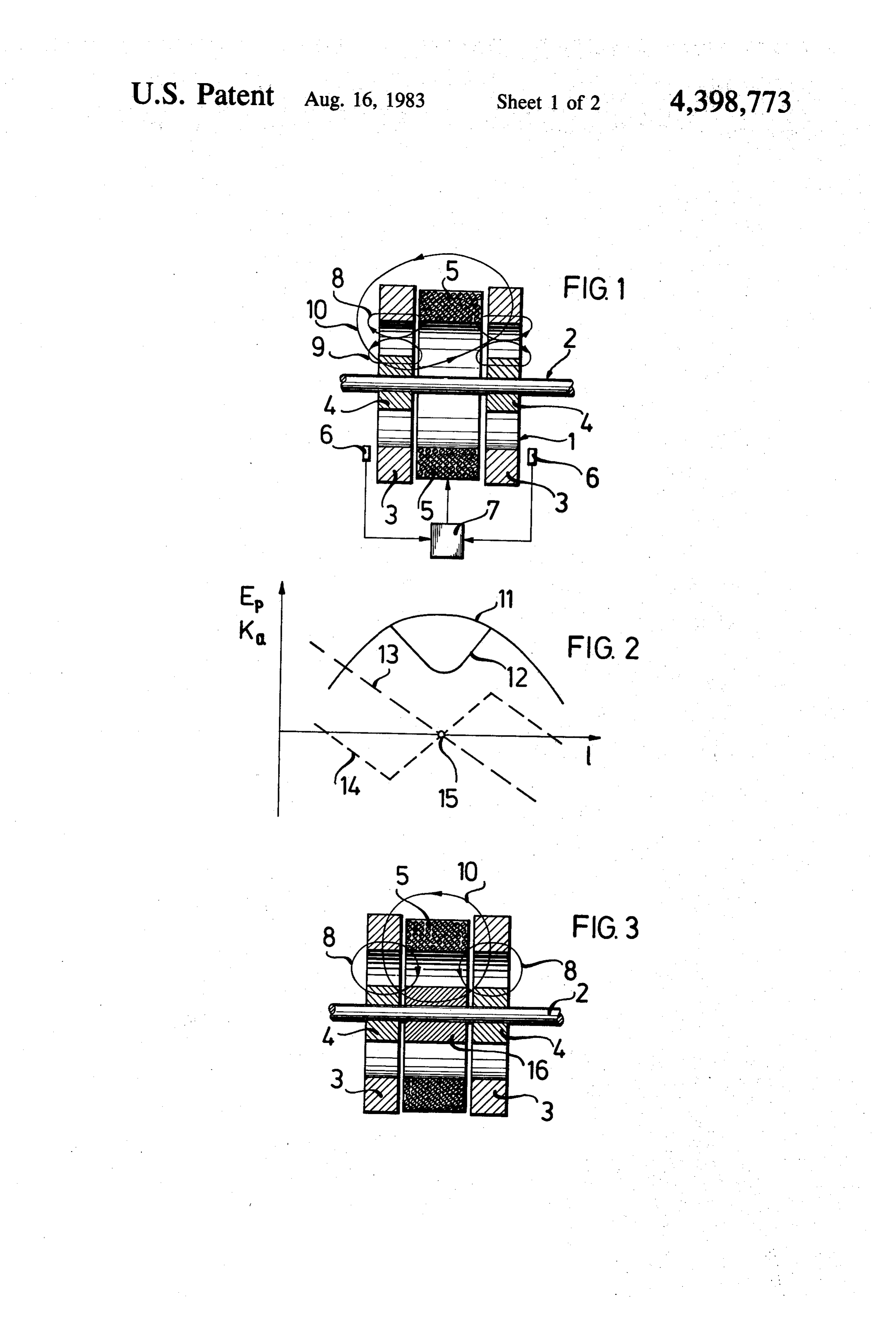
disposed in the tube. FIG. 2 is a graph plotting the potential energy and Obviously, such bearing systems interfere with the magnetic force generated in the axial direction along flow parameters, are subjected to wear and otherwise the ordinate against the axial displacement of the rotor have disadvantages resulting from contamination or the 50 along the abscissa;
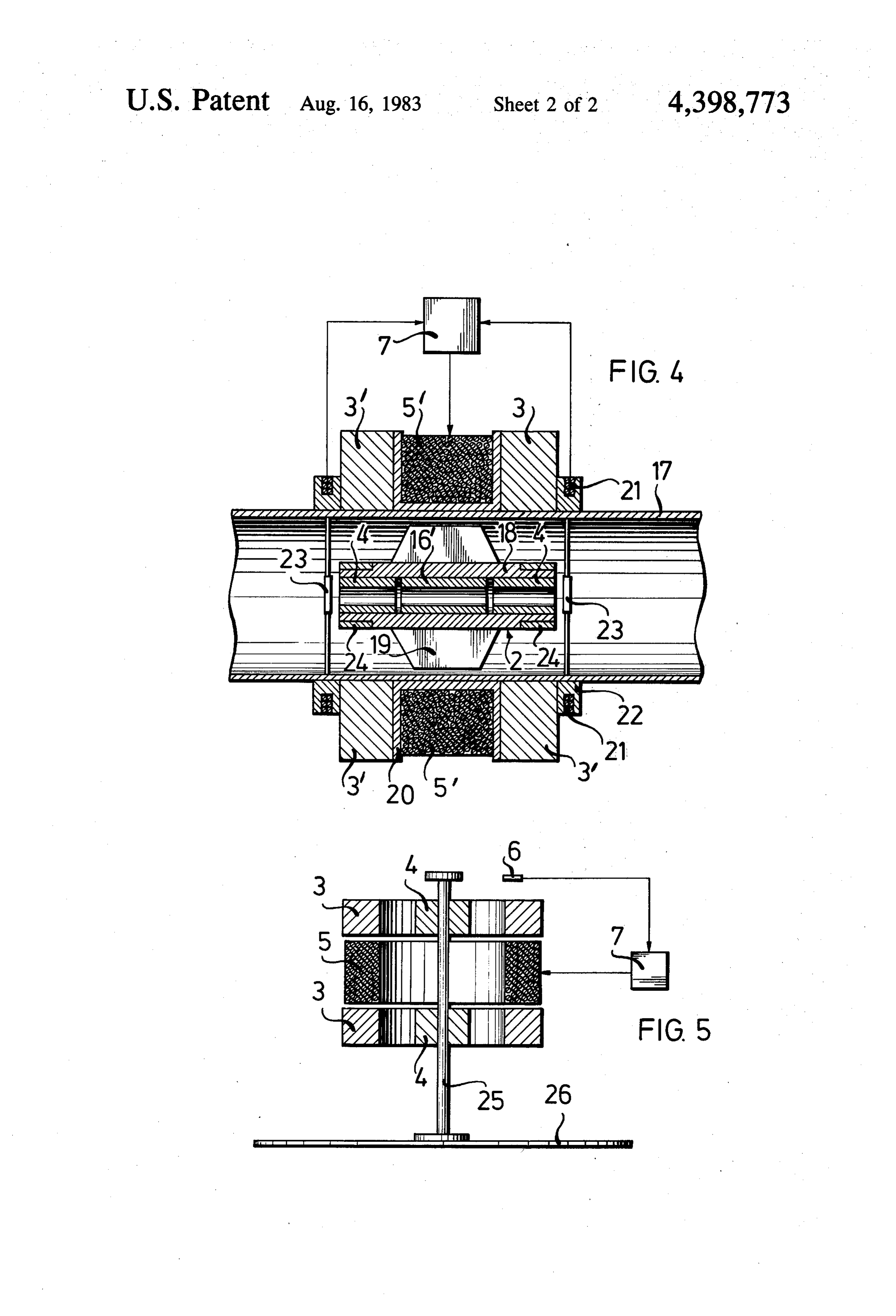
like of moving parts. When the measured fluid is a cor FIG. 3 is a view similar to FIG. 1 illustrating another rosive medium, moreover, the bearing parts must be embodiment of the invention;
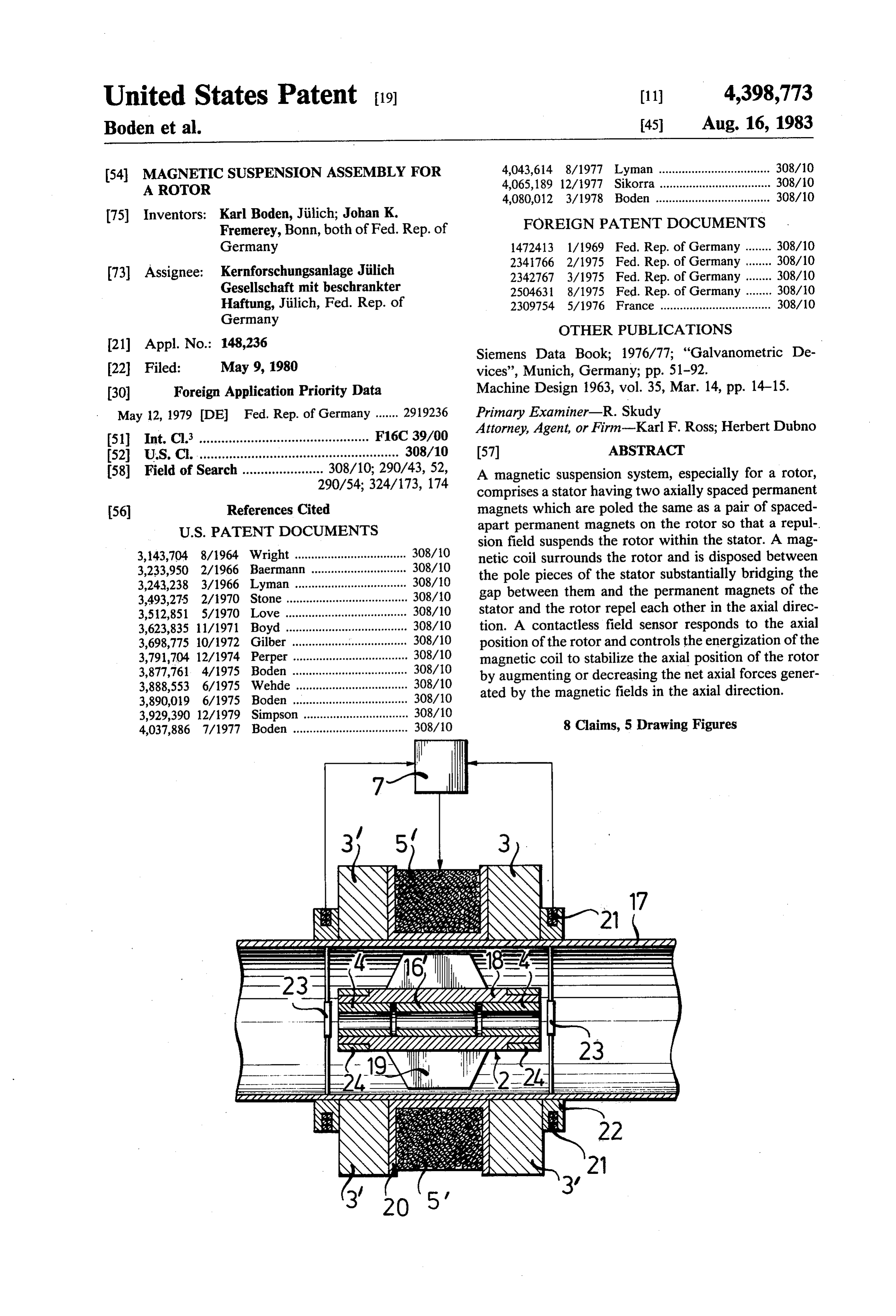
formed from a corrosion-resistant system at relatively FIG. 4 is an axial cross-section view, also in diagram high cost. matic form, showing a flow-monitoring device embody With the system described above in accordance with 55 ing the principles of the present invention; and the present invention, however, the coil, the stator mag FIG. 5 is an axial cross-sectional view in diagram nets and the pickup can all be located externally of the matic form showing the principles of the present inven tube and completely out of the path of the measured tion as applied to the elastic suspension of a rotor for an fluid. Nevertheless the system provides both passive electric meter. w radial stabilization and active axial stabilization which is 60
SPECIFC DESCRIPTION
effective independently of flow rate fluctuations since all axial forces applied by the gas to the rotor can be The magnetic suspension system shown diagrammati balanced by the magnetic field contribution of the coil. cally in FIG. 1 comprises a stationary stator 1 in which There is absolutely no bearing friction so that the mea a rotor 2 is suspended for coaxial rotation by magnetic surement precision is high, wear is eliminated and con 65 forces in a contactless manner. tamination of bearing surfaces completely excluded. The stator 1 is provided with two circular permanent Furthermore, since the tubular housing can be com magnets 3 which are coaxial with each other and are pletely sealed, the system may be used for measuring spaced by an axial distance bridged completely or sub
Page 6
stantially completely by a coil 5 coaxial with the rotor the magneto resistors 6 into voltages which are ampli and with these permanent magnets. fied and processed in an electronic phase-shifting net Two annular or sleeve-like permanent magnets 4 are work to control the power supply to the coil 5 and mounted on the rotor 2 at the same distance, i.e. each is determine the direction of polarity of this current and juxtaposed with one of the permanent magnets 3. hence the current flow, direction to the coil depending The rotor 2 is shown as a simple shaft for conve upon the direction in which the rotor displacement nience, although it will be generally coupled to a work occurs. The magnetic field contribution 10 of the coil ing mechanism as will be described in connection with increases with increasing displacement. FIGS. 4 and 5, or of any of the devices previously The phase-shifting network 7 results in a delay in the described. In addition, the coil 5 may be mounted upon O response of the opposing force to an axial displacement a coil carrier surrounding the shaft 2 or simply sepa of the rotor so that the restoring force also functions as rated therefrom by an air space.
The permanent magnets are magnetized so that in the arotor damping force preventing untoward oscillation of the in the axial direction.
axial direction the field component 8 of the permanent magnets 3 and the field component 9 of the permanent 15 and withenergy
The of the coil 5 depending upon direction magnets 4 are oppositely oriented so that the permanent axial position of thecurrent variable amplitude thus maintains the magnets of the rotor are thus magnetized in mutual ance to either side of the set pointa predetermined rotor within position 15.
toler repulsion and the permanent magnets of the stator have FIG. 3 shows an embodiment of the invention in corresponding parts magnetized in mutual repulsion.
Between the paired permanent magnets 3, 4 at each 20 shapedthe which rotor 2 is provided with an annular or sleeve end, the field components 8, 9 run axially outwardly for path of the coil 5 andbody ferromagnetic 16 which regulates the field strengthens the field generated each pair.
With energization of the magnetic coil 5, a controlled thereby. For the sake of simplicity in FIG. 3, the field magnetic field is superimposed upon the passive fields lines of permanent magnets 4 have not been shown. FIG. 4 shows a turbine-type flow meter which com of the four permanent magnets, the active field 10 add 25 prises a tubular housing 17 in which the rotor 2", pro ing to the coaxial field components 9 of the rotor or vided with vanes 19 is disposed for rotation in a contact subtracting therefrom. less and coaxial manner. The rotor and housing are In FIG. 1, for example, the field component contrib uted by the coil 5 adds to the field component 9 of the pulseprovided with a contactless rotation counter, e.g. a left magnet 4 and subtracts from the field component 30 former on the rotor and an inductive pulse detec from the right electromagnet. Obviously a reversal of tor on the housing, which have not been shown and the current flow through the coil 5 superimpose the which directly indicate the volume rate of low and field component 10 on the passive fields in the opposite velocity of the medium traversing the tubular housing direction. 17. The tubular housing 17 can be provided at its ends According to the invention, means is provided for the 35 with conventional flanges or connectors for placing the contactless sensing of the position of the rotor 2 and flow meter in any desired pipeline. controlling the current through the coil 5 to regulate The tubular housing 17 is composed of a nonmagnetic the superimposed field 10 as a function of this measure material with low electrical conductivity, e.g. glass, ment. which is also resistant to attack by the metered fluid and Contactless position detection can utilize any type of 40 which hermetically seals the flow passage from the transducer, e.g. an inductive, galvanomagnetic, capaci environment. No leakage can occur through any fittings tive or optic sensor. In FIG. 1 the sensor shown sche in the wall of the tube since none are provided. matically as two field plates (magneto resistors) are The rotor 2" comprises a hollow shaft 18 which is provided to respond to the change in magnetic fields formed with the vanes 19 and which is thus rotated as associated with movement of the rotor, straddle the 45 the liquid or gas flows past the rotor, the vanes being stator and provide their inputs to a control circuit 7 canted to the direction of flow. In the hollow shaft 18 varying the current flow in direction in the coil 5 (see there is provided centrally a ferromagnetic sleeve 16 Galvanomagnetic Devices, op cit.). FIG. 2 shows the and at each end a respective permanent magnet sleeve curve 11 of the potential energy E of the rotor as a 4'. The sleeves 4 and 16 are the functional equivalent to function of the axial displacement 1 of the rotor with 50 the permanent magnets 4 and field-concentrating sleeve respect to its original or set point position. This poten 16 previously described. A slight air gap is maintained tial energy drops from its maximum value at the set between each of the permanent magnets 4 and the point position with movement to either side so that the ferromagnetic sleeve 16" or the space between them is axial force Ka which results from the effect of the per filled with an electrical insulator. manent magnets corresponds to the curve 13, i.e. in 55 On the exterior of the tube 17, there are provided two creases with increasing distance from the set point 15, circular permanent magnets 3' between which the elec thereby accelerating the displacement of the rotor. trically energizable coil 5 is mounted, the coil being When, however, the magnetic coil 5 is energized as a provided with a coil carrier or coil former 20. function of the axial displacement, the potential energy The permanent magnets 3' and the coil 5' are the follows the curve 12, i.e. with increasing displacement 60 functional equivalents of the permanent magnets 3 and from the set point position, the potential energy first coil 5 previously described.
rises and then falls. The permanent magnets 3' are here juxtaposed with Curve 14, associated with the use of the coil 5, shows the permanent magnets 4 of the rotor 2' while the coil that the axial force inversely tends to draw the rotor 2 5' surrounds the ferromagnetic sleeve 16'. back to its zero position until the maximum potential 65 The permanent magnets are composed of conven energy peaks are reached. tional high coercive force materials such as barium, This control circuit 7 converts axial displacement of ferrite, samarium cobalt. magnetic materials and the the rotor from the proportional change in resistance of magnetic fields of the permanent magnets correspond to
Page 7
those described in FIG. 1. The device, operates however housing and responsive to movement of said metal as described in connection with FIG. 3. rings.
To provide a magnetic force balance for the rotor to 3. A magnetic suspension system comprising: oppose the force tending to drive the rotor in the direc a stator formed with two stator permanent magnets tion of flow of the liquid orgaseous medium, the axial spaced apart along an axis and an annular coil dis displacement of the rotor 2 is measured and the electri posed between said stator permanent magnets and cal current flow to the coil 5 is controlled accordingly. substantially completely bridging the gap between For this purpose, each end of the rotor 2" is provided them;
with a metal ring 24, e.g. of aluminum while the housing 10 a rotor surrounded by said stator permanent magnets 17 is formed with a pair of coil carriers 22 receiving and said coil and rotatable relative to said stator about respective sensing coils 21. said axis and out of contact with said stator, said rotor Upon axial displacement of the rotor 2, an inductive being provided with two rotor permanent magnets field change is detected by the coils 21 and is applied to axially spaced corresponding to the spacing between the control circuit 7. Obviously other contactless mea 15 the stator permanent magnets and each respectively suring devices such as galvanomagnetic capacitive or paired with a stator permanent magnet and poled in optical devices can be used. Particular mention should mutual repulsion, the stator permanent magnets being be made of the field plates similar to those of FIGS. 1 in mutual axial magnetic repulsion, and the rotor and 5 or Hall-effect generators. permanent magnets being magnetically poled in axial In the manner previously described, circuit 7 controls 20 repulsion;
the current traversing the coil 5' to balance magneti detection means for the contactless detection of axial cally the axial force tending to displace the rotor in the shifting of said rotor relative to said stator; direction of fluid flow. circuit means responsive to said detecting means for To draw off radial oscillation energy from the rotor energizing said coil to superimpose an active mag 2", damping elements 23 in the form of electrically con 25 netic field on the fields of said permanent magnets ductive metal plates or disks can be mounted ahead of and restore said rotor to a set point position by mag each of the rotor 2", the damping elements 23 being netic axial force, said stator being formed with a shown to be mounted by arms on the inner wall of the tubular housing and the stator permanent magnets tube 17. being mounted on said housing along the exterior FIG. 5 shows an embodiment which is functionally 30 thereof, said coil surrounding said housing, said rotor equivalent to that of FIG. 1 but is applied to the journal being formed with vanes whereby rotation of the ling of a vertical or erect shaft in an electrical meter, the rotor signals fluid flow parameters of a fluid travers disk 26 of which may be the conventional induction ing said housing, a respective metal ring being pro disk. This system can be used in any Watt-hour meter. vided at each end of said rotor and said detecting We claim: 35 means including a pair of coils mounted on said hous 1. A magnetic suspension system comprising: ing and responsive to movement of said metal rings, a stator formed with two stator permanent magnets said rotor being formed with a hollow shaft and said spaced apart along an axis and an annular coil dis rotor permanent magnets being received in said shaft; posed between said stator permanent magnets and and substantially completely bridging the gap between 40 a ferromagnetic sleeve received in said shaft and spaced them; from the rotor permanent magnets. a rotor surrounded by said stator permanent magnets 4. The system defined in claim 3 wherein the rotor and said coil and rotatable relative to said stator about permanent magnets are formed as sleeves. said axis and out of contact with said stator, said rotor being provided with two rotor permanent magnets 45 a stator formed suspension 5. A magnetic with two system comprising:
stator permanent magnets axially spaced corresponding to the spacing between spaced apart along an axis and an annular coil dis the stator permanent magnets and each respectively posed between said stator permanent magnets and paired with a stator permanent magnet and poled in substantially completely bridging the gap between mutual repulsion, the stator permanent magnets being them;
in mutual axial magnetic repulsion, and the rotor 50 a rotor surrounded by said stator permanent magnets permanent magnets being magnetically poled in axial repulsion; and said coil and rotatable relative to said stator about detecting means for the contactless detection of axial said axis and out of contact with said stator, said rotor shifting of said rotor relative to said stator; being provided with two rotor permanent magnets circuit means responsive to said detecting means for 55 axially the spaced corresponding to the spacing between stator permanent magnets and each respectively energizing said coil to superimpose an active mag netic field on the fields of said permanent magnets paired with a stator permanent magnet and poled in and restore said rotor to a set point position by mag mutual repulsion, the stator permanent magnets being netic axial force, said stator being formed with a in mutual axial magnetic repulsion, and the rotor tubular housing and the stator permanent magnets 60 permanent magnets being magnetically poled in axial being mounted on said housing along the exterior repulsion;
thereof, said coil surrounding said housing, said rotor detection means for the contactless detection of axial being formed with vanes whereby rotation of the shifting of said rotor relative to said stator; rotor signals fluid flow parameters of a fluid travers circuit means responsive to said detecting means for ing said housing." 65 energizing said coil to superimpose an active mag 2. The system defined in claim 1 wherein a respective netic field on the fields of said permanent magnets metal ring is provided at each end of said rotor and said and restore said rotor to a set point position by mag detecting means includes a pair of coils mounted on said netic axial force.
Page 8
6. The system defined in clam 1, further comprising a ends of said rotor and composed of a material having a o body disposed between said rotor permaferromagnetic high electrical conductivity. 8. y disp p 8. The system defined in claim 1 or claim 2 whereinnent magnets. said rotor is formed with an erect shaft of an electric 7. The system defined in claim 1, further comprising 5 power meter.
a damping element juxtaposed with at least one of the k if k k
Provenance
- Collection
- Cited prior art
- Original PDF
- patentimages.storage.googleapis.com →
- Filed
- 1980-05-09
- Pages
- 8
- Method
- pdftotext (the PDF's own text layer) + pdftoppm 300dpi page scans
- Source
- Google Patents bibliographic record
- Granted
- 1983-08-16
- Inventors
- Karl Boden; Johan K. Fremerey; Kernforschungsanlage Juelich GmbH
- Transcribed from
- patentimages.storage.googleapis.com →