patent · US5801470
Rotors with retaining cylinders and reduced harmonic field effect losses
1 September 1998
Page 1 — bibliographic record
United States Patent (19) 11 Patent Number: 5,801,470 Johnson et al. 45) Date of Patent: Sep. 1, 1998 54) ROTORS WITH RETAINING CYLINDERS 5,038,065 8/1991 Matsubayashi et al................. 310,162 AND REDUCED HARMONC FELD EFFECT 5,091,668 2/1992 Cuenot et al. .......................... 310,156 LOSSES 5,485,045 1/1996 Canders et al. . ... 310,156 5,528,095 6/1996 Strobl ...................................... 310,56 75 Inventors: Roger Neal Johnson, Hagaman;
Gerald Burt Kliman. Niskayuna, both FOREIGN PATENT DOCUMENTS of N.Y.; Yuefeng Liao, Brookfield, 1632O8-C2 8, 1982
Wis.; Wen Liang Soong, Schenectady, 3-195338 A 31991
N.Y. 6-78.481. A 3/1994
(73) Assignee: General Electric Company,
Schenectady, N.Y. Primary Examiner-Steven L. Stephan
Assistant Examiner-Elvin G. Enad 21 Appl. No.: 770,215 Attorney, Agent, or Firm-Ann M. Agosti; Marvin Snyder 22 Filed: Dec. 19, 1996 57 ABSTRACT (51) Int. Cl. ... HO2K 21/12 A rotor includes a shaft; a permanent magnet layer; and a 52 U.S. Cl. ......................... 310/156; 310,254; 310/261; retainer comprising a conductive, low magnetic permeabil 310/271 ity material bound to the rotor shaft. The permanent magnet 58) Field of Search ..................................... 310/156.254, layer is semi-restricted between the shaft and the retainer. In 310/261,271 one embodiment, the magnet layer includes a molded ring magnet. In another embodiment, the magnet layer includes (56) References Cited a plurality of magnet segments which can be situated on the rotor in rotor pockets or in a rotor cage. The bond between
3,593,049 7/1971 Dittrich ..................................... 31040 support elements. A high conductivity material can be situ 3,727.302 4/1973 Phelon ...................................... 29,596 ated over the retainer with the combination of the retainer 3,789.250 1/1974 Macoit et al. 310,154 and the high conductivity material having a resistivity high 4012,651 3/1977 Burson ...... 31OWS3 enough to minimize space harmonic losses and low enough 4,146,809 3/1979 Rielly .................................. 310261 to minimize time harmonic losses. The high conductivity
waa material can also be applied to induction rotors for excluding
4,636,107 1/1987 Casler et al... 403/405 g F.quency components while permitting penetration of 4,729,160 3/1988 Brown ........... ... 29/598 quency torque producing fields. 4,916,344 4/1990 Hammer et al. .. ... 30/54 4,953.284 9/1990 Hammer et al. .......................... 29,296 14 Claims, 6 Drawing Sheets
SSSSSSSSSSSSSSSSSSSSSSaaSaaSNNSSNS
NZZZZZZZZZZZZZZZZZZZYZZZZZZZZZZY NS
N ZZZZZZZZZZZZZZZZZZZZZZZZZZZZNS
NYaYaNYNNSSSSSSSSSSSSSSSNSSYNYNY
NSYNNNNNNNyay
Page 2
Drawing sheet — no readable text.
Page 3
Drawing sheet — no readable text.
Page 4
Drawing sheet — no readable text.
Page 5
Drawing sheet — no readable text.
Page 6
Drawing sheet — no readable text.
Page 7
Drawing sheet — no readable text.
Page 8
ROTORS WITH RETAINING CYLINDERS inside-out motor with no preload. In conventional systems, AND REDUCED HARMONIC FELD EFFECT sufficient radial preload is applied to provide a heavy inter LOSSES ference fit of about 1 mil per inch of diameter between the retainer and a rotor shaft to ensure that nothing moves within
The invention was made with Government support under 5 the rotor. In the present invention, a light interference fit contract number 70NANB5H1119 awarded by the National (preferably less than or equal about 0.5 mils per inch of Institute of Standards and Technology. diameter) is used between the retainer and the magnets, and the magnets can expand several mils or more as the speed of
BACKGROUND OF THE INVENTION the shaft is raised from standstill to full speed. To maintain 10 a balanced rotor, the magnets must stay in contact with the
In conventional high speed permanent magnetic (PM) retainer during speed changes and not shift. Cylindrically motors, magnet retention is achieved by shrinking or press shaped permanent magnets either whole or in segments can ing a high strength shell over the magnets. The shell must be held over a steel shaft by a metal alloy retaining cylinder have low permeability (preferably 1.00) to avoid short in a less restrictive manner than conventional magnets are circuiting the magnet flux, have low electrical conductivity 15 held. The magnets expand or are otherwise forced outwards to minimize space and time harmonic losses, and comprise during rotor rotation to follow the expansion of the retainer. a thin layer of material having sufficient strength to provide The present invention thereby eliminates the need for a tight for magnet retention. The thickness of the shell preferably interference fit of a retainer sleeve and a portion of the close ranges from about 0.01 inches to about 0.12 inches. Con tolerance radial dimensions that are associated with the tight ventional shell materials are austenitic stainless steel or a interference fit assembly process. The present invention heat-treatable alloy containing primarily nickel, chromium, additionally enables the use of molded magnets which and iron. The shell must be highly stressed to avoid sepa cannot tolerate the elevated temperatures required for large ration of the magnets from the shaft at high rotor operation interference shrink fits.
speeds. Thus, a tight interference fit must be used which In another embodiment of the present invention, a thin requires large temperature differentials or force during 25 layer assembly, and tight tolerances, for motors capable of oper of a of high conductivity material is applied on the surface rotor to exclude high frequency components while ating at very high speeds. The materials that can be used for permitting full the permanent magnets are limited to those materials that production. penetration of low frequency fields for torque can withstand the high temperatures and stresses required for fabrication. 30 BRIEF DESCRIPTION OF THE DRAWINGS An alternative embodiment is to turn the motor "inside out" so that the stationary windings occupy the center The features of the invention believed to be novel are set position and the rotor yoke turns on the outside. In this forth with particularity in the appended claims. The inven embodiment, the magnets are held against the centrifugal tion itself, however, both as to organization and method of forces by the yoke itself so that only some projections and 35 operation, together with further objects and advantages adhesive are needed to position and secure the magnets. No thereof, may best be understood by reference to the follow retainer is needed in the magnetic circuit to increase the gap. ing description taken in conjunction with the accompanying Such inside-out motors typically require much more space drawings, where like numerals represent like components, in than conventional motors and have correspondingly which:
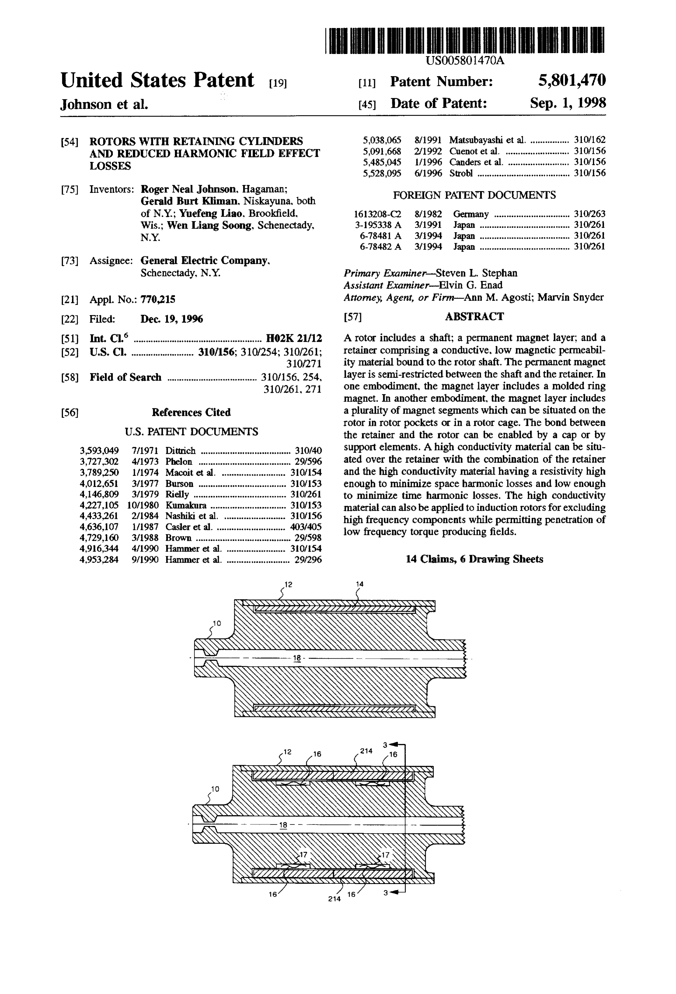
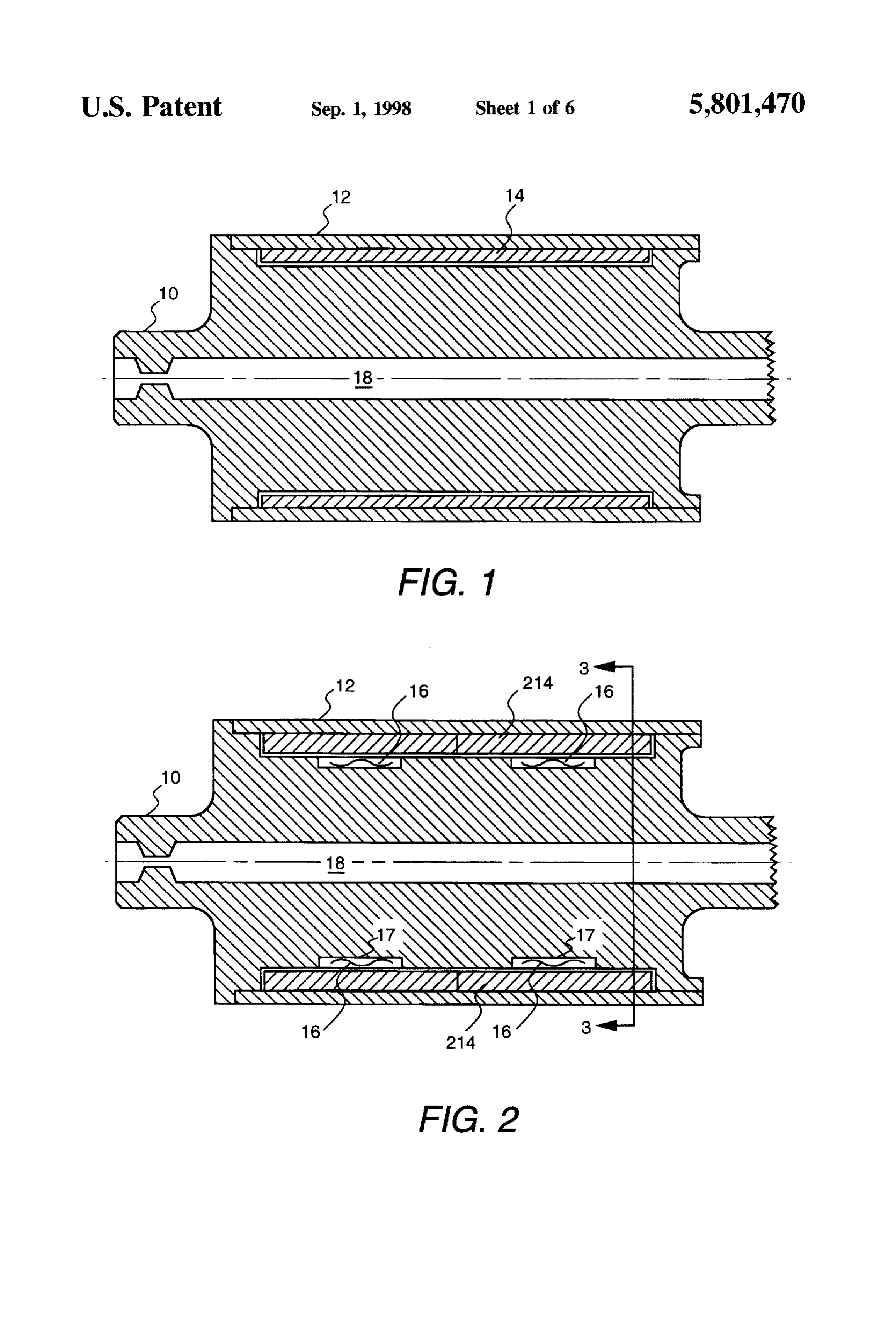
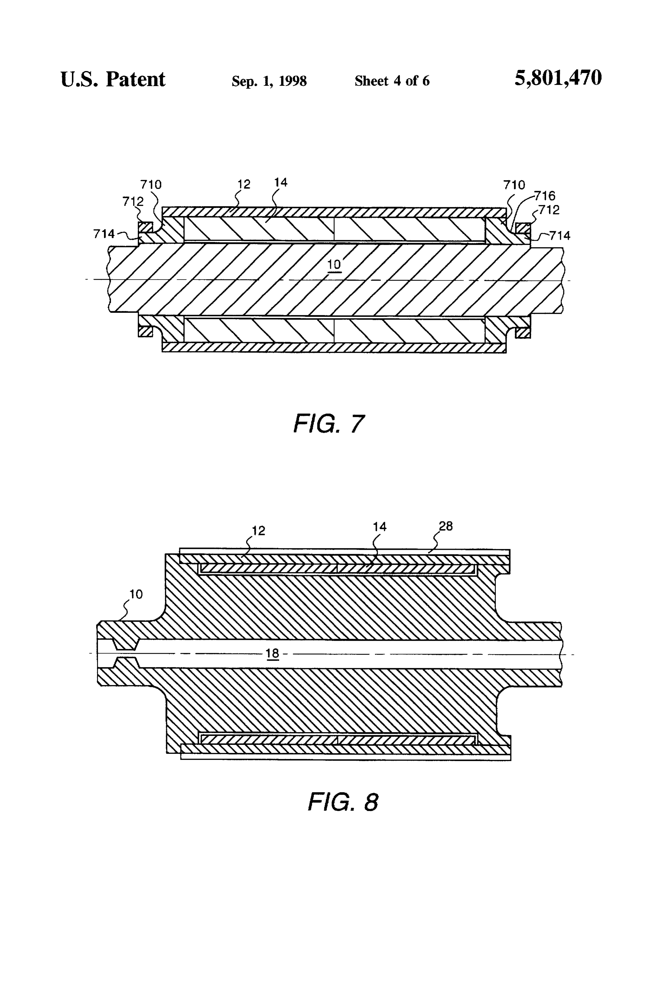
increased stresses thereon. FIG. 1 is a sectional side view of one embodiment of a Harmonic fields resulting from inverter chopping (or rotor of the present invention comprising a shaft, a perma pulse width modulation) and spatial variation (slotting) of nent magnet layer, and a retainer.
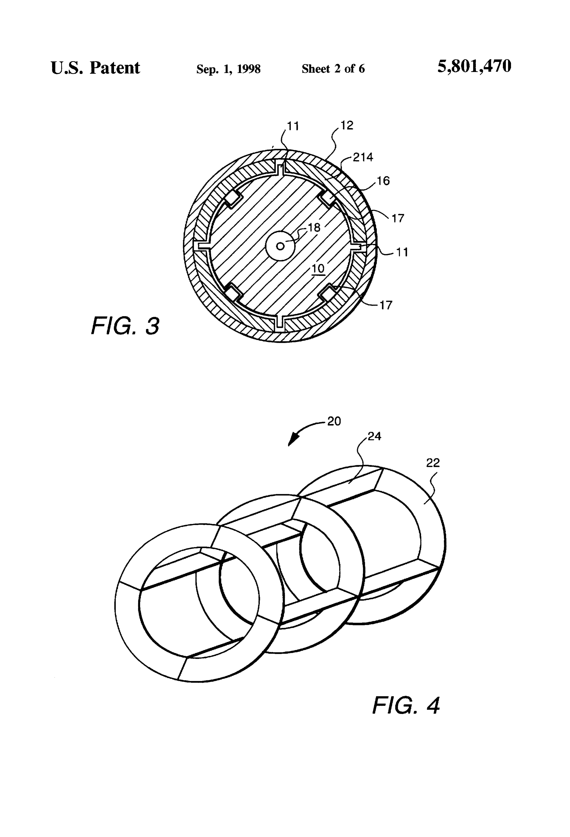
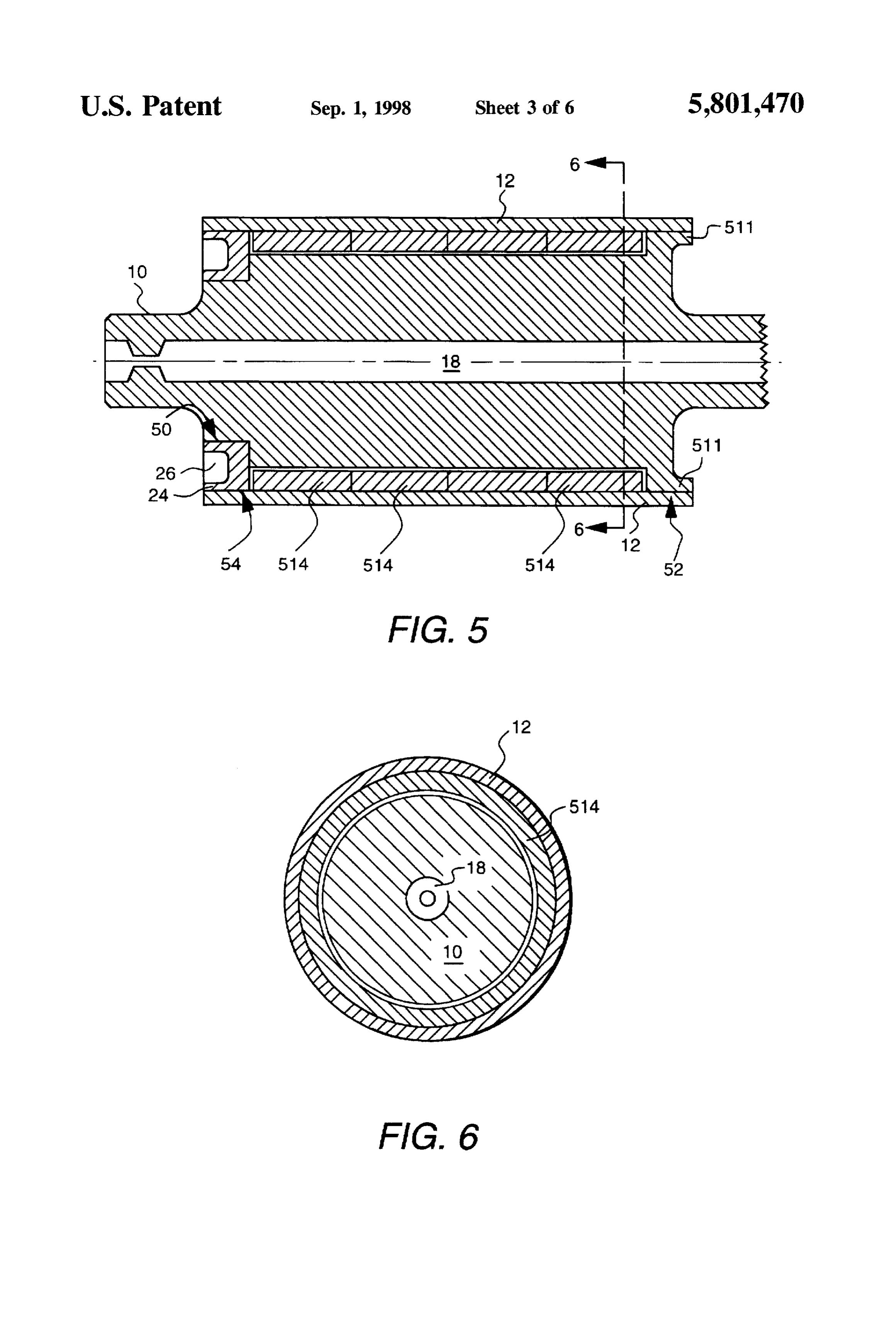
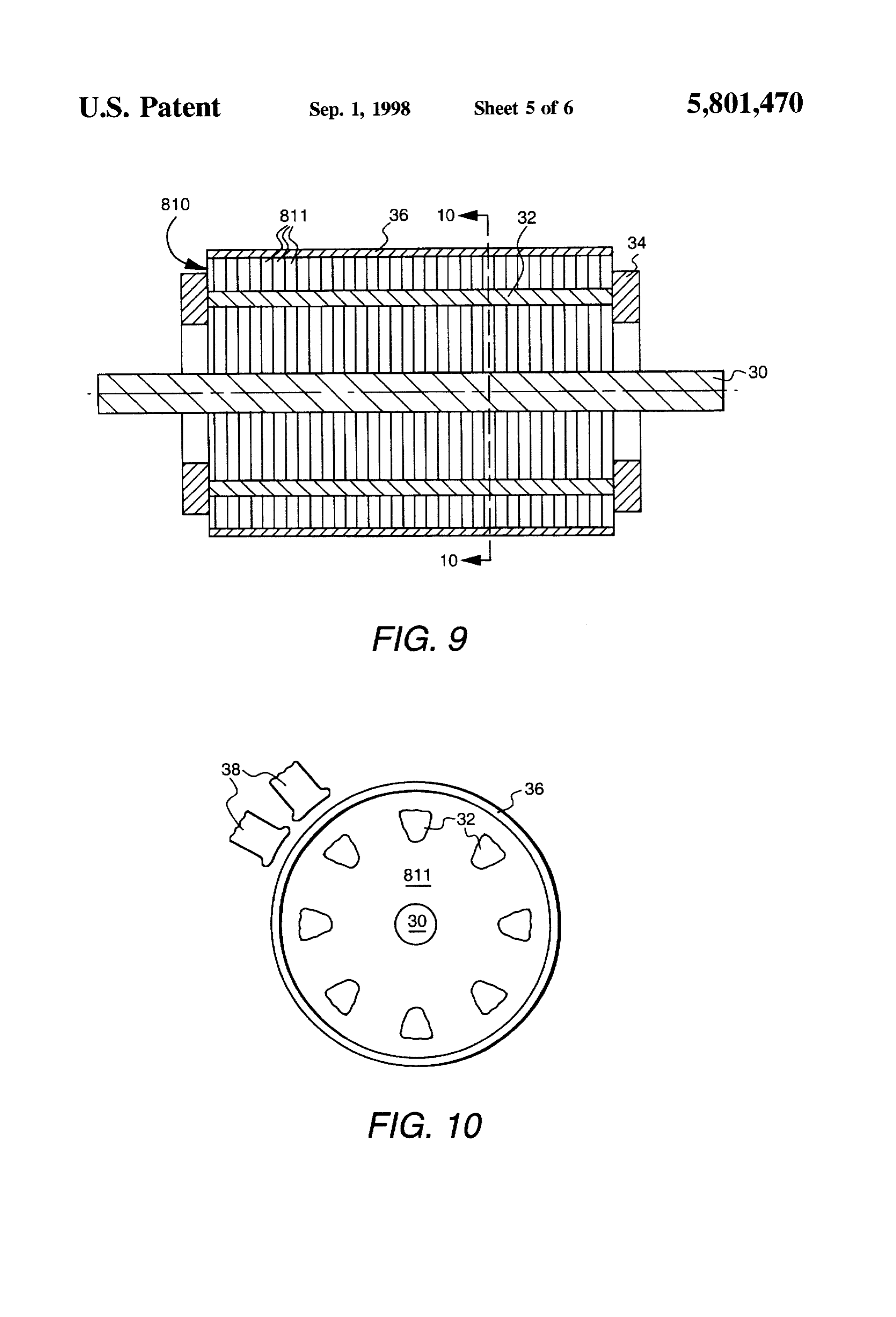
stator fields often create excessive losses in magnet FIG. 2 is a view similar to that of FIG. 1, further showing retainers, magnets, and rotor cores of permanent magnet springs for positioning permanent magnets. motors. Analogous losses occur in induction motors from 45 FIG. 3 is a view along line 3-3 of FIG. 2. induced surface (pole face losses) and circulating currents FIG. 4 is a perspective view of a cage for holding rotor (eddy current losses) in the rotor bars. These losses represent material of the present invention. a substantial portion of the stray load losses present in fixed FIG. 5 is a view similar to that of FIG. 1, further showing frequency induction motors. a weld cap.
Thin copper layers are sometimes used in conjunction 50 with high permeability layers to exclude high frequency FIG. 6 is a view along line 6-6 of FIG. 5. fields from shielded rooms. Copper has been explosively FIG. 7 is a view similar to that of FIG. 1, further showing bonded to solid stainless steel slot wedges in a high speed, Supports and rings.
wound field generator to shield the slot wedges from space FIG. 8 is a view similar to that of FIG. 1, further showing harmonics. These principles have not been applied to per 55 a layer of high conductivity material overlying the retainer, manent magnet or induction motors. FIG. 9 is a sectional side view of another embodiment of
SUMMARY OF THE INVENTION
a rotor of the present invention including a layer of high conductivity material overlying induction motor rotor lami
It would be desirable to have an efficient method for nations.
fabricating permanent magnetic rotors for high speed inte FIG. 10 is view along line 10-10 of FIG. 9. gral horsepower motors. FIG. 11 is a view similar to that of FIG.9, further showing It would also be desirable to reduce losses in induction an oxide layer between the rotor laminations and the layer of and permanent magnet motors that result from harmonic high conductivity.
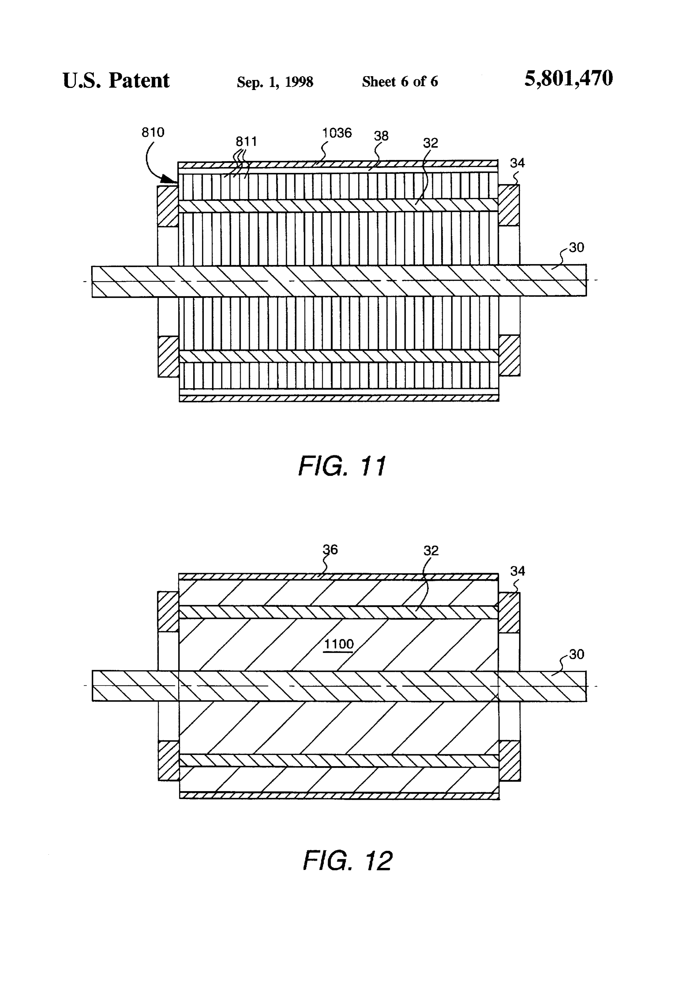
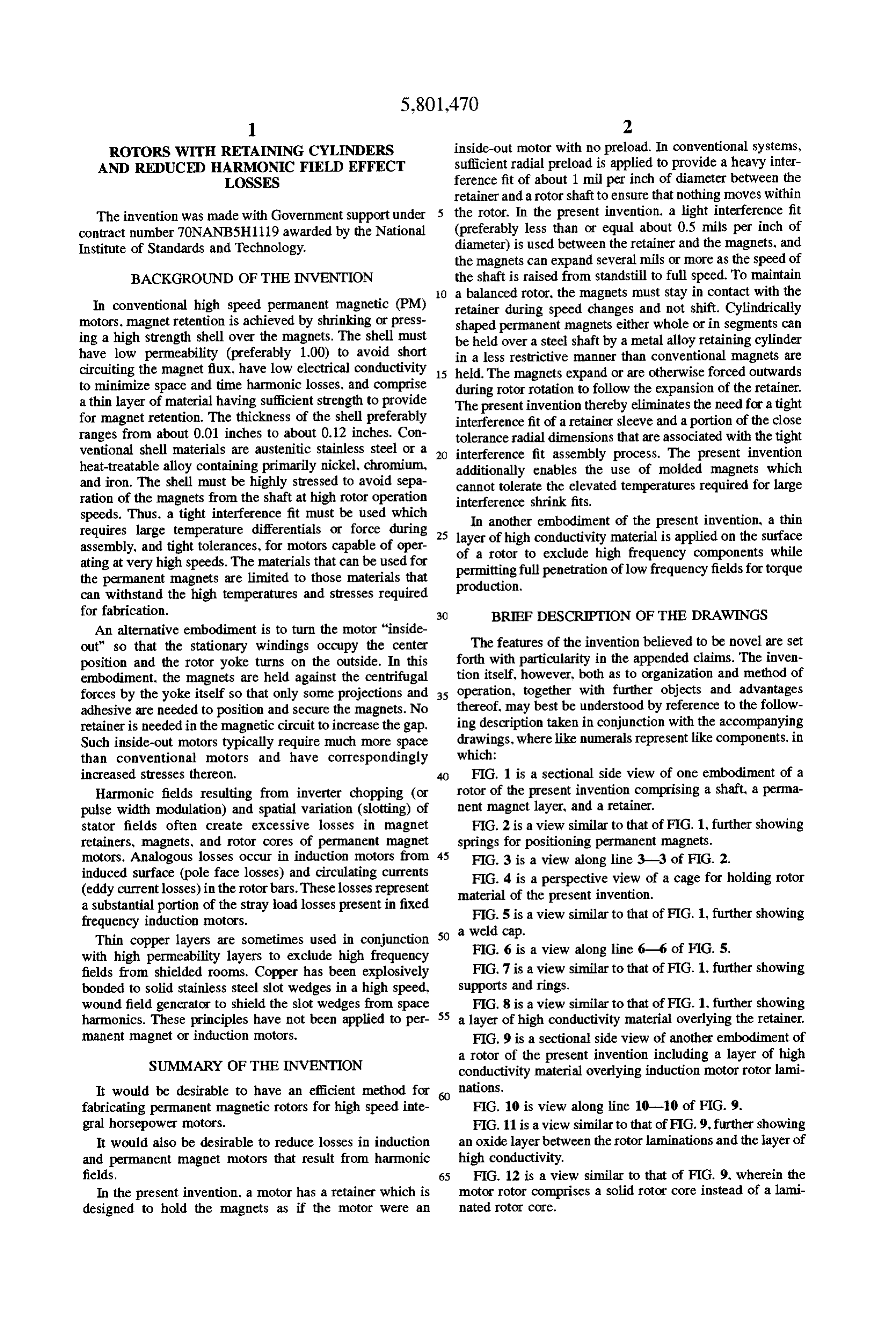
fields. 65 FIG. 12 is a view similar to that of FIG. 9, wherein the In the present invention, a motor has a retainer which is motor rotor comprises a solid rotor core instead of a lami designed to hold the magnets as if the motor were an nated rotor core.
Page 9
DETALED DESCRIPTION OF A PREFERRED The fit between the magnets and the pockets can be EMBODIMENT OF THE INVENTION relatively loose, on the order of a few mils. The leaf springs FIG. 1 is a sectional side view of one embodiment of a hold the magnets in contact with the retainer as they move rotor of the present invention comprising a shaft 10, a radially to follow the expansion and contraction of the permanent magnet layer 14, and a retainer 12. The shaft 5 retainer as the rotor speed varies.
comprises a high permeability magnetic metal such as steel FIG. 4 is a perspective view of a cage 20 for holding rotor having an optional hollow core 18 to increase rotational material of the present invention. This embodiment is simi critical speed and/or permit through flow of a fluid. The lar to that of FIG. 2 except that instead of creating protru retainer often comprises a conductive material having high sions or machining pockets in the rotor, a separate structure strength and low magnetic permeability, such as O provided. This structure may comprise, for example, a INCONELM 718 (a trademark of Inco International, Inc. of isstainless
Huntington, W.V., for a corrosion-resistant alloy containing struts 24.steel
cage fabricated with intersecting rings 22 and an alternate embodiment, the structure may primarily nickel, chromium, and iron). The retainer can comprise a thin sheet, at the inner diameter of the magnets, alternatively comprise a composite of non-conductive mate rials such as KEWLARTM aromatic polyamide fibers 5 and, configured with protrusions that act to situate the magnets (KEVLAR is a trademark of E. I. duPont de Nemours & in the other direction, springs to lightly preload them Co.). Retainer 12 provides the necessary support for the against the restraint.
magnet layer 14 to resist centrifugal forces. In one embodi FIG. 5 is a sectional side view of another embodiment of ment the retainer is cylindrical and has a thickness ranging a rotor of the present invention, and FIG. 6 is a view along from about 0.04 inches to about 0.12 inches. line 6-6 of FIG. 5. To install cylindrical magnets 514 which In the embodiment of FIG. 1, the magnet layer comprises are one piece rings, an end of the rotor must be open to a continuous ring magnet that is fabricated and mated to the permit the magnets to be installed axially. In one retainer with a light interference fit. In one embodiment the embodiment, the other end of the rotor includes a radial magnet layer material comprises a NdeB bonded magnet projection 511.
having a thickness ranging from about /s of an inch to about 25 Prior to assembly, the retainer and shaft are heat-treated % of an inch. The magnet is semi-restricted (not rigidly and finish-machined. To achieve a light interference fit, the attached to the shaft or core) and thus, in one embodiment, magnets and retainer cylinder are finished on the outer will expand as speed is increased to stay in contact with the diameter and inner diameter surfaces, respectively. The retainer because its stiffness is less than the retainerstiffness. outer diameter of the shaft beneath the magnets can be Thus, close control of the inside radius dimension of the 30 approximately 0.01 inches less than the magnet inner magnet layer and the outside radius of the adjacent shaft is diameter, thereby ensuring that a radial clearance exists. The not required. joints to be welded must have tight interference fits adjacent Furthermore, heating the retainer to approximately 1000 to the Welds to maintain diametrical contact of surfaces F. for assembly to achieve the required preload necessary to during operation and to minimize cyclic stresses on weld exceed centrifugal forces is avoided. Because such heat is 35 joints. The magnitude of cyclic or alternating stress has a not required, use of molded magnets with a polymer binder large effect upon fatigue life of metallic components. is feasible. The retainer can be pressed or shrunk onto a weld cap 24 The retainer can be welded to one or both ends of shaft 10. comprising steel, for example, and the retainer?weld cap Welding the ends of the retainer to the shaft forms an integral joint 54 can be welded with a minimal heat input process structure which will have a more predictable critical speed such as an electron beam or laser welding process. The than a tightly interference-fitted assembly. retainer temperature can be raised approximately 150° C. FIG. 2 is a sectional side view of another embodiment of above ambient and the magnets (in an unmagnetized state) a rotor of the present invention, and FIG. 3 is a view along inserted in retainer 12 to achieve a light interference fit. The line 3-3 of FIG. 2. The layer of permanent magnet material shaft 10 can be chilled with a liquid such as nitrogen (N). in this embodiment comprises segments 214 of permanent 45 for example, to approximately -100° C. and slid into the magnet material each having an outside radius substantially heated subassembly of the retainer and the magnets. The the same as the inside radius of the retainer. Magnet mate term "slid" is meant to encompass a situation either where rials generally do not have sufficient strength or are too the retainer and magnets are held in position while the shaft brittle to be self-supporting in high speed rotors. Retainer 12 is moved or where the shaft is held in position and the provides the necessary support for the magnet segments 214 50 retainer and magnets are moved. The two remaining joints to resist centrifugal forces. 50 and 52 can be welded again by an electron beam weld or Shallow pockets forming rotor protrusions 11 (shown in equivalent process which can achieve adequate penetration FIG. 3) can be machined in the shaft surface to situate the without over-heating the magnets. If an electron beam weld magnets. The protrusions can be used to separate individual is used, the beam must come in parallel to the shaft and the magnets so that the magnets do not contact each other and 55 shaft must be demagnetized to avoid defocusing and deflect are semi-restricted in that they can move slightly between ing the beam. It may be possible to use lasers for some of the protrusions, shaft surface and retainer. Springs 16 can be this welding.
used between shaft 10 and magnet segments 214 for pre In another embodiment, the retainer and magnets can be loading the magnet segments against the inside of the applied to the shaft prior to being attached to the weld cap. retainer. The springs are inserted into wells 17 in the shaft, After the weld cap is positioned, welds between the retainer and the magnets inserted over the springs and are tempo and weld cap, weld cap and shaft, and retainer and projection rarily restrained radially by rubber bands, for example, until are then provided.
the retainer is installed over the magnets. This embodiment FIG. 7 is a view similar to that of FIG. 1, further showing provides a dynamically balanced rotor assembly and is supports 710 and rings 712. Preferably, the supports com particularly useful for magnets such as sintered or heat 65 prise a non-magnetic material such as an INCONELTM metal processed magnets that do not change their shape as easily alloy. The retainer temperature can be raised and the mag as polymer bonded magnets. nets 14 can be inserted in retainer 12. Supports 710 can then
Page 10
S 6 be positioned, lightly shrunk, and welded in position by any to make the retainer or magnet resistivity as Small as convenient process. Increased welding flexibility is provided possible. Generally, reaction-limited losses are smaller than because the supports and retainers are not yet on the rotor resistance-limited losses for the same material. Induction shaft. Flexibility is further increased if the retainer and limitation situations result in the lowest losses but do not support materials are the same and the welds are therefore frequently occur.
between identical metals. Retainer losses due to inverter time harmonics are gen If the supports are a non-magnetic material, they will not erally reaction-limited. Losses due to space harmonics drain flux from the magnets as magnetic pieces would do. appear to be resistance-limited because of the fixing of the Therefore, less magnet material is required. The supports flux by the magnets and a somewhat lower effective fre can made with extensions 714 for ease of mounting to the quency. Therefore, it would be desirable to have resistivity shaft. Appropriate dimensions will depend on such factors as high enough to minimize space harmonic losses and low fits, materials, and temperatures in the design. Afillet 716 is enough to minimize time harmonic losses. useful so that stress concentration at the corner where an In the present invention, the high resistivity material is extension extends from a support is minimized. used for the retainer because of its mechanical requirements. The retainer, supports, and magnets are slid onto shaft 10 15 The retainer can then be provided with a thin coat of high with a light interference fit between the retainer and the conductivity material. The conductivity and thickness are shaft. In one embodiment, the clearance between the mag chosen such that it is reaction limiting for the high frequency nets and the shaft is about 5 mils. In this embodiment, the time harmonics and thin enough not to interfere with fun shaft can be more simply machined because no pockets or 20 damental flux penetration or yield excessive spatial har protrusions need be used. monic losses.
Shrink rings 712 can be applied to the support extensions In a design study, non-conducting magnets were sur 714. A tight interference fit can be used because the shrink rounded by a nonmagnetic retainer having a thickness of ring temperature can be made quite high without harming about 100 mils and a resistivity about 120 microhms the magnets or disturbing the welds of the supports to the centimeter (about seventy times the resistivity of copper). retainer. In one embodiment, the shrink rings comprise 25 The retainer was found to be reaction-limited to the time chromium-molybdenum steel or INCONELTM alloy, for harmonics but not to the space harmonics, and the time example. harmonics resulted in high losses. A layer of copper about FIG. 8 is a view similar to that of FIG. 1, further showing 1.3 mils thick is expected to result in reaction-limiting of a layer 28 of high conductivity material overlying retainer 30 about the same order as the retainer but with much lower 12. resistivity. A layer a few mils thick is expected to reduce the A surface magnet brushless DC motor typically comprises time harmonic losses considerably while not increasing the a slotted or salient pole stator with windings, a rotor includ space harmonic losses too much. A balance in the electro ing a solid core and shaft of high permeability magnetic steel magnetic design of such systems is necessary and can be (a conductor), and magnets surrounding the rotor core. 35 aided by computer simulations.
Harmonic fields resulting from slotting of the stator and Layer 28 can be shrunk on the retainer but is probably chopping of the power electronics induce losses in materials more conveniently and economically applied by electroplat of the rotor. The magnets themselves are often electrical ing. Because copper is a soft material, it will expand more conductors and therefore the site of losses due to space and than other metals under stress. Plating can bond copper to time harmonic fields. the substrate and prevent separation at high speeds. Other As discussed above, in many permanent magnet motors, examples of useful materials for layer 28 include silver and especially high speed motors, a retainer 12 of non-magnetic gold.
high strength material covers the magnets. The retainer is FIG. 9 is a sectional side view of another embodiment of often an electrical conductor and hence the site of eddy a rotor of the present invention including a layer of high current losses due to harmonic fields. The harmonic fields 45 conductivity material 36 overlying induction motor rotor have two sources. One source is a high frequency current 810 aminations 811 with rotor bars 32, and FIG. 10 is view ripple in the stator windings (not shown) due to the chopping along line 10-10 of FIG. 9.
or pulse width modulation operation of the power electronic The technique is useful in induction motors for reducing drivers. This source is higher in frequency than the funda the time harmonic induced losses in the rotor. The theory is mental or torque producing frequency. The second source is 50 contrary to the usual rule of carefully treating the surface so the spatial variation of the stator fields due to slotting or that there is no connection between rotor laminations. The salient poles in the stator. reasons for laminating induction motor rotors are generally The eddy current losses in the conducting regions affected to (1) assure flux penetration. (2) minimize rotor core losses, by the harmonic fields can be of a nature that is resistance and (3) minimize the "pole face" component of the stray limited, reaction-limited, or inductance-limited. In the situ 55 load losses from stator pole teeth 38. ation of a resistance limitation, the reaction fields resulting Because slip is on the order of 1% or less in a typical high from induced currents are negligible compared to the efficiency, high speed motor, the torque producing frequency imposed fields. Therefore, voltages will be induced in the is very low (under 10 hertz) in the rotor. Therefore. rotor conductors with the current limited only by the resistance of core losses can be kept low and flux penetration can be the medium. To compensate for this effect, the retainer or assured even if the laminations are not well isolated. Low magnet resistivity is selected to be as large as possible. order harmonics of the inverter may be present. However, a In the situation of reaction limitation, the fields produced thin copper layer can be more effective than a well-isolated by the eddy currents are comparable to the imposed fields, lamination stack at reducing time harmonic surface losses. and, in the ideal situation, exactly cancel them. Thus, as in For each particular situation, a computer simulation can be an ideal transformer, the currents in the retainer or magnet 65 used to evaluate the trade-off and design parameters. will equal the driving current in the stator (the ripple A further issue is the eddy currents in the bars which current). In this situation the method for reducing losses is would be shielded by the copper layer but unaffected by
Page 11
better laminations. Because there are no permanent magnets, 3. The rotor of claim 1, wherein the retainer has a rotor the induction motor harmonic fields are not embedded and projection at one end and a cap an another end, and wherein the copper layer may actually improve the efficiency of a the bond between the rotor shaft and the retainer comprises standard sixty hertz fixed frequency industrial induction a weld between the retainer and the projection of the rotor notor. shaft, a weld between the retainer and the cap, and a weld FIG. 11 is a view similar to that of FIG.9, further showing between the cap and the shaft.
an oxide layer 38 between the rotor laminations 811 and a 4. The rotor of claim 1, wherein the permanent magnet layer of high conductivity 1036. Oxide layer 38 permits the layer comprises a plurality of magnet segments on the rotor laminations to remain isolated. In one embodiment, layer of 10 shaft.
high conductivity 1036 is applied by a shrink fit process. 5. The rotor of claim 4, wherein the rotor shaft includes FIG. 12 is a view similar to that of FIG. 9, wherein the pockets and the plurality of magnet segments are situated in motor rotor 1100 comprises a solid rotor core instead of a respective pockets.
laminated rotor core. This embodiment would be useful if 6. The rotor of claim 5, further including springs situated the shielding of the copper layer is sufficient to exclude the 15 in the rotor pockets for preloading the magnet segments time harmonic fields from the rotor body thus reducing the against the inside of the retainer.
eddy current and hysteresis losses in the solid core. Solid 7. The rotor of claim 4, further including a cage for core rotors are particularly useful for large moderate speed situating the plurality of magnet segments on the rotor shaft. and small high speed induction motor rotors. 8. The rotor of claim 1, wherein ends of the retainer have While only certain preferred features of the invention 20 supports attached thereto.
have been illustrated and described herein, many modifica extensionsrotor 9. The of claim 8, wherein the supports include extending along the rotor shaft and further tions and changes will occur to those skilled in the art. It is, including shrink rings positioned around the extensions. therefore, to be understood that the appended claims are 10. The rotor of claim 9, wherein the supports comprise intended to cover all such modifications and changes as fall a nonmagnetic material.
within the true spirit of the invention. 25 11. The rotor of claim 1, further including a high con What is claimed is:
1. A rotor comprising: ductivity material over the retainer, the combination of the retainer and the high conductivity material having a resis a rotor shaft; tivity high enough to minimize space harmonic losses and a permanent magnet layer having an inner diameter which low enough to minimize time harmonic losses. is greater than an outer diameter of the rotor shaft, the 30 12. A rotor having low motor losses resulting from permanent magnet layer and the shaft having a radial harmonic fields, the rotor including a thin outer layer of high clearance therebetween; conductivity material for excluding high frequency compo a retainer comprising a metallic, low magnetic perme nents while permitting penetration of low frequency torque ability material, the permanent magnet layer being producing fields.
positioned between the rotor shaft and the retainer, the 35 13. The rotor of claim 12, wherein the rotor is a permanent retainer being bound to the rotor shaft, the permanent magnet rotor or an induction rotor.
magnet layer comprising a material less stiff than a 14. The rotor of claim 12, wherein the rotor comprises a material of the retainer so as to expand to remain in laminated induction motor and further including an oxide contact with the retainer as a speed of the rotor is layer between the rotor surface and the thin layer of high increased. conductivity material.
2. The rotor of claim 1, wherein the permanent magnet layer comprises a molded magnet. k . . .
Provenance
- Collection
- Cited prior art
- Original PDF
- patentimages.storage.googleapis.com →
- Filed
- 1996-12-19
- Pages
- 11
- Method
- pdftotext (the PDF's own text layer) + pdftoppm 300dpi page scans
- Source
- Google Patents bibliographic record
- Granted
- 1998-09-01
- Inventors
- Roger Neal Johnson; Gerald Burt Kliman; Yuefeng Liao; Wen Liang Soong; General Electric Co
- Transcribed from
- patentimages.storage.googleapis.com →