patent · US3968969
Sealing arrangement
13 July 1976
Page 1 — bibliographic record
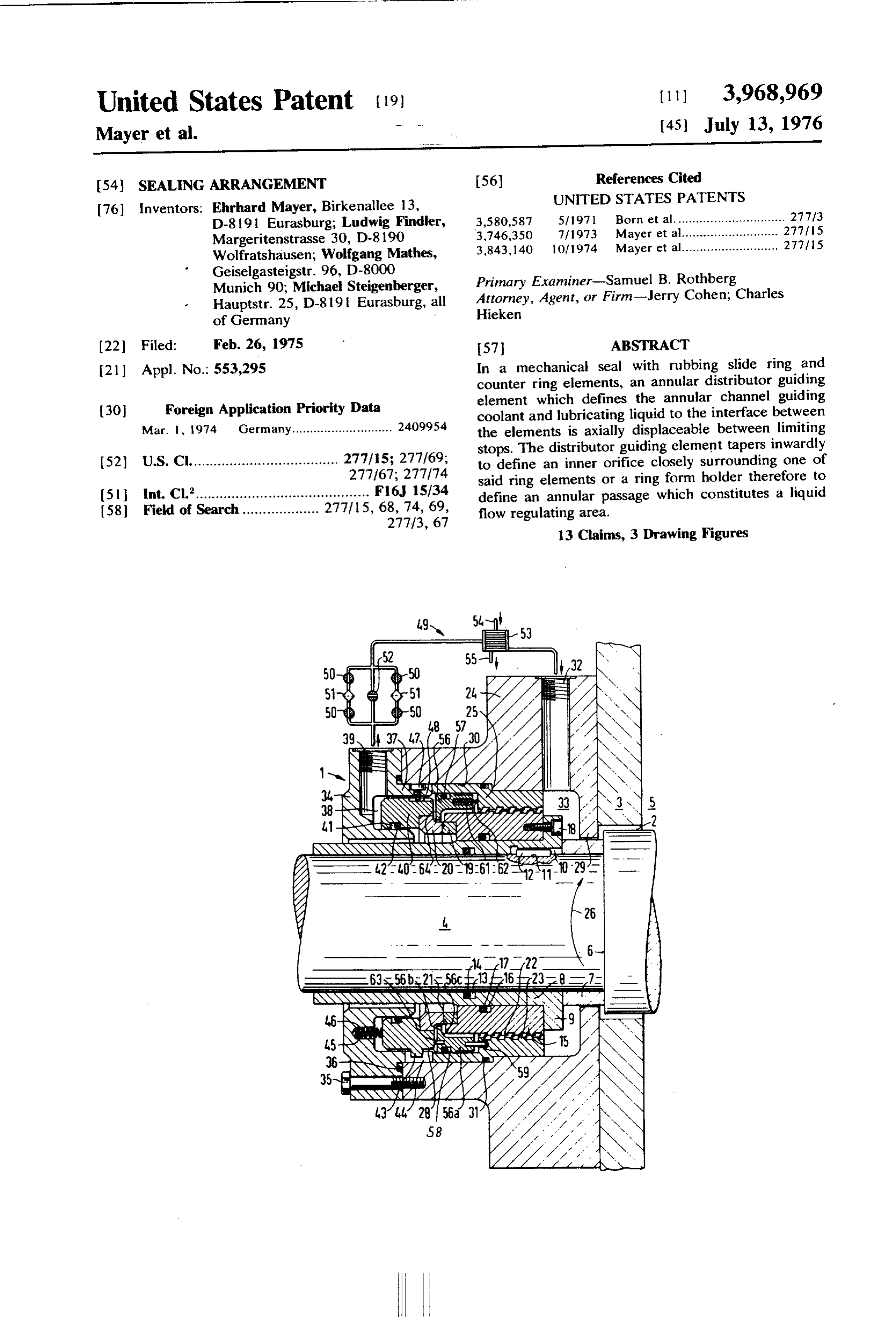
United States Patent (19) 11 3,968,969 Mayer et al. (45) July 13, 1976
54) SEALNG ARRANGEMENT 56) References Cited
UNITED STATES PATENTS
76 Inventors: Ehrhard Mayer, Birkenallee 13, 3,580,587 5/1971 Born et al............................... 277/3 D-8191 Eurasburg; Ludwig Findler, 3,746,350 7/1973 Mayer et al........................... 277/15 Margeritenstrasse 30, D-8190 3,843,140 10/1974 Mayer et al........................... 277/15 Wolfratshausen; Wolfgang Mathes,
Geiselgasteigstr. 96, D-8000 Primary Examiner-Samuel B. Rothberg
Munich 90; Michael Steigenberger, Attorney, Agent, or Firm-Jerry Cohen; Charles
22 Filed: Feb. 26, 1975 57 ABSTRACT (21) Appl. No. 553,295 In a mechanical seal with rubbing slide ring and counter ring elements, an annular distributor guiding
Foreign Application Priority Data element which defines the annular channel guiding (30) coolant and lubricating liquid to the interface between Mar. 1, 1974 Germany............................ 2409954 the elements is axially displaceable between limiting stops. The distributor guiding element tapers inwardly (52) U.S. Cl..................................... 277/15; 277/69; to define an inner orifice closely surrounding one of 277/67; 277/74 said ring elements or a ring form holder therefore to 5 int. Cl.'........................................... F16, 15/34 define an annular passage which constitutes a liquid 58 Field of Search................... 277/15, 68,74, 69, flow regulating area.
13 Claims, 3 Drawing Figures
NSN
Naziz Z
Page 2
Drawing sheet — no readable text.
Page 3
Drawing sheet — no readable text.
Page 4
Drawing sheet — no readable text.
Page 5
It is a further object of the invention that the sealing
SEANG ARRANGEMENT arrangement be economical with respect to the energy
BACKGROUND OF THE INVENTION
demand and construction expense consistent with the preceding object.
The present invention relates generally to shaft seals 5 SUMMARY OF THE INVENTION and more particularly to mechanical seal assemblies of the type comprising a fixed seal housing surrounding a Starting from a mechanical seal of the initially men rotating shaft and further comprising opposed slide ring tioned type, the above problems are solved according and counter ring elements one of which is attached to to the invention in that the distributor is supported the shaft and the other of which is attached to the fixed () displaceably in the axial direction and is guided at a housing. The ring elements rub against each other at an constant axial separation from the slide ring arranged interface and an annular distributor guiding element in the sealing housing nonrotatably and axially dis placeable against springs.
defines a channel within the seal housing through which cooling and lubricating liquid is directed at said On one hand, due to this development the distributor interface. can be arranged relative to the slide ring in a position
A screw type pump within the housing circulates which is optimal for cooling and which is unchanged liquid to the distributor from a seal housing inlet and even when the shaft moves axially during operation, increases the pressure of said liquid. After contacting and, on the other hand, it is possible to bring the dis tributor so close to this slide ring that the heated cool the periphery of said interface, the liquid continues 2) ant, through an outlet channel of the housing to an exit and permeated with bubbles of gas and steam or vapor, may be recirculated to said inlet via an external heat can be flushed out without having to tolerate any unfa exchanger. The screw pump may comprise opposed vorable increase in the amount of circulated coolant. cylindrical threaded surface with screw threads of op The distributor may be so arranged that it surrounds posite hand thereon, one of said surface being (for the circumference of the slide ring and together with instance) an inwardly facing surface with a right hand the latter forms an annular gap of less than 4 milline thread affixed to the seal housing and the other surface ters, preferably 1.5 - 3 millimeters. Furthermore, the being an outwardly facing surface with a left hand to size of this annular gap is appropriately so determined thread affixed to the rotating shaft. The two threaded second, obtain a flow speed greater than 20 centimeters per surfaces are closely spaced but noncontacting. preferably greater than 50 centimeters per 3) second.
At high and maximum circumferential speed there is According to a first embodiment of the invention, the the further requirement to attach the counter ring rig distributor being slidingly guided in a borehole formed idly to the shaft while the axially displaceable and elas in the sealing housing or a bush mounted therein, is tically prestressed slide ring is carried by the sealing prestressed by springs in the direction toward the slide housing which slide ring then must absorb an axial play 35 ring (or a support ring holding the latter) and butts of the shaft of, e.g., + 3 millimeters and also the abra against extensions of the slide ring (or of its support sion of the ring caused by wear. In such arrangement of ring.) The extensions are separator pieces or pins of the rings, the slide ring supported non rotatably in the such a length and arranged to provide an approxi sealing housing must under normal operating condi mately radial channel between the slide ring and dis tions be able to execute axial motions with a travel of, tributor which connects the said annular gap and an e.g., 6 millimeters, which must not be hindered by the exit borehole in the sealing housing leading to an exter distributor guiding element connected rigidly to the nal heat exchanger.
sealing housing. But this implies that the distributor In another embodiment, the distributor is fastened guiding element cannot be arranged in an optimal spa unmovably to the slide ring (or to a support ring hold tial configuration with respect to the stationary slide 45 ing the latter) so that there remains an approximately ring for all operating conditions and also must have radial channel corresponding to the aforesaid embodi such a large play with respect to the latter that the ment. In this channel, whose flow cross-section remains flushing out of the hot water-ring is prevented. This unaltered, there results an additional effective cooling ring of hot coolant mixed with steam bubbles having a of the slide ring (or its support ring). relatively low volume weight is formed by the influence 5) The annular gap formed between the distributor and of centrifugal forces urging cold coolant of higher vol the slide ring represents a considerable flow resistance, ume weight radially outward to the sealing casing. In so that a pressure differential is generated between the order to nevertheless achieve an adequate heat dissipa two axial sides of the distributor. This pressure differ tion, it was necessary heretofore to increase considera ential generates an axial force which acts on the distrib bly the amount of coolant conveyed in the circuit, e.g., 55 utor and whose magnitude depends on several factors, up to values of 100 liters per minute. But a consider particularly the flow cross-section of the annular gap, able power of 10 kilowatts, for example, must then be the volume of liquid conducted through the annular utilized to drive the pump mechanism. Apart from this gap and the position of the sealing elements. undesirable waste of energy to drive the pump mecha As a further development of the invention, the axial nism, this energy heating the coolant must again be 6) force exerted on the distributor is utilized to influence removed from the coolant circuit by the heat ex the contact force with which the slide ring, under the changer with increased demand for cooling water. Be action of its springs, is applied against the counter ring yond this, the dimensions of the coolant circuit are rotating with the shaft. For example, according to the increased due to the increased volume of circulated invention it is possible to reduce the contact force with coolant. 65 increasing amount of coolant conveyed through the The object of invention is to create a mechanical sealing housing, which is particularly suitable when the sealing arrangement which at high and maximum cir pump mechanism is driven by the shaft and when there cumferential speeds permits a reliable cooling. fore a reduction of the contact force und there with a
Page 6
reduction of the frictional heat is to be achieved in the 24 comprises a spring flange element 29 which has a event that the rotational speed of the shaft is raised and small bore clearing the first shaft sleeve 7 with a narrow therewith the delivery volume is raised. In another radial play. The seal housing further has a bore 30 instance it may be desirable to reduce the high contact accommodating the bushing 25 with O-ring gasket 3 force that results when a large volume of coolant is therebetween. The seal housing has an inlet bore 32 for carried through and therewith reduce the frictional receiving cooling medium which terminates in a ring heat, if the volume of coolant decreases. form chamber 33 defined between the spring flange These and other objects, features and advantages of end 29 and the above-described parts 15 and 25 and the invention will be apparent from the following de constitutes an entrance to the cylindrical pump defined scription of preferred embodiments taken in connec () by the threaded surfaces 22 and 23 of said parts. tion with the accompanying drawing, in which: Seal housing 24 has a cover 34 closing off and enter BRIEF DESCRIPTION OF THE DRAWING ing into the bore 30 and having an internal cylindrical extension clearing the second sleeve 8 with narrow
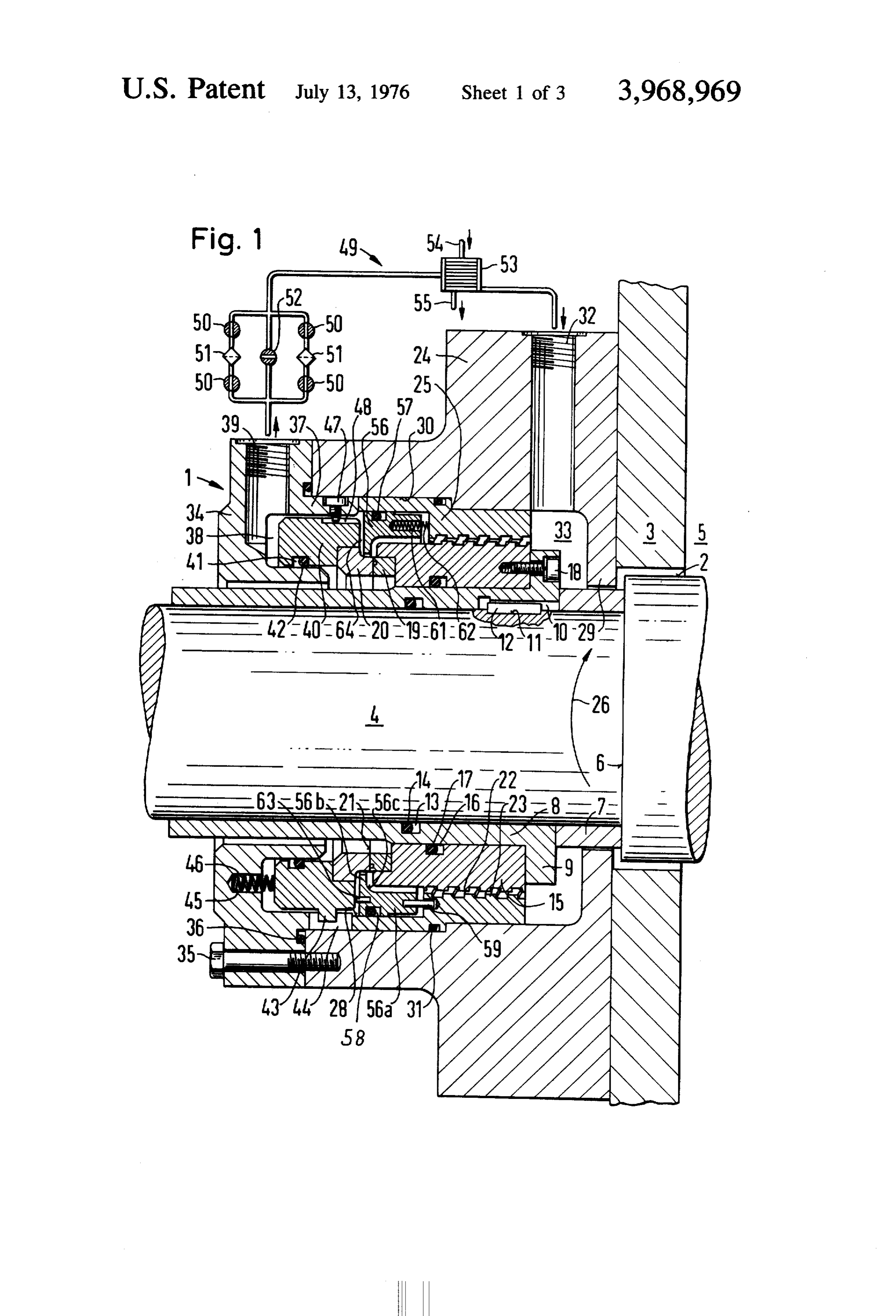
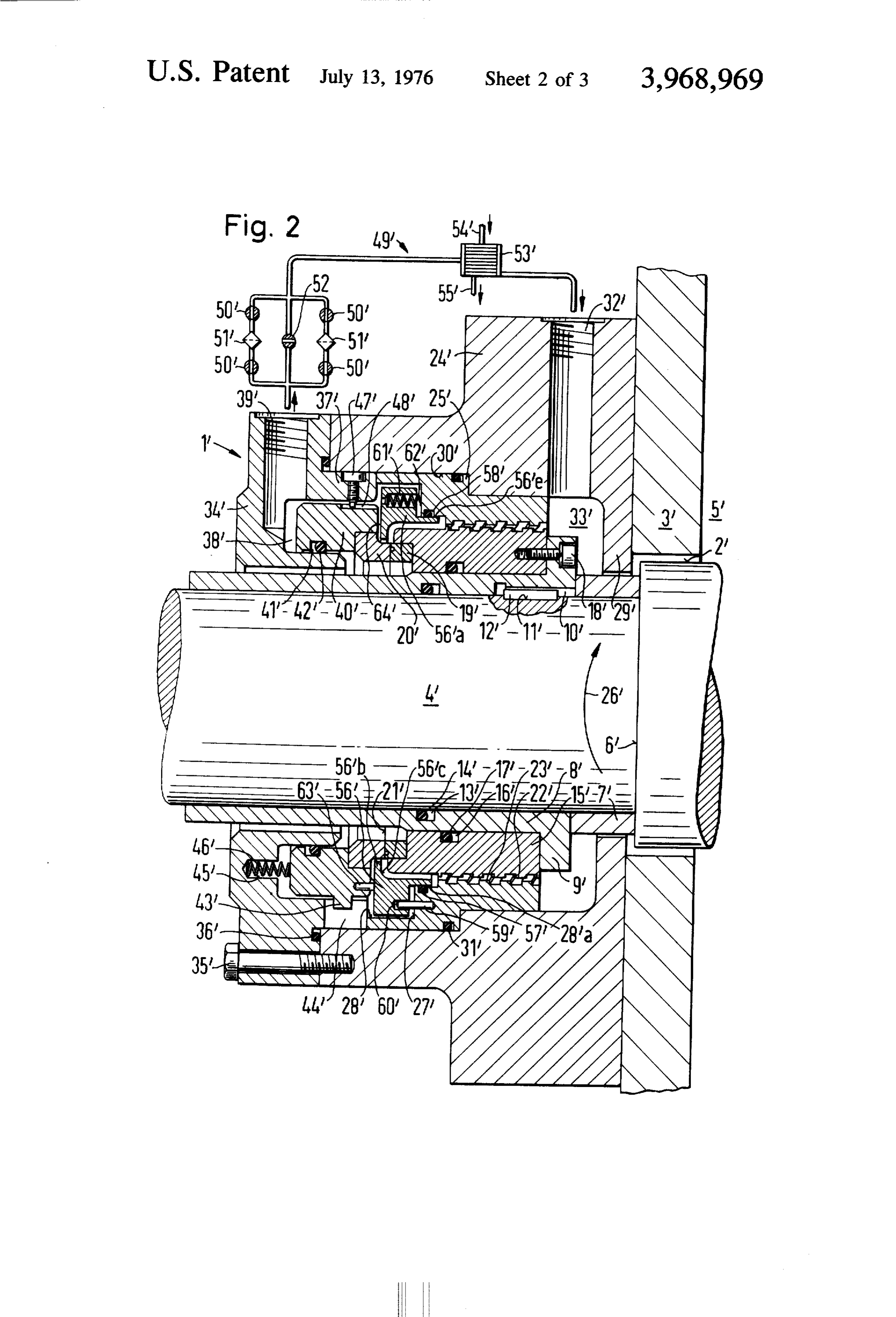
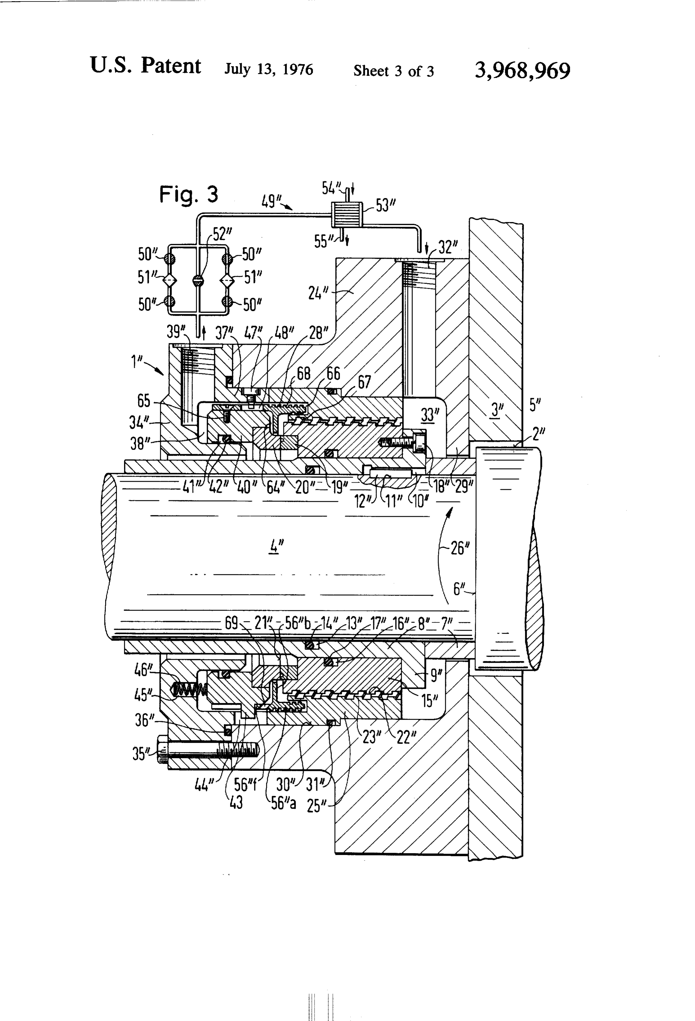
FIGS. 1, 2 and 3 are cross-section views of three radial play. A plurality of bolts, one of which is shown preferred embodiments of the invention, respectively. 5 at 35 secure the cover to the seal housing 24 in fixed DETALED DESCRIPTION OF PREFERRED relation. An O-ring gasket 36 between seal housing 24 EMBODIMENTS and cover 34 thereof prevents leakage therebetween. An outer ring extension 37 of the cover 34 extends
Referring now to FIG. 1 there is shown a slide ring within bore 30 and defines the exterior of an exit cham type sealing assembly 1 in accordance with a preferred ber 38 of ring-form which has an outlet bore 39 leading embodiment of the invention operating in connection therefrom to the exterior of the cover 34. A carrier ring with a bore 2 in a wall 3. A shaft 4 passes through the 40 is mounted on the cover 34 and has a recess 41 bore 2 into the interior of a chamber 5 defined, at least containing an O-ring gasket 42 for sealing the interface in part, by wall 3 wherein a fluid is sealed despite the 25 there between and a key 43 and swap 44 on ring 40 and break in wall 3 for hore 2 and rotating shaft 4 which cover 34 respectively or vice versa on extension 37 of passes therethrough. cover 34, respectively, or vice versa, and prevents rela A first short length cylindrical shaft sleeve 7 abutting tive rotation therebetween so that a ring 20 carried by against a collar 6 and a second long length cylindrical carrier ring 40 is secured against rotation, and, in ef shaft sleeve 8, carrying a flange 9, surround the shaft 4. fect, fixed to the seal housing 24. Corresponding recesses 10 and 11 in shaft sleeve 8 and Annularly arrayed around cover 34 are holes 45 shaft 4, respectively, and a key 12 therebetween pre containing springs 46 which bear against carrier ring 40 went relative rotation between them so that the shaft to urge ring 20 resiliently against ring 19. A peg 47 sleeve rotate together with shaft 4. An O-ring gasket 14 passes through the extension 37 of cover 34 to engage is contained in a circular recess 13 on the interior of carrier ring 34 and through its frictional engagement shaft sleeve 8 and bears against shaft 4. 35 therewith, preferably in a clot 48 thereof, limits the There is also shown on the second shaft sleeve 8, a effect of springs 46 and also as a stop to displacement carrier ring 15, with an interior circular recess 16 con of ring 40 by string 46 through engagement with the taining an O-ring gasket 17, which is secured to the back end wall of slot 48 or equivalent means. second shaft sleeve 8 by a plurality of bolts passing The outlet bore 39 leads to a recirculating heat ex through flange 9, one of which is indicated at 18. The 4) change loop 49 which returns to the inlet passage 32 of carrier ring 15 carries a cylindrical counter ring num the seal housing after the passage, conducted by selec ber 19 which bears against a slide ring 20, supported in tive operation of valves 50 or 52 through filters 51 and a manner described below, and defines a sealing inter heat exchanger 53, which also has passages for inlet face 2 therebetween. (54) and outlet (55) of heat exchange fluid. The slide ring assembly further comprises a main 45 The critical point of flow through the loop is the housing 24 demountably securable to the wall 3 by proper supply of cooling fluid to the interface 21 be bolts or other means, (not shown) and containing an tween the slide ring and counter ring and the converg orifice of diameter smaller than bore 2 of wall 3 for ing passage thereto is defined by an inwardly converg close fitting, but noncontacting, passage of the first ing curved distributor guide member 56 which com shaft sleeve 7 therein. The above described carrier ring prises a smooth entrance section 56a and a radially 15 has an external spirally threaded surface 22 and the inwardly extending end 56b joined by a smoothly seal housing 24 carries an interior bushing 25 therein curved concave shoulder portion 56c. The member 56 which has interior spirally threaded surface 23 working is sealed within holder ring 25, which carries it, by an together with the thread 22 to define a fluid pump, the O-ring gasket 57 held in an annular recess 58. particular construction of such cooperating threaded 55 Annularly arrayed around the front end (extending surfaces being as described in U.S. Pat. No. 3,746,350 towards space 5) of the tube forming part 56a are pegs or U.S. patent applicaton Ser. No. 308,006, filed Nov. 59 and coil springs 62 supported in holes in part 56a 20, 1972 but preferably constructed more specifically (holes 61 contouning the springs 62) and extending to as described below. an inner shoulder 27 of bushing 25. Similar pegs 63, in The pump defined by threads 22 and 23 feeds cooling f) an annular array, extend from carrier ring 40 to distrib medium to the outer periphery of the interface 21 be utor 56. Springs 46 in holes 45 of cover 34 extend tween the slide ring and counter ring via an inwardly carrier ring 40. A small annular radial channel of 1,5-3 converging guide channel which is completely annular millimeters on radius is defined in the space between and defined in part by a rounded corner of the carrier the inner edge of part 56th and the outside of slide ring ring 15 opposing an inwardly converging curved dis 65 20. Cooling water guided to the sealing interface of tributor guide member 56, described below. The bush rings 19, 20 by distributor 56 passes through this chan ing 25 is secured in the seal housing and with it to the nel and up through a radial annular channel 64 defined wall 3 as a fixed member. An inner portion of housing between distributor 56 and the forward face of ring 40
Page 7
S 6 with a minimum axial span of such channel established between 56'b and slide ring 20' and through chamber by pegs 63. The water can then pass out through mani 64'.
fold 38 and bore 39 to the external heat exchanger It is evident that those skilled in the art, once given described above. the benefit of the foregoing disclosure may now make A flow of over 50 cm/sec. through channel 64 is 5 numerous other uses and modifications of, and depar established by the pressure head of pumped water and tures from the specific embodiments described herein the small size of the annulus between 56b and 20. The without departing from the invention concepts. Conse resistance to flow up channel 64 at such speed is such quently, the invention is to be construed as embracing that there is a lower pressure on the back side than on O each and every novel feature and novel combination of the front side of distributor 56. This together with the features present in, or possessed by, the apparatus and action of springs 62 and 46 tends to float distributor 56 techniques herein disclosed and limited solely by the against pegs 63. However under some transient condi scope and spirit of the appended claims. tions of flow, the fluid distributor S6 will float towards What is claimed is:
hushing 25 and pegs 59 set definite limits to such move 5 1. Mechanical seal assembly for an axially extending ment. In this arrangement distributor 56 is tolerant of elongated shaft comprising, axial excursion of shaft 4 and nevertheless maintains means defining an annular slide ring seal with rub optimum position. bing slide ring and counter ring elements, Changing pressure in channel 64 can also force car means defining a housing containing said seal and rier ring 40 back against springs 46 to define the sealing rotationally fixedly mounting said slide ring, force that slide ring 20 (carried by ring 40) exerts said counter ring being mountable on said shaft via against counter ring 19 at sealing interface 21. For counter ring support structure, instance when the speed of shaft 4 increases, the pump means defining a coolant circuit that conducts a cool defined by threads 23 and 24 delivers more fluid and ant through the seal housing in an axial direction this develops a pressure easing ring 40 back against the 25 and including a pump device with inlet and outlet action of springs 46 to reduce the sealing force at inter ends for pumping coolant liquid through the cir face 21. This effects a desirable reduction in frictional cuit, which circuit further comprises an annular heat generated at interface 21. space surrounding said seal and distributor guiding In the FIG. 2 and 3 embodiments, parts similar to means that conduct the coolant to an edge of the those of the FIG. 1 embodiment are indicated by the 30 sealing interface of the slide ring and counter ring same reference numerals MTL one and two prime within said annular space and which are sealed with symbols added, respectively, and reference may be had respect to the seal housing, to the discussion of FIG. 1 above for a description of and further comprising means for supporting and such parts. displacing the distributor guiding means in said The differences are as follows: axial direction and constructed and arranged to The bushing 25" (which carries the internal threaded 35 maintain the distributor guiding means at a con surface 23) in FIG. 2 differs from the bushing 25 of stant axial distance from the slide ring, FIG. 1 by providing a larger bore therein indicated at the slide ring being mounted in the seal housing in a 28' allowing a larger distributor element 56' which rotationally fixed manner and being axially dis creates a greater radius for the radial space 64". The 40 placeable against springs. distributor element 56' has a tubular extension 56'd 2. Mechanical seal assembly in accordance with terminating in a circumferential wall 56'e which mates claim 1 wherein the distributor guiding means com with a bore 28'a and the seal therebetween is com prises an annulus shape surrounding the slide ring and pleted by an O-ring gasket 57" in a groove 58' in bore being closely spaced therefrom and also being down 28'a. It will be noted that the sealing interface defined 45 stream of the pump outlet and wherein the radial inside at 56'a/28'a in FIG. 2 is at a location of reduced diame width of the radial annular gap formed between the ter compared to the corresponding sealing interface distributor guiding means and the periphery of the slide between bore 28 and distributor 56 in FIG. 1. ring is of such a size in relation to the pump device that The FIG. 1 embodiment allows a greater axial force the flow speed of the coolant is greater than 20 centi to be applied to the distributor 56 than the FIG. 2 5) meters per second.
embodiment allows for distributor 56' because the 3. Mechanical seal assembly as claimed in claim 2, available working surface of the latter exposed to the wherein the annular gap formed between the distribu pressurized working fluid at the outlet of the screw tor guiding means and the outer periphery of the slide thread pump. ring has a radial inside width of less than 4 millimeters. In the further embodiment of FIG. 3, a modified 55 4. Mechanical seal assembly in accordance with distributor 56' has tubular extension 56' f to the left of claim 2 and further comprising means defining an axi the central apertured disc 56'b as well as a tubular ally extending bore within said annular space extension to the right, 56'a. Holder ring 40' has a and wherein the distributor guiding means are slid reduced outer diameter (compared to 40 and 40' of the ingly guided in said bore and are prestressed in a FIGS. 1 and 2 embodiments) to accommodate tube 6) direction toward the slide ring, 56'f. Bolt 47' extending into a groove 48' and one or and means defining butting engagement of the dis more screws 65 connecting tube 56''f' to ring 40' pre tributor guiding means against the slide ring sup vent rotation of the ring 40'? distributor 56' subassem port structure via spacing pieces in such a manner bly. that there remains a radial channel between the A shoulder 27' on bushing 25' forms an annular support structure and distributor which is joined to space 66 and annular internal grooves 67 and external 65 said annular gap and which is connected to an exit grooves 28' on tubular extension 56'a form a throttle in the seal housing.
bypass path for pressurized fluid working around dis 5. Mechanical seal assembly in accordance with tributor 56' rather than passing through the radial slit claim 2 wherein the distributor guiding means are fas
Page 8
tened immovably to the slide ring structure and define thread pump which is arranged inside the seal housing therewith a radial channel for radial outward move and comprises an outer thread and an inner thread of ment of coolant from the seal which is joined to said opposite hand surrounding coaxially with slight radial annular gap and which is connected to an exit of the play on opposing cylindrical surfaces one of which is seal housing. connected rigidly to the seal housing and the other of 6. Mechanical seal assembly in accordance with which rotates with a shaft to be sealed off by said seal claim 5 wherein the diameter of the peripheral surface and has the same pitch direction as the shaft rotation acting to seal off the distributor guiding means with direction to raise bearing force of the counter ring with respect to the seal housing defines the outer end of said () increasing rotation speed of the shaft. radial channel and is chosen in accordance with the 10. Mechanical seal assembly in accordance with degree of a desired influence of the bearing force of the claim 1 wherein the distributor guiding means consists slide ring against the counter ring as a function of the essentially of a tubular part and a flangetype part di volume of the coolant conducted past said annular gap, rected radially inward from the latter. with the degree of the influence rising with increasing 5 11. Mechanical seal assembly in accordance with deviation of diameter from a mean diameter of the claim 10 wherein the tubular part of the distributor annular gap between the distributor guiding means and guiding means with an outer cylindrical peripheral slide ring. surface is displaceably guided in a bore formed in a 7. Mechanical seal assembly in accordance with bushing in the seal housing, and that the seal of the claim 6 wherein a flow direction of the coolant from distributor guiding means is arranged between this the counter ring to the slide ring is provided to influ 2) peripheral surface and the bore. ence the bearing force in the sense of a reduction and 12. Mechanical seal assembly in accordance with that an opposite flow direction is provided to influence claim 10 wherein a tubular part projects from each it in the reverse sense. axial side of the flangetype part, that one tubular part is 8. Mechanical seal assembly in accordance with pushed onto the support ring of the slide ring and is claim 1 wherein the pump device is formed as a screw sealingly fastened and adjacent to the flangetype part, thread pump which is arranged inside the seal housing is broken through by at least one slit, and that the other and comprising an outer thread and an inner thread of tubular part forms a contactless seal by entering with opposite hand surrounding it coaxially with slight radial slight radial play into an annular space which is open in play on opposing cylindrical surfaces, one of which is the axial direction and which is formed in the seal hous connected rigidly to the seal housing and the other of 3) ing.
which rotates with a shaft to be sealed off by said seal 13. Mechanical seal assembly in accordance with and has a pitch direction opposite to the shaft rotation claim 12 wherein unconnected annular grooves are cut direction to reduce the bearing force of the counter into the inner and/or outer peripheral surface of the ring with increasing rotation speed of the shaft. 35 section of the tubular part entering into the annular 9. Mechanical seal assembly in accordance with space.
claim 1 wherein the pump device is formed as a screw k k sk xk sk
Provenance
- Collection
- Cited prior art
- Original PDF
- patentimages.storage.googleapis.com →
- Filed
- 1975-02-26
- Pages
- 8
- Method
- pdftotext (the PDF's own text layer) + pdftoppm 300dpi page scans
- Source
- Google Patents bibliographic record
- Granted
- 1976-07-13
- Inventors
- Ehrhard Mayer; Ludwig Findler; Wolfgang Mathes; Michael Steigenberger
- Transcribed from
- patentimages.storage.googleapis.com →