patent · US6285090
Low-speed directly driven wind turbine
4 September 2001
Page 1 — bibliographic record
(12) United States Patent (10) Patent No.: US 6,285,090 B1 Brutsaert et al. (45) Date of Patent: Sep. 4, 2001
(54) LOW-SPEED DIRECTLY DRIVEN WIND 4,686,376 8/1987 Retz ....................................... 290/42 TURBINE 5,986,378 11/1999 Caamano ............................. 310/216 (75) Inventors: Patrick Brutsaert, Recduignies; FOREIGN PATENT DOCUMENTS Jean-Marc Canini, Aibes; Raymond 902092 7/1985 (BE).
Michaux, Solre le Chateau, all of (FR) 2623233 5/1976 (DE).
(73) Assignee: Jeumont Industrie, Courbevoie (FR) 4402184 1/1994 (DE).
(*) Notice: Subject to any disclaimer, the term of this 2551142 3/1985 (FR). patent is extended or adjusted under 35 wo. g1. 8)
U.S.C. 154(b) by 0 days. WO9422204 9/1994 (WO).
(21) Appl. No.: 09/367,010 OTHER PUBLICATIONS (22) PCT Filed: Mar. 9, 1998 Chen et al., “A Variable-Speed, Permanent-Magnet, Wind (86) PCT No.: PCT/FR98/00468 Turbine Generator And Its Control', Power Engineering S371 Date: Nov. 8, 1999 Conference, vol. 2, Sep. 1995, pp. 517-520. Jefferson et al., “The Application Of Flywheels In Short
S 102(e) Date: Nov. 8, 1999 Term Energy Storage”, Alternative Energy Systems, Elec trical Integration and Utilization Conference, Sep. 1984, pp.
(87) PCT Pub. No.: WO98/40627 97-104.
PCT Pub. Date: Sep. 17, 1998 * cited by examiner (30) Foreign Application Priority Data
Primary Examiner Nicholas Ponomarenko
Mar. 10, 1997 (FR) .................................................. 97 O28O8 (74) Attorney, Agent, or Firm-Leydig, Voit & Mayer, Ltd. (51) Int. Cl." ........................................................ F03D 9/00 (57) ABSTRACT (52) U.S. Cl. ................................ 290/55; 290/44; 310/216 (58) Field of Search .................................. 290/43, 44, 52, An electrical energy production System includes a Wind 290/54, 55; 310/216 turbine having blades mounted on a Support and which rotationally drive an alternator. The alternator includes at (56) References Cited least one module having at least one rotor disk and one Stator disk centered on an axis of the Support and all of the rotor
4,075,500 2/1978 Oman et al. ........................... 290/55 4,140,433 2/1979 Eckel ....................................... 415/2 17 Claims, 6 Drawing Sheets
Page 2
Drawing sheet — no readable text.
Page 3
Drawing sheet — no readable text.
Page 4
Drawing sheet — no readable text.
Page 5
Drawing sheet — no readable text.
Page 6
Drawing sheet — no readable text.
Page 7
Drawing sheet — no readable text.
Page 8
LOW-SPEED DIRECTLY DRIVEN WIND Finally, the power of the Synchronous machine is neces TURBINE sarily limited by the diameter of the rotor.
Excitation of Such a machine with a wound rotor implies
The present invention is in the area of wind turbine either the use of a set of Slip rings and brushes, constraint of power production. maintenance generators, or the inclusion of an auxiliary ac It concerns a System for the production concerns elec exciter and a set of shaft-mounted rectifiers, which further trical energy activated by the force of the wind on the blades increase the mass of the assembly. of a wind turbine. It may be noted also that, in general, wind turbine BACKGROUND assembly is difficult. It requires very tall cranes able to lift heavy members of great bulk. Thus, assembly requires a
Different types of wind turbines having an essentially Significant engineering effort. For that reason, assembly of Vertical shaft and an essentially horizontal axis or even an Such wind turbines in countries that do not have the appro essentially vertical axis are known. priate equipment at their disposal is not possible. The demand for energy increases constantly as fossil fuel 15 reserves diminish. SUMMARY OF THE INVENTION This is why electrical companies are beginning to inte The object of the invention is the provision of a system for grate wind turbine energy with other conventional energy the production of energy associated with a wind turbine that Sources. Thus, numerous wind turbine power Stations have does not require a multiplier, while facilitating construction been installed. of the wind turbine and reducing the noise generated by the Most wind turbines designed for energy production wind turbine during operation.
include a rapid asynchronous generator coupled to a This System for the production of electrical energy is multiplier, itself driven by the hub on which the wind turbine asSociated with a wind turbine comprising blades fixed on a blades are mounted. Mention may be made especially of Support and driving in rotation the rotor of an alternator. Micon wind turbines. 25
For example, a 1500-rpm asynchronous generator and a least This alternator is of the discoid type and consists of at one module comprising at least a rotor disk and a Stator multiplier driven at a speed of 27 rpm correspond to 600 kW. disk centered on the axis of the blade Support, the modules All these elements are placed in a nacelle, rotationally being assembled in Such a way that all the rotor and Stator mounted to one end of the shaft. The height of the shaft is disks are coaxially arranged.
generally between 30 and 60 m. The direct driving of the rotor disk(s) by the wind turbine Also within the nacelle is a nacelle orientation control blades renders the presence of a multiplier unnecessary and System and, in Some cases, a blade angle of attack control possibly permits the complete discontinuance of the hydrau System. This allows the blades to be oriented as a function lic generator.
of the wind. In particular, if the wind becomes too strong, the In addition, the modular design of the alternator allows for pitch relative to the wind is modified for reasons of exploi 35 easy adaptation to System power. tation and Safety.
The following characteristics may likewise be taken into
These Systems, Such as the multiplier, require the presence account, of at least one hydraulic generator in the nacelle. individually or according to all technically possible combinations:
A global wind turbine control System is generally pro
Vided. It uses a controller that may control the blade angle 40 theSupport, system includes a shaft driven in rotation by the blade the rotor disk(s) being integrated with Said of attack, the nacelle position, and/or the coupling of the generator to the Supply network. shaft,
AS the asynchronous generator has one or two fixed the blade Support includes the alternator frame, which Speeds, its operation on the Supply network is not optimal 45 includes the alternator rotor disk(s), over the entire range of wind Speeds. a module has a rotor disk arranged, between two Stator Low-speed directly driven wind turbines have also been disks or a Stator disk between two rotor disks, installed. Of note are those manufactured by Enercon. They the rotor disk or disks have permanent magnets, include a large-diameter radial-flux Synchronous machine. the stator disks are affixed to the wind turbine nacelle, The rotor disc of the machine is driven by a shaft, which, in 50 an ac(-dc)-ac converter is placed between the alternator turn, is driven by the wind turbine blades. and the Supply network,
The Synchronous machine feeds the Supply network the ac(-dc)-ac converter consists of a rectifier and an through an ac-dc-ac converter. Such a converter allows the inverter, both controlled by pulse-width modulation, Supply network to be fed at the appropriate frequency and the wind turbine includes a system for global control of Voltage. 55 the operating parameters.
In Such wind turbines, all the control Systems are The invention also concerns a wind turbine equipped with electrical, especially those that ensure blade pitch or nacelle an energy production System in accordance with the inven orientation, as well as the braking System. tion and in which certain parts, especially the blades, their These wind turbines allow dispensing with the multiplier Support, the discoid alternator, and/or the nacelle are manu and the hydraulic generator. They can also deliver power 60 factured Separately and are finally assembled at the top of the even at low wind Speed. wind turbine shaft.
However, they include an air-cooling System that gener The invention also concerns an array of wind turbines ates a significant noise level. each equipped with a System for the production of electrical In addition, the presence of rotor field windings implies energy according to the invention and an ac-dc converter. excitation losses that become appreciable at low wind 65 The output of each of these converters is connected to at Speeds, Significantly diminishing the efficiency of the assem least one dc-ac converter and the common-node output of bly. the dc-ac converters is connected to the Supply network.
Page 9
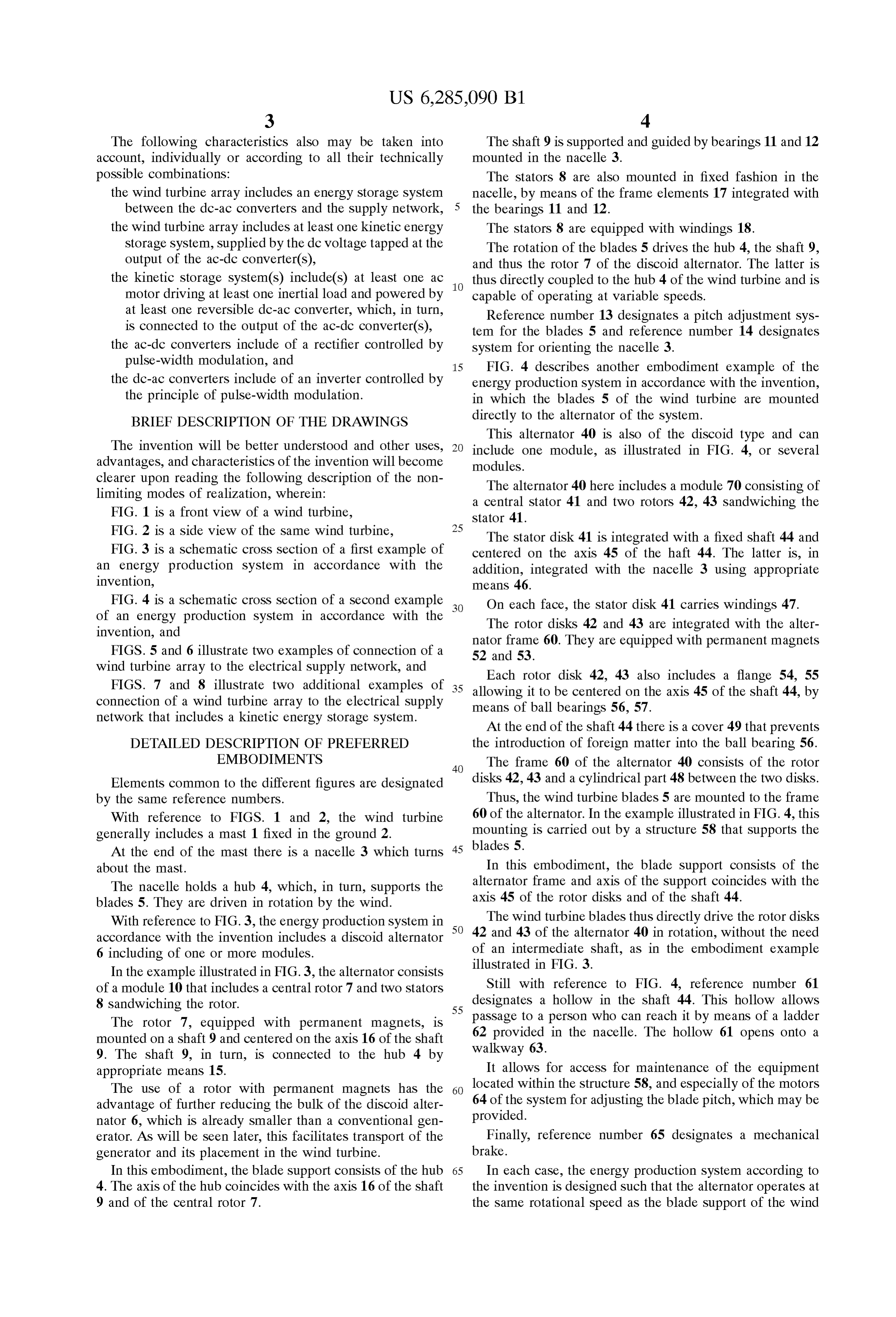
The following characteristics also may be taken into The shaft 9 is supported and guided by bearings 11 and 12 account, individually or according to all their technically mounted in the nacelle 3.
possible combinations: The stators 8 are also mounted in fixed fashion in the the wind turbine array includes an energy Storage System nacelle, by means of the frame elements 17 integrated with between the dc-ac converters and the Supply network, the bearings 11 and 12.
the wind turbine array includes at least one kinetic energy The stators 8 are equipped with windings 18. Storage System, Supplied by the dc voltage tapped at the The rotation of the blades 5 drives the hub 4, the shaft 9, output of the ac-dc converter(s), and thus the rotor 7 of the discoid alternator. The latter is the kinetic Storage System(s) include(s) at least one ac thus directly coupled to the hub 4 of the wind turbine and is motor driving at least one inertial load and powered by capable of operating at variable Speeds. at least one reversible dc-ac converter, which, in turn, Reference number 13 designates a pitch adjustment Sys is connected to the output of the ac-dc converter(s), tem for the blades 5 and reference number 14 designates the ac-dc converters include of a rectifier controlled by System for orienting the nacelle 3.
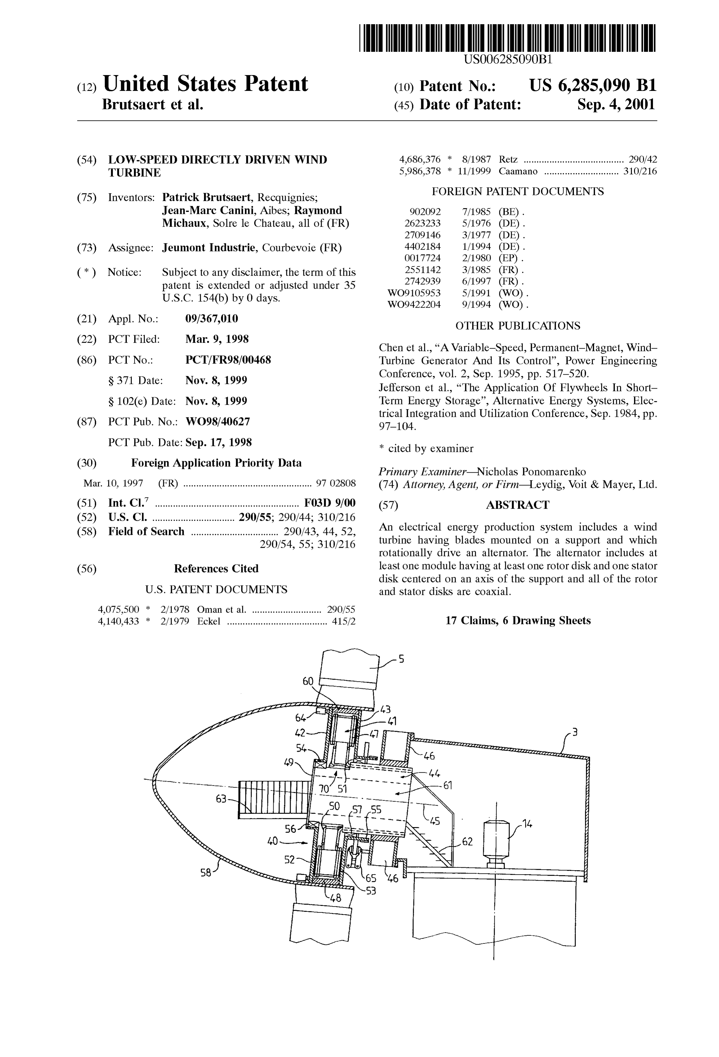
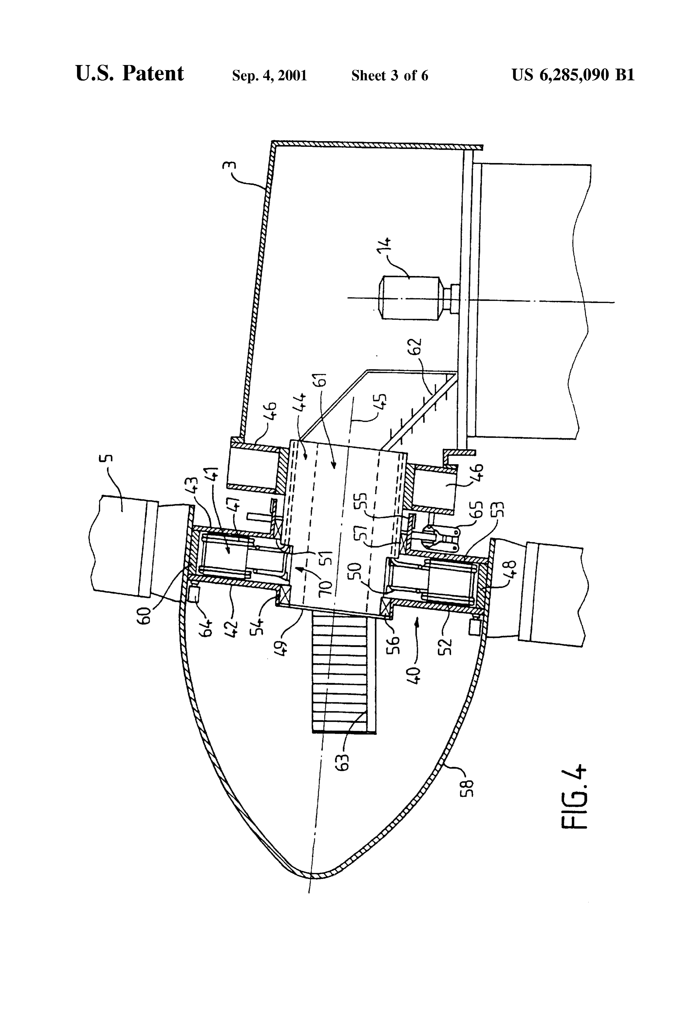
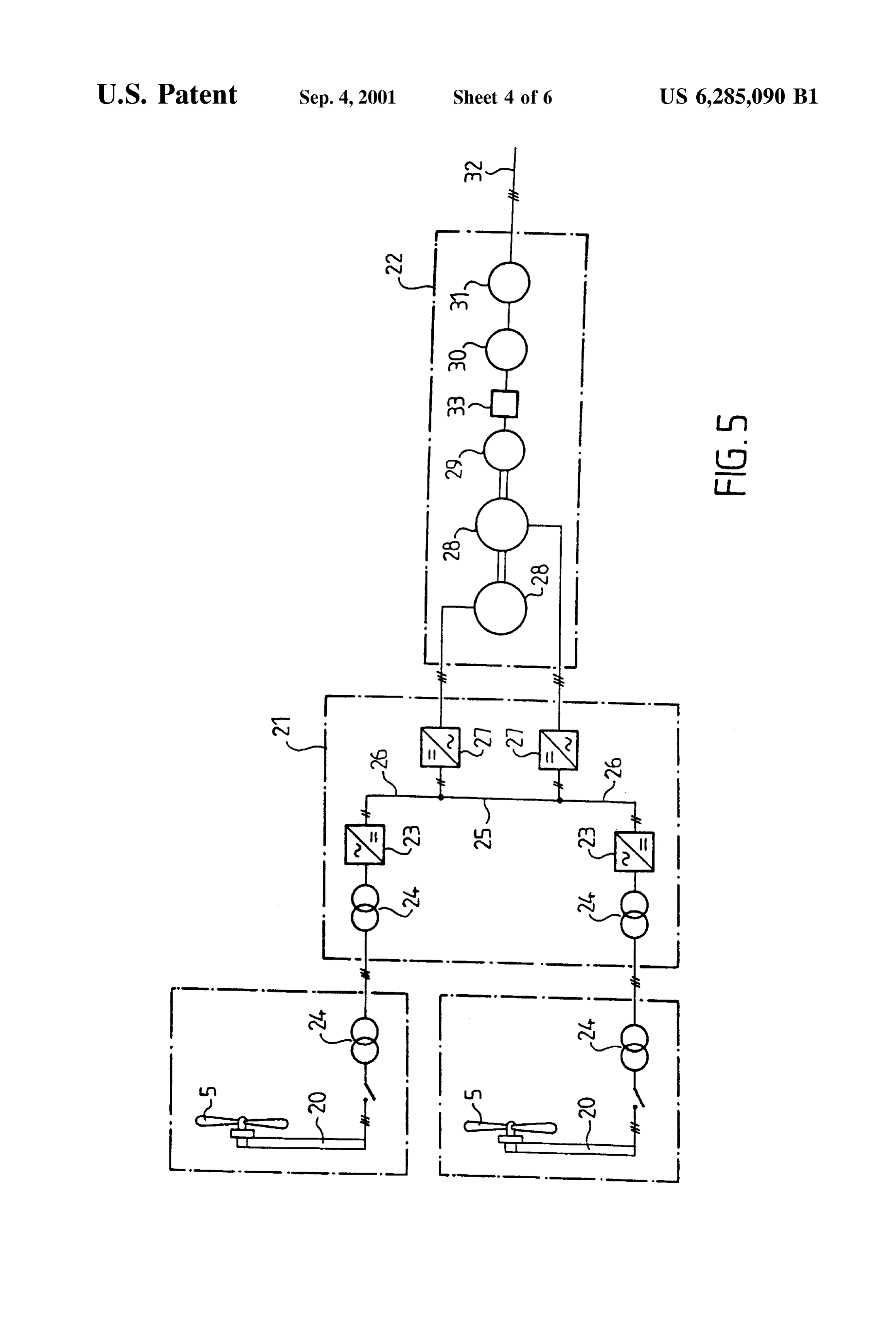
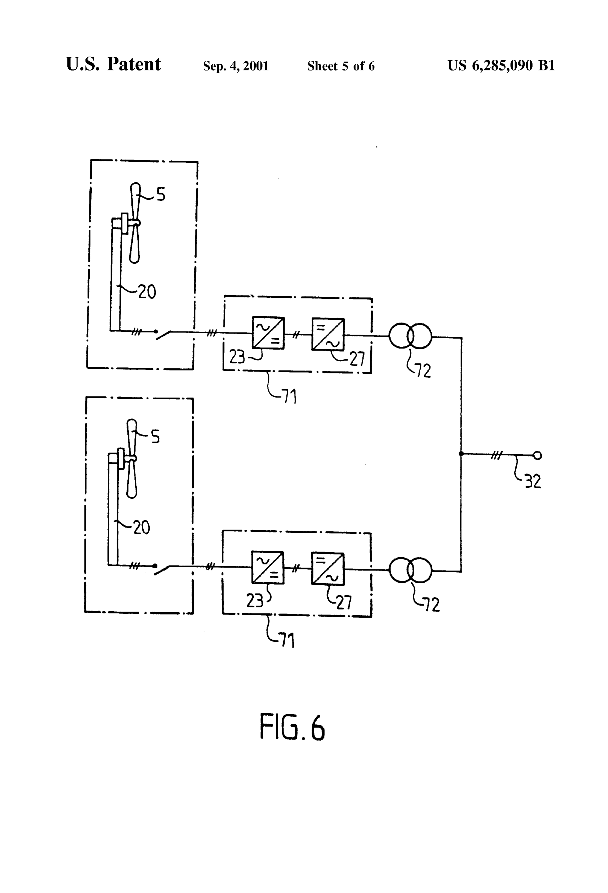
pulse-width modulation, and 15 FIG. 4 describes another embodiment example of the the dc-ac converters include of an inverter controlled by energy production System in accordance with the invention, the principle of pulse-width modulation. in which the blades 5 of the wind turbine are mounted BRIEF DESCRIPTION OF THE DRAWINGS directly to the alternator of the system. This alternator 40 is also of the discoid type and can
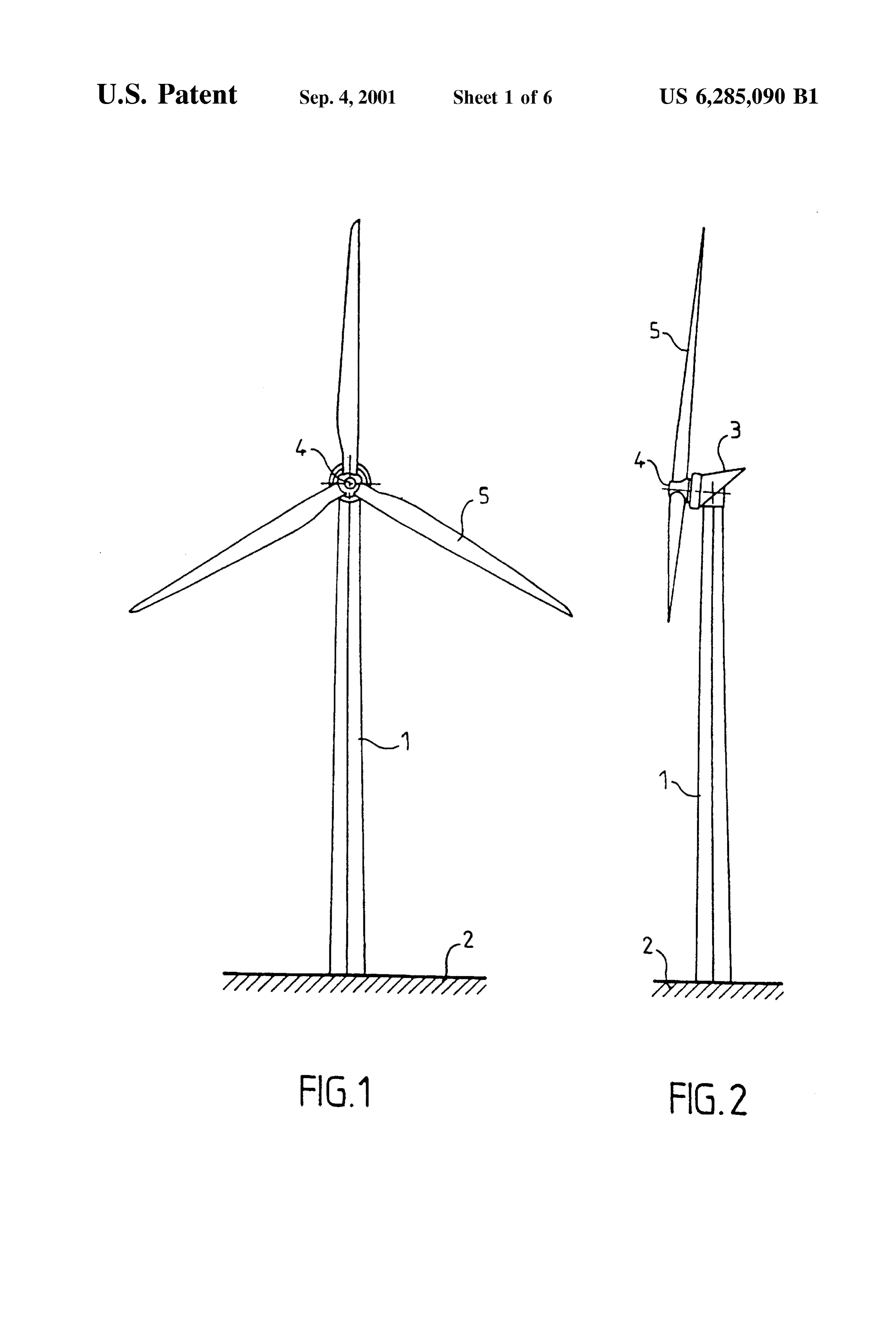
The invention will be better understood and other uses, include one module, as illustrated in FIG. 4, or several advantages, and characteristics of the invention will become modules.
clearer upon reading the following description of the non The alternator 40 here includes a module 70 consisting of limiting modes of realization, wherein: a central stator 41 and two rotors 42, 43 sandwiching the FIG. 1 is a front view of a wind turbine, stator 41.
FIG. 2 is a side view of the same wind turbine, 25
The stator disk 41 is integrated with a fixed shaft 44 and
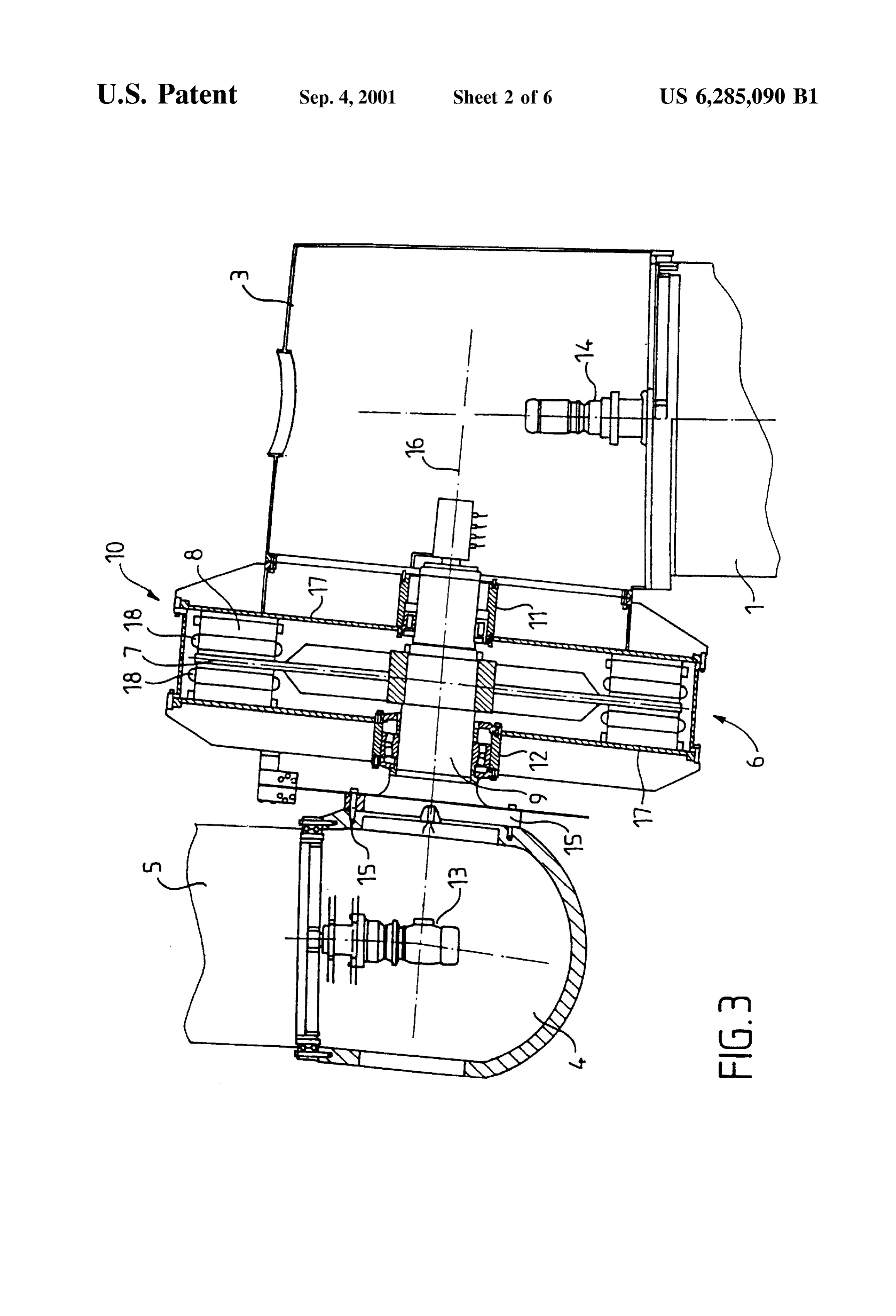
FIG. 3 is a Schematic croSS Section of a first example of centered on the axis 45 of the haft 44. The latter is, in an energy production System in accordance with the addition, integrated with the nacelle 3 using appropriate invention, means 46.
FIG. 4 is a Schematic croSS Section of a Second example On each face, the stator disk 41 carries windings 47. of an energy production System in accordance with the The rotor disks 42 and 43 are integrated with the alter invention, and nator frame 60. They are equipped with permanent magnets FIGS. 5 and 6 illustrate two examples of connection of a 52 and 53.
wind turbine array to the electrical Supply network, and
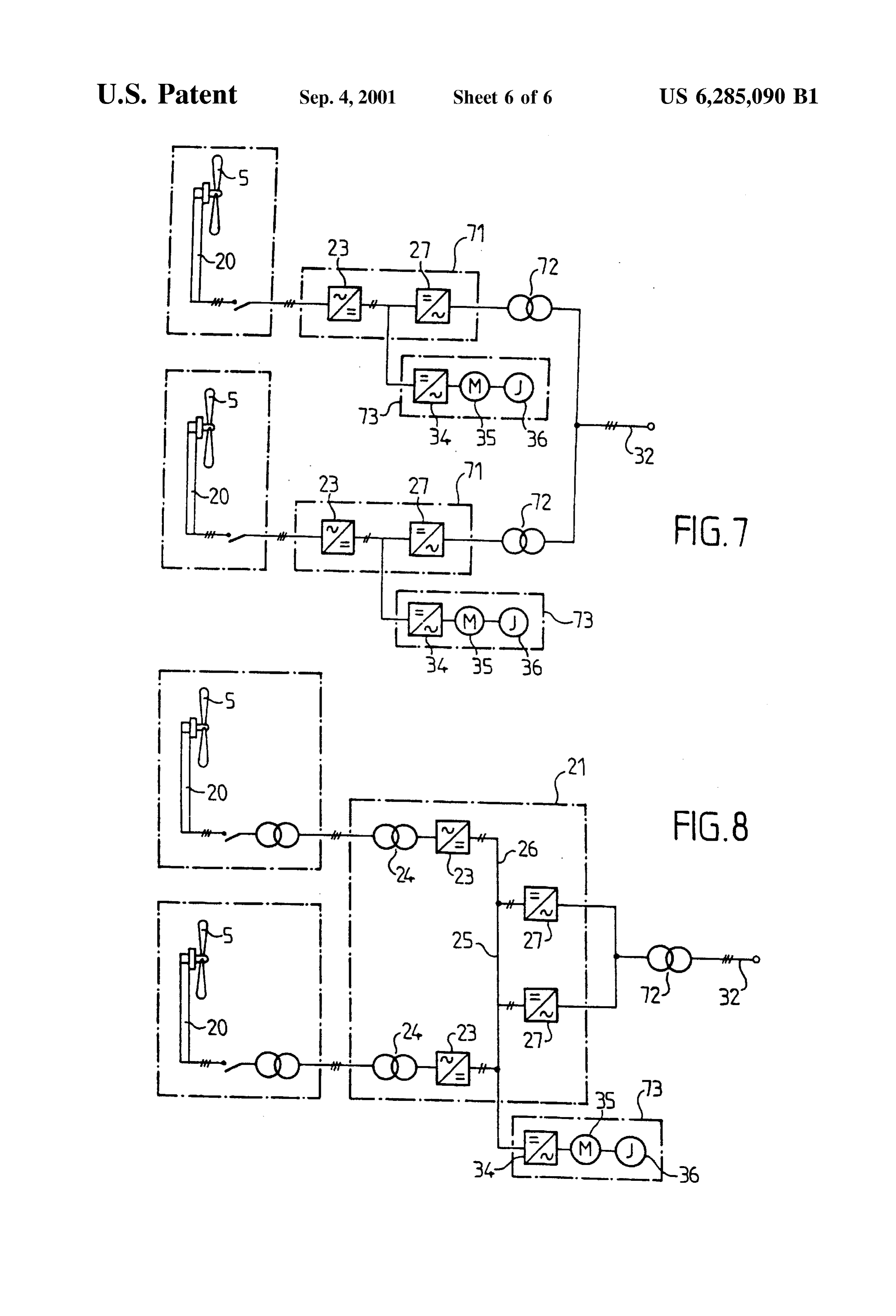
FIGS. 7 and 8 illustrate two additional examples of 35 Each rotor disk 42, 43 also includes a flange 54, 55 connection of a wind turbine array to the electrical Supply allowing it to be centered on the axis 45 of the shaft 44, by means of ball bearings 56, 57.
network that includes a kinetic energy Storage System.
At the end of the shaft 44 there is a cover 49 that prevents
DETAILED DESCRIPTION OF PREFERRED the introduction of foreign matter into the ball bearing 56. EMBODIMENTS The frame 60 of the alternator 40 consists of the rotor
Elements common to the different figures are designated disks 42, 43 and a cylindrical part 48 between the two disks. by the same reference numbers. Thus, the wind turbine blades 5 are mounted to the frame With reference to FIGS. 1 and 2, the wind turbine 60 of the alternator. In the example illustrated in FIG. 4, this generally includes a mast 1 fixed in the ground 2. mounting is carried out by a structure 58 that Supports the At the end of the mast there is a nacelle 3 which turns 45 blades 5.
about the mast. In this embodiment, the blade support consists of the The nacelle holds a hub 4, which, in turn, Supports the alternator frame and axis of the Support coincides with the axis 45 of the rotor disks and of the shaft 44.
blades 5. They are driven in rotation by the wind.
With reference to FIG. 3, the energy production system in 50 The wind turbine blades thus directly drive the rotor disks accordance with the invention includes a discoid alternator 42 and 43 of the alternator 40 in rotation, without the need 6 including of one or more modules. of an intermediate Shaft, as in the embodiment example illustrated in FIG. 3.
In the example illustrated in FIG. 3, the alternator consists of a module 10 that includes a central rotor 7 and two stators Still with reference to FIG. 4, reference number 61 8 Sandwiching the rotor. 55 designates a hollow in the shaft 44. This hollow allows
The rotor 7, equipped with permanent magnets, is passage to a person who can reach it by means of a ladder mounted on a shaft 9 and centered on the axis 16 of the shaft 62 provided in the nacelle. The hollow 61 opens onto a 9. The shaft 9, in turn, is connected to the hub 4 by walkway 63.
appropriate means 15. It allows for access for maintenance of the equipment The use of a rotor with permanent magnets has the 60 located within the structure 58, and especially of the motors 64 of the system for adjusting the blade pitch, which may be advantage of further reducing the bulk of the discoid alter provided.
nator 6, which is already Smaller than a conventional gen erator. AS will be seen later, this facilitates transport of the Finally, reference number 65 designates a mechanical generator and its placement in the wind turbine. brake.
In this embodiment, the blade support consists of the hub 65 In each case, the energy production System according to 4. The axis of the hub coincides with the axis 16 of the shaft the invention is designed Such that the alternator operates at 9 and of the central rotor 7. the same rotational Speed as the blade Support of the wind
Page 10
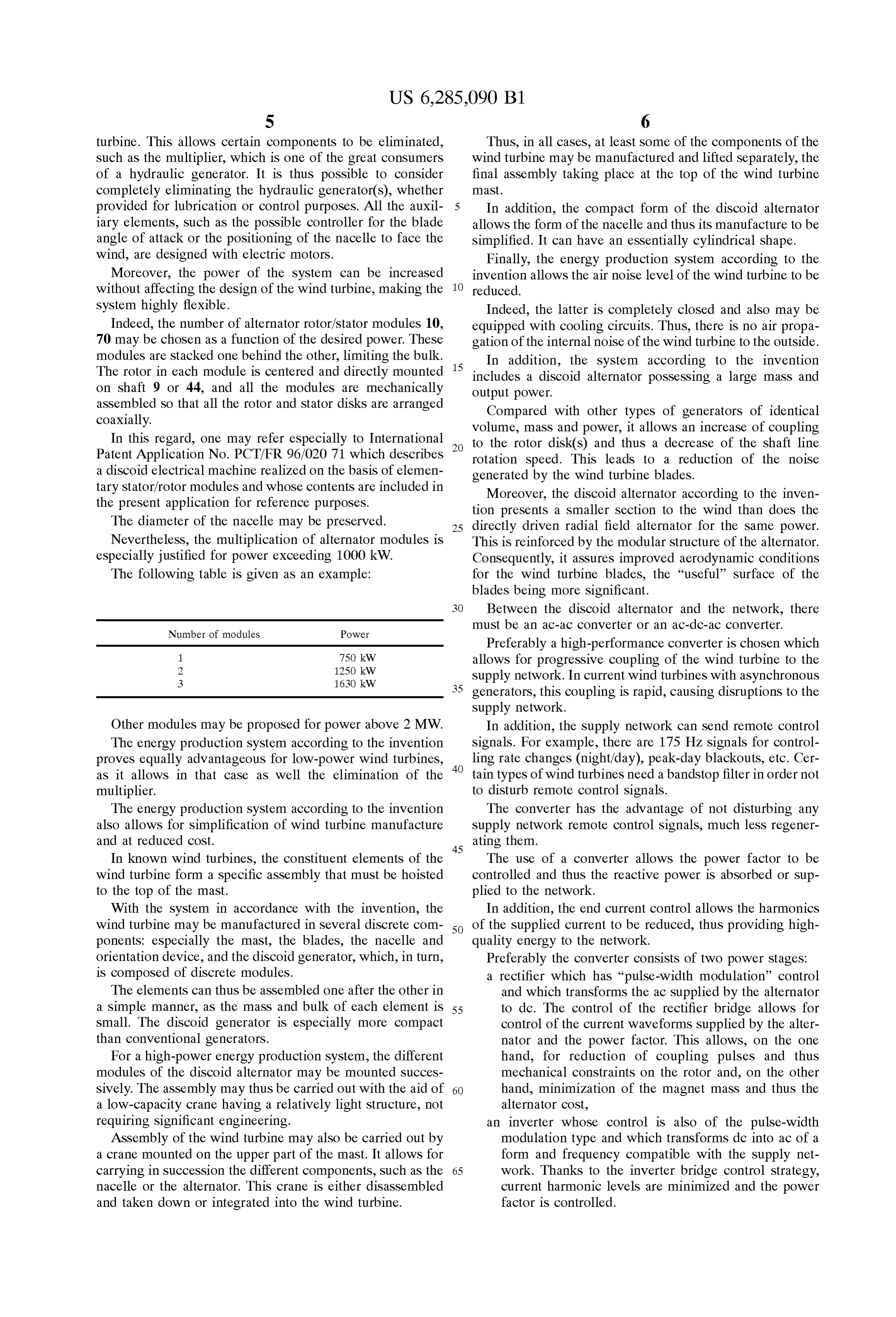
S 6 turbine. This allows certain components to be eliminated, Thus, in all cases, at least Some of the components of the Such as the multiplier, which is one of the great consumers wind turbine may be manufactured and lifted Separately, the of a hydraulic generator. It is thus possible to consider final assembly taking place at the top of the wind turbine completely eliminating the hydraulic generator(s), whether maSt.
provided for lubrication or control purposes. All the auxil In addition, the compact form of the discoid alternator iary elements, Such as the possible controller for the blade allows the form of the nacelle and thus its manufacture to be angle of attack or the positioning of the nacelle to face the Simplified. It can have an essentially cylindrical shape. wind, are designed with electric motors. Finally, the energy production System according to the Moreover, the power of the System can be increased invention allows the air noise level of the wind turbine to be without affecting the design of the wind turbine, making the reduced.
system highly flexible. Indeed, the latter is completely closed and also may be Indeed, the number of alternator rotor/stator modules 10, equipped with cooling circuits. Thus, there is no air propa 70 may be chosen as a function of the desired power. These gation of the internal noise of the wind turbine to the outside. modules are Stacked one behind the other, limiting the bulk. 15 In addition, the System according to the invention The rotor in each module is centered and directly mounted includes a discoid alternator possessing a large mass and on shaft 9 or 44, and all the modules are mechanically output power.
assembled So that all the rotor and Stator disks are arranged Compared with other types of generators of identical coaxially. Volume, mass and power, it allows an increase of coupling In this regard, one may refer especially to International to the rotor disk(s) and thus a decrease of the shaft line Patent Application No. PCT/FR 96/020 71 which describes rotation Speed. This leads to a reduction of the noise a discoid electrical machine realized on the basis of elemen generated by the wind turbine blades. tary Stator/rotor modules and whose contents are included in Moreover, the discoid alternator according to the inven the present application for reference purposes. tion presents a Smaller Section to the wind than does the The diameter of the nacelle may be preserved. 25 directly driven radial field alternator for the same power. Nevertheless, the multiplication of alternator modules is This is reinforced by the modular structure of the alternator. especially justified for power exceeding 1000 kW. Consequently, it assures improved aerodynamic conditions The following table is given as an example: for the wind turbine blades, the “useful” surface of the blades being more significant.
Between the discoid alternator and the network, there must be an ac-ac converter or an ac-dc-ac converter.
Number of modules Power
Preferably a high-performance converter is chosen which
allows for progressive coupling of the wind turbine to the 3 1630 kW Supply network. In current wind turbines with asynchronous 35 generators, this coupling is rapid, causing disruptions to the
Supply network.
Other modules may be proposed for power above 2 MW. In addition, the Supply network can Send remote control The energy production System according to the invention Signals. For example, there are 175 Hz signals for control proves equally advantageous for low-power wind turbines, 40 ling rate changes (night/day), peak-day blackouts, etc. Cer as it allows in that case as well the elimination of the tain types of wind turbines need a bandstop filter in order not multiplier. to disturb remote control Signals. The energy production System according to the invention The converter has the advantage of not disturbing any also allows for Simplification of wind turbine manufacture Supply network remote control Signals, much leSS regener and at reduced cost.
ating them.
In known wind turbines, the constituent elements of the The use of a converter allows the power factor to be wind turbine form a specific assembly that must be hoisted controlled and thus the reactive power is absorbed or Sup to the top of the mast. plied to the network.
With the system in accordance with the invention, the In addition, the end current control allows the harmonics wind turbine may be manufactured in Several discrete com 50 of the Supplied current to be reduced, thus providing high ponents: especially the mast, the blades, the nacelle and quality energy to the network.
orientation device, and the discoid generator, which, in turn, Preferably the converter consists of two power stages: is composed of discrete modules. a rectifier which has “pulse-width modulation” control The elements can thus be assembled one after the other in and which transforms the ac Supplied by the alternator a simple manner, as the mass and bulk of each element is 55 to dc. The control of the rectifier bridge allows for Small. The discoid generator is especially more compact control of the current waveforms supplied by the alter than conventional generators. nator and the power factor. This allows, on the one For a high-power energy production System, the different hand, for reduction of coupling pulses and thus modules of the discoid alternator may be mounted Succes mechanical constraints on the rotor and, on the other sively. The assembly may thus be carried out with the aid of 60 hand, minimization of the magnet mass and thus the a low-capacity crane having a relatively light Structure, not alternator cost, requiring significant engineering. an inverter whose control is also of the pulse-width Assembly of the wind turbine may also be carried out by modulation type and which transforms dc into ac of a a crane mounted on the upper part of the mast. It allows for form and frequency compatible with the Supply net carrying in Succession the different components, Such as the 65 work. Thanks to the inverter bridge control Strategy, nacelle or the alternator. This crane is either disassembled current harmonic levels are minimized and the power and taken down or integrated into the wind turbine. factor is controlled.
Page 11
Use of an alternator with magnets connected to an IGBT output alternator 30 can always operate under the (insulated gate bipolar transistor) converter has the advan conditions required for the electrical Supply network tage of increased protection against Short circuits, especially 32. The storage device 33 may be of any type: if the converter is placed in proximity to the alternator in the hydraulic, gas compression, battery, or any other Sys nacelle. tem.
The use of converters is particularly interesting in isolated The object of the System is to recoup maximum energy networks where the quality of the current generated by the from the wind and to Store it or discharge it according to the wind turbine is of critical importance.
The energy production System according to the invention needs The of the electrical Supply network.
assembly in FIG. 5 has two advantages.
can function at varying Speeds. This allows wind turbine It leads first of all to a smoothing out of the total power functioning to be optimized, especially with weak winds. provided by the wind turbines 20 which is effected naturally The wind turbines may be placed in different environ ments. Optimal wind turbine functioning parameters depend in the dc network.
not only on the wind but also on parameters linked to the In addition, a breakdown of a dc-ac converter 23 does not wind turbine environment, Such as the presence of buildings 15 leadIn to Stopping of the wind turbine. Summary, this assembly allows the use of Standardized or wind orientation.
Preferably the wind turbine includes an overall control modules for the dc-ac converters 23. The base module, for System. Advantageously, this System uses fuZZy logic or example, is a single 1 MVA module. neural network Software. It allows optimization of wind AS previously indicated, the energy Storage System 22 turbine operation by learning and permanent adaptation to may be omitted. In that case, the dc-ac converter outputs are operating parameters, especially at low-speeds. connected in parallel to the network 32, possibly via a transformer.
In this case, the control has a possible effect on blade pitch It is possible to envision as well the different assembly and on the choice of optimal Speed. illustrated in FIG. 6.
When several wind turbines are installed at the same site, their energy production Systems may be interconnected by a 25 In this other assembly, each wind turbine 20 is equipped dc power network. with an ac-dc-ac converter 71 and possibly an elevating transformer 72 at the output. The interconnection of wind
AS previously noted, each wind turbine is provided an turbines ac-ac converter or an ac-dc-ac converter between the discoid is then made at the level of ac network32. It is also alternator and the Supply network. possible to provide a transformer between the parallel FIGS. 5, 6, 7, and 8 refer to and represent different connected outputs of the converters 71 and the network 32. The converter 71 includes one ac-dc converter 23 and one assembly Solutions.
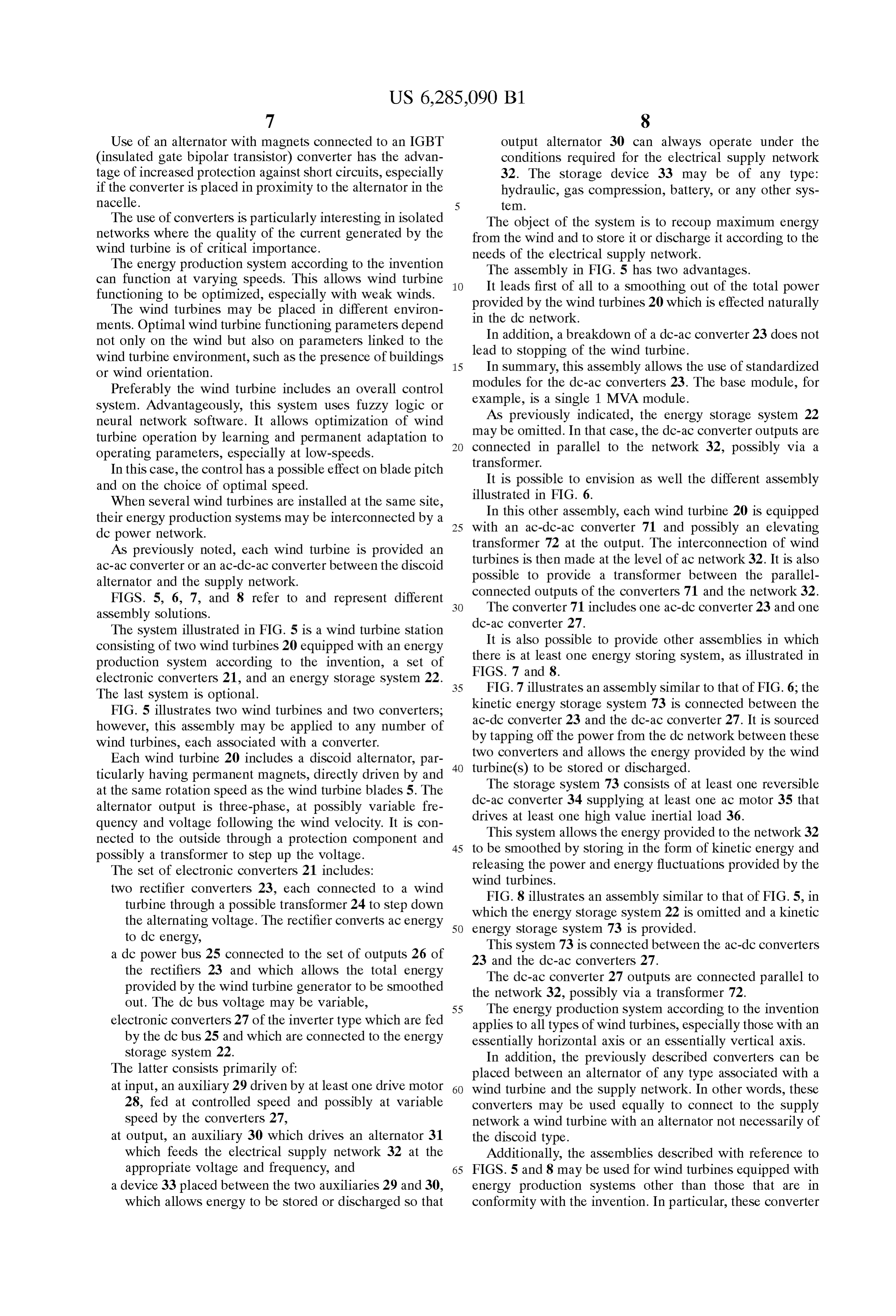
The system illustrated in FIG. 5 is a wind turbine station dc-ac
converter 27.
is also possible to provide other assemblies in which consisting of two wind turbines 20 equipped with an energy production System according to the invention, a set of there is at least one energy Storing System, as illustrated in electronic converters 21, and an energy Storage System 22. 35 FIGS. 7 and 8.
The last System is optional. FIG. 7 illustrates an assembly similar to that of FIG. 6; the FIG. 5 illustrates two wind turbines and two converters; kinetic energy Storage System 73 is connected between the however, this assembly may be applied to any number of ac-dc converter 23 and the dc-ac converter 27. It is sourced wind turbines, each asSociated with a converter. by tapping off the power from the dc network between these two converters and allows the energy provided by the wind
Each wind turbine 20 includes a discoid alternator, par 40 turbine(s) ticularly having permanent magnets, directly driven by and to be stored or discharged. The storage system 73 consists of at least one reversible at the same rotation speed as the wind turbine blades 5. The dc-ac alternator output is three-phase, at possibly variable fre converter 34 Supplying at least one ac motor 35 that quency and Voltage following the wind Velocity. It is con drives at least one high value inertial load 36. nected to the outside through a protection component and 45 This system allows the energy provided to the network 32 possibly a transformer to Step up the Voltage. to be Smoothed by Storing in the form of kinetic energy and The set of electronic converters 21 includes: releasing the power and energy fluctuations provided by the wind turbines.
two rectifier converters 23, each connected to a wind FIG. 8 illustrates an assembly similar to that of FIG. 5, in turbine through a possible transformer 24 to Step down which the alternating Voltage. The rectifier converts ac energy 50 energy the energy Storage System 22 is omitted and a kinetic Storage System 73 is provided.
to dc energy, This system 73 is connected between the ac-dc converters a dc power bus 25 connected to the set of outputs 26 of 23 and the dc-ac converters 27. the rectifiers 23 and which allows the total energy The dc-ac converter 27 outputs are connected parallel to provided by the wind turbine generator to be smoothed the network 32, possibly via a transformer 72. out. The dc bus voltage may be variable, 55 The energy production System according to the invention electronic converters 27 of the inverter type which are fed applies to all types of wind turbines, especially those with an by the dc bus 25 and which are connected to the energy essentially horizontal axis or an essentially vertical axis. Storage System 22. In addition, the previously described converters can be The latter consists primarily of: placed between an alternator of any type associated with a at input, an auxiliary 29 driven by at least one drive motor 60 wind turbine and the Supply network. In other words, these 28, fed at controlled speed and possibly at variable converters may be used equally to connect to the Supply speed by the converters 27, network a wind turbine with an alternator not necessarily of at output, an auxiliary 30 which drives an alternator 31 the discoid type.
which feeds the electrical supply network 32 at the Additionally, the assemblies described with reference to appropriate Voltage and frequency, and 65 FIGS. 5 and 8 may be used for wind turbines equipped with a device 33 placed between the two auxiliaries 29 and 30, energy production Systems other than those that are in which allows energy to be Stored or discharged So that conformity with the invention. In particular, these converter
Page 12
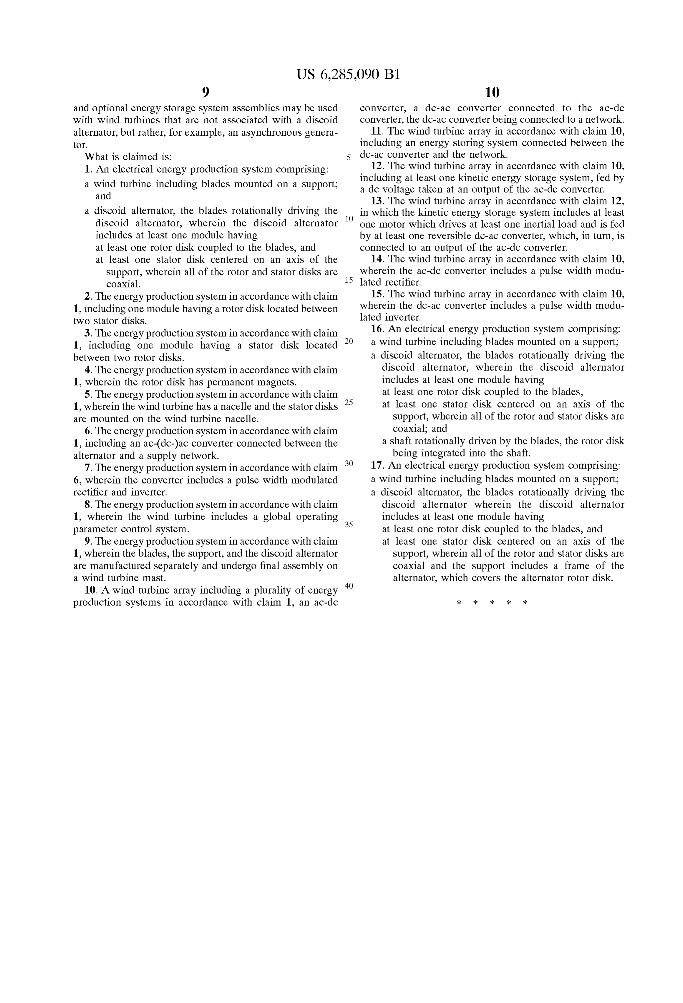
and optional energy Storage System assemblies may be used converter, a dc-ac converter connected to the ac-dc with wind turbines that are not associated with a discoid converter, the dc-ac converter being connected to a network. alternator, but rather, for example, an asynchronous genera 11. The wind turbine array in accordance with claim 10, tor. including an energy Storing System connected between the What is claimed is: dc-ac converter and the network.
1. An electrical energy production System comprising: 12. The wind turbine array in accordance with claim 10, a wind turbine including blades mounted on a Support; including at least one kinetic energy Storage System, fed by and a dc Voltage taken at an output of the ac-dc converter. 13. The wind turbine array in accordance with claim 12, a discoid alternator, the blades rotationally driving the in which the kinetic energy Storage System includes at least discoid alternator, wherein the discoid alternator one motor which drives at least one inertial load and is fed includes at least one module having by at least one reversible dc-ac converter, which, in turn, is at least one rotor disk coupled to the blades, and connected to an output of the ac-dc converter. at least one Stator disk centered on an axis of the 14. The wind turbine array in accordance with claim 10, Support, wherein all of the rotor and Stator disks are 15 wherein the ac-dc converter includes a pulse width modu coaxial. lated rectifier.
2. The energy production System in accordance with claim 15. The wind turbine array in accordance with claim 10, 1, including one module having a rotor disk located between wherein the dc-ac converter includes a pulse width modu two Stator disks. lated inverter.
3. The energy production System in accordance with claim 16. An electrical energy production System comprising: 1, including one module having a Stator disk located a wind turbine including blades mounted on a Support; between two rotor disks. a discoid alternator, the blades rotationally driving the 4. The energy production System in accordance with claim discoid alternator, wherein the discoid alternator 1, wherein the rotor disk has permanent magnets. includes at least one module having 5. The energy production System in accordance with claim 25 at least one rotor disk coupled to the blades, 1, wherein the wind turbine has a nacelle and the Stator disks at least one Stator disk centered on an axis of the are mounted on the wind turbine nacelle. Support, wherein all of the rotor and Stator disks are 6. The energy production System in accordance with claim coaxial; and 1, including an ac-(dc-)ac converter connected between the a shaft rotationally driven by the blades, the rotor disk alternator and a Supply network. being integrated into the Shaft. 7. The energy production System in accordance with claim 17. An electrical energy production System comprising: 6, wherein the converter includes a pulse width modulated a wind turbine including blades mounted on a Support; rectifier and inverter. a discoid alternator, the blades rotationally driving the 8. The energy production System in accordance with claim discoid alternator wherein the discoid alternator 1, wherein the wind turbine includes a global operating 35 includes at least one module having parameter control System. at least one rotor disk coupled to the blades, and 9. The energy production System in accordance with claim at least one Stator disk centered on an axis of the 1, wherein the blades, the Support, and the discoid alternator Support, wherein all of the rotor and Stator disks are are manufactured Separately and undergo final assembly on coaxial and the Support includes a frame of the a wind turbine mast. alternator, which covers the alternator rotor disk. 10. A wind turbine array including a plurality of energy 40 production Systems in accordance with claim 1, an ac-dc
Provenance
- Collection
- Cited prior art
- Original PDF
- patentimages.storage.googleapis.com →
- Filed
- 1998-03-09
- Pages
- 12
- Method
- pdftotext (the PDF's own text layer) + pdftoppm 300dpi page scans
- Source
- Google Patents bibliographic record
- Granted
- 2001-09-04
- Inventors
- Patrick Brutsaert; Jean-Marc Canini; Raymond Michaux; Jeumont Industrie
- Transcribed from
- patentimages.storage.googleapis.com →